US8072476B2 - Printer - Google Patents
Printer Download PDFInfo
- Publication number
- US8072476B2 US8072476B2 US12/890,560 US89056010A US8072476B2 US 8072476 B2 US8072476 B2 US 8072476B2 US 89056010 A US89056010 A US 89056010A US 8072476 B2 US8072476 B2 US 8072476B2
- Authority
- US
- United States
- Prior art keywords
- paper
- unit
- sensor holder
- sensor
- holder
- Prior art date
- Legal status (The legal status is an assumption and is not a legal conclusion. Google has not performed a legal analysis and makes no representation as to the accuracy of the status listed.)
- Active
Links
Images


Classifications
-
- B—PERFORMING OPERATIONS; TRANSPORTING
- B41—PRINTING; LINING MACHINES; TYPEWRITERS; STAMPS
- B41J—TYPEWRITERS; SELECTIVE PRINTING MECHANISMS, i.e. MECHANISMS PRINTING OTHERWISE THAN FROM A FORME; CORRECTION OF TYPOGRAPHICAL ERRORS
- B41J11/00—Devices or arrangements of selective printing mechanisms, e.g. ink-jet printers or thermal printers, for supporting or handling copy material in sheet or web form
- B41J11/0095—Detecting means for copy material, e.g. for detecting or sensing presence of copy material or its leading or trailing end
-
- B—PERFORMING OPERATIONS; TRANSPORTING
- B41—PRINTING; LINING MACHINES; TYPEWRITERS; STAMPS
- B41J—TYPEWRITERS; SELECTIVE PRINTING MECHANISMS, i.e. MECHANISMS PRINTING OTHERWISE THAN FROM A FORME; CORRECTION OF TYPOGRAPHICAL ERRORS
- B41J15/00—Devices or arrangements of selective printing mechanisms, e.g. ink-jet printers or thermal printers, specially adapted for supporting or handling copy material in continuous form, e.g. webs
- B41J15/04—Supporting, feeding, or guiding devices; Mountings for web rolls or spindles
- B41J15/042—Supporting, feeding, or guiding devices; Mountings for web rolls or spindles for loading rolled-up continuous copy material into printers, e.g. for replacing a used-up paper roll; Point-of-sale printers with openable casings allowing access to the rolled-up continuous copy material
-
- B—PERFORMING OPERATIONS; TRANSPORTING
- B41—PRINTING; LINING MACHINES; TYPEWRITERS; STAMPS
- B41J—TYPEWRITERS; SELECTIVE PRINTING MECHANISMS, i.e. MECHANISMS PRINTING OTHERWISE THAN FROM A FORME; CORRECTION OF TYPOGRAPHICAL ERRORS
- B41J3/00—Typewriters or selective printing or marking mechanisms characterised by the purpose for which they are constructed
- B41J3/407—Typewriters or selective printing or marking mechanisms characterised by the purpose for which they are constructed for marking on special material
- B41J3/4075—Tape printers; Label printers
Definitions
- FIG. 3 is a perspective view of the printer, showing a state in which a paper sensor unit opens a paper path;
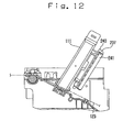
- FIG. 14 is a side view in longitudinal section in a state in which tension is exerted on label paper
- FIG. 20(A) is a side view with an upper sensor frame not mounted, for explaining an operation for mounting an upper sensor frame to a body of the upper sensor holder;
- the tension spring 242 not only pushes out the tension holder 240 toward the projecting portion 232 but also urges it downward about the pivot shaft 238 , i.e., clockwise in the state of FIGS. 13 and 14 .
- the tension holder 240 falls into the recess 233 and causes the label paper 113 to bend.
- the damper mechanism 237 is advantageously attached to the sensor unit 111 .
- the upper sensor holder 111 b of the sensor unit 111 is sure to be brought into its closed regular position. It follows that the damper mechanism 237 is sure to be in operation while the printing operation is performed.
Landscapes
- Accessory Devices And Overall Control Thereof (AREA)
- Handling Of Continuous Sheets Of Paper (AREA)
- Controlling Sheets Or Webs (AREA)
Abstract
A printer includes an upper unit which opens and closes about a fulcrum lying at a rear position of a lower unit, and a paper path which is opened by opening the upper unit. A sensor unit is attached to the lower unit and includes a lower sensor holder and an upper sensor holder which are disposed in opposition to each other via the paper path. The paper path can be opened by pivoting the upper sensor holder relative to the lower sensor holder. When the upper unit is closed, the upper sensor holder is also closed in accordance with a closing pivoting motion of the upper unit.
Description
The present application is a continuation of U.S. patent application Ser. No. 11/475,645, filed Jun. 27, 2006, which claims priority to Japanese Patent Applications P2005-201294 filed on Jul. 11, 2005, P2005-192102 filed on Jun. 30, 2005, and P2005-229388 filed on Aug. 8, 2005.
1. Field of the Invention
The present invention relates to a printer such as a thermal printer for printing a bar code or the like onto label paper.
2. Discussion of the Background
There is known a conventional printer wherein a printer body is divided into a lower unit and an upper unit, and a paper path for the conveyance of paper is formed between the lower unit and the upper unit. In the printer of such a structure, for example, the upper unit moves pivotably relative to the lower unit, centered on a pivot member disposed behind the printer body. Therefore, by attaching a print head and so on to the upper unit and a platen to the lower unit, the paper path can be opened when the upper unit is opened. In the case where a paper holder is provided in the lower unit, a roll of paper can be set easily to the paper holder by opening the paper path.
In the case of a label printer, it is necessary to provide a sensor for detecting a printing start position of label paper. If the sensor is a transmission type sensor, in which a light emitting portion and a light receiving portion are made face to face with each other via the paper path, it is necessary to pass paper between the light emitting portion and the light receiving portion. Therefore, if the label printer has the foregoing vertically divided structure able to open the paper path by opening the upper unit, it is necessary to insert paper into the gap between the light emitting portion and the light receiving portion at the time of setting paper. This paper inserting work is troublesome.
Heretofore, for facilitating the paper setting work, there has been proposed a printer wherein a transmission type sensor is made up of two sensor units capable of being opened and closed. One of a light emitting element and a light receiving element is attached to one sensor unit, while the other is attached to the other sensor unit. Therefore, at the time of setting paper, the paper path is opened by opening one sensor unit with respect to the other sensor unit. The printer having a transmission type sensor of such a structure is described for example in Japanese laid-open Patent Publication No. Hei 11(1999)-199097.
However, in the case of a printer having the aforesaid structure of opening and closing two sensor units, it is necessary that the paper path be opened by pivoting the upper unit and one sensor unit, then after the setting of paper, the paper path be closed by pivoting the upper unit and one sensor unit, and the printer be restored to its usable state. At this time, there is a possibility that the upper unit may be closed while allowing the sensor unit to remain open, causing damage to the sensor unit.
Accordingly, an object of the present invention is to prevent damage of a sensor unit caused by forgetting to close the sensor unit at the time of closing an open upper unit, while adopting a structure able to open a paper path by pivoting one sensor unit.
A printer according to an embodiment of the invention includes a lower unit having a paper holder, an upper unit adapted to open and close pivotably relative to the lower unit, a sensor unit which is attached pivotably to the lower unit by which a paper path is opened and closed, and a damper mechanism attached to the sensor unit and disposed between the sensor unit and the paper holder, the damper mechanism having a paper abutment portion including a roller and a spring, the spring pressing the roller of the paper abutment portion against the paper conveyed along the paper path and apply tension to the paper.
A printer according to another embodiment of the invention includes a lower unit having a paper roll, an upper unit adapted to open and close pivotably relative to the lower unit, a printing section configured to print on paper, which is conveyed from the paper roll along the paper path, at a first portion of a paper path, a sensor unit which: (i) has a lower sensor holder which includes one of a light emitting element and a light receiving element, and an upper sensor holder which includes other one of the light emitting element and the light receiving element, and (ii) is attached to the lower unit so that the paper path passes between the lower sensor holder and the upper sensor holder, a first end of the upper sensor holder being fixed pivotably with respect to the lower unit and a second end of the upper sensor holder being free, and a damper mechanism attached to the sensor unit, the damper mechanism having a paper abutment portion including a roller and a spring, the spring pressing the roller of the paper abutment portion against the paper and applying tension to the paper at a second portion of the paper path between the sensor unit and the paper roll.
A printer according to still another embodiment of the invention includes a lower unit having a paper holder, an upper unit adapted to open and close pivotably relative to the lower unit, a printing section configured to print on paper conveyed from the paper holder along a paper path, a sensor unit which: (i) has a lower sensor holder which includes one of a light emitting element and a light receiving element, and an upper sensor holder which includes other one of the light emitting element and the light receiving element, and (ii) is attached to the lower unit so that the paper path passes between the lower sensor holder and the upper sensor holder, a first end of the upper sensor holder being pivotably attached to the lower sensor holder, the paper path between the upper sensor holder and the lower sensor holder being opened and closed by a second end of the upper sensor holder opposite the first end, and a damper mechanism attached to the sensor unit and disposed between the sensor unit and the paper holder, the damper mechanism having a paper abutment portion including a roller and a spring, the spring pressing the roller toward the paper conveyed along the paper path.
A more complete appreciation of the present invention and many of the attendant advantages thereof will be readily obtained as the same becomes better understood by reference to the following detailed description when considered in connection with the accompanying drawings, wherein:
An embodiment of the present invention will be described in detail hereinafter with reference to the accompanying drawings. This embodiment is an example of application of the present invention to a thermal printer for printing a bar code or the like to label paper.
The printer 101 includes an issuing port 107 for issuing label paper 113 as printing paper to be described later and a power switch 108 at a front side thereof. The issuing port 107 is formed in the shape of a slit between the lower unit 102 and the upper unit 103. The upper unit 103 can be opened and closed relative to the lower unit 102 pivotably about pivot members provided at rear positions. Therefore, upon opening of the upper unit 103, the issuing port 107 is also opened.
In the upper unit 103, an upper base unit 114 and various components, including a printer head 115, are housed within the upper housing 105 whose lower side is open. The print head 115 constitutes a printing section together with the platen roller 110 installed in the lower unit 102. A thermal printing head, for instance, is used for the print head 115.
A paper path 123 is formed between the lower unit 102 and the upper unit 103. The paper path 123 extends from the paper storage 124 to the exterior through the issuing port 107. By opening the upper unit 103, the paper path 123 is opened. The platen roller 110 is disposed in the lower unit 102 and the print head 115 is disposed in the upper unit 103, the paper path 123 is also opened at the printing section by opening the upper unit 103.
On the other hand, even if the upper unit 103 is opened, the sensor unit 111 does not open with respect to the paper path 123. The sensor unit 111 opens the paper path 123 by a manual operation.
The upper unit 103 is provided with a mechanism (not shown) which can keep the upper unit open at a predetermined angle shown in FIG. 2 for instance. Therefore, even if an operator releases his or her hand from the upper unit 103 in the state shown in FIG. 2 , this state is maintained.
The lower sensor holder 111 a is attached to the lower base unit 109 detachably. The upper sensor holder 111 b is attached to the lower sensor holder 111 a so that it can open and close pivotably about a pivot shaft SA1 (see FIGS. 5(A) , 5(B), FIGS. 8(A) to 8(C) , and FIGS. 9(A) , 9(B)) disposed on one side of the paper path 123 in the paper width direction. As shown in FIG. 8(A) , when the upper sensor holder 111 b opens pivotably at a predetermined angle (about 120°), it comes into abutment against a part of the lower base unit 109 and is retained in this position. This part of the lower base unit 109 is a corner of a stepped portion 109 a formed in the lower base unit 109 while being positioned on the left side when seen from the front side of the printer 101. A support portion 118 is fixed to the upper sensor holder 111 b at the position where the upper sensor holder 111 b abuts against the corner of the stepped portion 109 a of the lower base unit 109 (see FIG. 2 and FIGS. 8(A) to 8(C) ). Such an abutting mechanism between a part of the lower base unit 109 and the support portion 118 of the upper sensor holder 111 b constitutes a support mechanism which positions the pivotably opened upper sensor holder 111 b at a predetermined angle.
Since the pivotal angle of the upper sensor holder 111 b thus opened is about 120° relative to the lower sensor holder 111 a, the free end of the upper sensor holder 111 b protrudes to the outside of the lower housing 104. This state of the upper sensor holder 111 b is designated an “open condition.”
The upper sensor holder 111 b is provided at its free end with a grip portion 119, which is grasped when pivotably opening or closing the upper sensor holder 111 b. As shown in FIG. 2 , the upper base unit 114 is provided with a pressing member 120 formed by a leaf spring in the vicinity of the printer head 115 and on the right side as seen from the front side of the printer 101. The pressing member 120 is positioned so as to push down the grip portion 119 with an elastic force when the upper unit 103 is closed.
The upper sensor holder 111 b is also provided at its free end with a locking mechanism 121, which is described in detail below (see FIG. 9 ).
The lower sensor holder 111 a and the upper sensor holder 111 b are formed as resin-molded products. The support portion 118 and the grip portion 119 of the upper sensor holder 111 b are also formed of resin.
A displacing mechanism is provided in the lower base unit 109 and the upper base unit 114. A main element of the displacing mechanism is a slider 122. More specifically, a long hole 116 is formed horizontally in the lower base unit 109 in a left side position as seen from the front side of the printer 101. The slider 122 is positioned inside the lower base unit 109 and is placed on the stepped portion 109 a of the lower base unit 109. In this state, the lower base unit 109 is connected slidably to the long hole 116. A connecting portion 117 is pivotably connected at one end thereof to one support frame 114 a and is pivotably connected at the other end to the connection of the slider 122 relative to the long hole 116.
When the upper sensor holder 111 b is in the “open condition”, the upper sensor holder 111 b keeping the paper path 123 open is pushed by the slider 122 and pivots in the direction to close the paper path 123, in accordance with movement of the upper unit 103 from its open condition shown in FIG. 5(A) to its closed condition shown in FIG. 5(B) . As to the structure which brings about such an operation of the displacing mechanism, a description will be given later with reference to FIGS. 7(A) to 7(C) and FIGS. 8(A) to 8(C) .
As shown in FIG. 8(C) , as the slider 122 moves still more forward, the width of the slider 122 at the position P expands to the width W3, so that the slider 122 further pushes the upper sensor holder 111 b, whereby the sensor holder 111 b is pushed until the angle between it and the lower sensor holder 111 a becomes an acute angle. Consequently, the upper sensor holder 111 b drops rotationally by its own weight about the pivot shaft SA1 so as to approach the lower sensor holder 111 a.
A buffer member for avoiding damage caused by collision may be provided on the upper sensor holder 111 b at the position where the upper sensor holder comes into contact with the slider 122. The buffer member may be a leaf spring having resilience.
The material and shape of the slider 122 shown in this embodiment are only an example and no limitation is made thereto insofar as it is possible to create an external force for displacing the upper sensor holder 111 b which is in the “open condition,” as shown in FIG. 8 .
As shown in FIG. 9(B) , a spacer 125 projects from the underside on the free end side of the upper sensor holder 111 b. With the upper sensor holder 111 b closed and locked by the locking mechanism 121, the spacer 125 comes into abutment against the lower sensor holder 111 a, whereby an appropriate space is formed for the paper path 123 between the lower sensor holder 111 a and the upper sensor holder 111 b.
The engaging motion of the projection 121 a with the retaining portion 121 b in the locking mechanism 121 will now be described in more detail. As shown in FIG. 8(C) , even if the upper sensor holder 111 b is dropped rotationally by applying an external force thereto, the projection 121 a is not brought into engagement with the retaining portion 121 b, but the upper sensor holder 111 b assumes a pre-lock state in which it is slightly with respect to the lower sensor holder 111 a as in FIG. 9(A) . The pre-lock state is defined as a state in which the retaining portion 121 b supports the projection 121 a and the upper sensor holder 111 b keeps the paper path 123 slightly opened. When the upper sensor holder 111 b is in its pre-lock state, the upper sensor holder 111 b can be brought into its locked state easily by pushing the upper sensor holder in the vicinity of the free end thereof from above.
The upper base unit 114 is provided with the pressing member 120 described above. The pressing member 120 is positioned so that, when the upper unit 103 is closed, the pressing member 120 comes into contact with the grip portion 119 of the upper sensor holder 111 b, which is in the state shown in FIG. 9(A) . When the upper unit 103 is closed, the pressing member 120 pushes down the grip portion 119. In this case, the urging force is set to a sufficient force for locking the upper sensor holder 111 b. Thus, even if the operator forget to depress the upper sensor holder 111 b into the locked state, by merely closing the upper unit 103, the pressing member 120 depresses the grip portion 119 and the upper sensor holder 111 b can be locked. Besides, by using the pressing member 120 as a resilient member at the position of contact with the grip portion 119, it is possible to avoid damage of the grip portion 119 caused by the contact.
According to this embodiment, as set forth above, when the upper unit 103 is opened for replacement of the label paper 113 and the upper sensor holder 111 b of the sensor unit 111 is opened to open the paper path 123, the opened upper sensor holder 111 b performs its closing pivotal motion by merely closing the upper unit 103 after the end of a paper setting work. Therefore, it is possible to prevent the upper sensor holder 111 b from being pinched and damaged between the lower unit 102 and the upper unit 103. In this case, by merely closing the upper unit 103, the locking mechanism 121 in the upper sensor holder 111 b is also locked, so that it is possible to avoid forgetting to lock the sensor unit 111. Consequently, after setting the label paper 113 to the paper path 123, the printer 101 can be immediately brought into an employable state by merely closing the upper unit 103.
The printer 101 of this embodiment further includes a damper mechanism. A description will be given below about the damper mechanism with reference to FIGS. 10 and 11 .
A description will now be given about the operation of the damper mechanism 237. For setting the label paper 113, first the upper unit 103 is opened to open the upper surface of the lower unit 102. Then, the upper sensor holder 111 b of the sensor unit 111 is opened to open the portion which overlies the paper path 123. In this state, the rolled label paper 113 is set to the paper storage 124 from above. At this time, either the inwards- or the outwards-wound mode can be selected. The unwinding direction of the label paper 113 differs depending on whether the paper set mode is the inwards- or the outwards-wound mode and therefore care must be exercised at the time of setting the label paper 113. In the inwards-wound mode, the paper is drawn out in the direction shown in FIG. 10 , while in the outwards-wound mode, the paper is drawn out in the direction shown in FIG. 11 . In the inwards-wound mode, if the label paper 113 is used and has a large roll diameter, the label paper comes into contact with the projecting portion 232, while in the outwards-wound mode, the label paper does not contact the projecting portion 232. In any event, the label paper 113 is drawn out until the tip thereof reaches a position outside the issuing port 107 and is set to the paper path 123. In this state, the upper sensor holder 111 b of the sensor unit 111 is brought down and set to its regular position, and then the upper unit 103 is closed.
With the upper unit 103 closed and with the label paper 113 in the inwards-wound mode, the tension roller 241 in the damper mechanism 237 pushes the label paper 113 with the force of the tension spring 242, causing the paper to fall into the recess 233 and thereby allowing the paper to assume a bent state. In the outwards-wound mode, the label paper 113 is in a wound-up state around the tension roller 241 and is largely bent at this portion, and the tension roller 241 is moved upstream with the tension spring 242. When the upper unit 103 is closed into a printable state, the sensor unit 111 is also set to its regular position. The damper mechanism 237 is also integral with the sensor unit 111, so in the printable state the damper mechanism 237 is sure to operate.
After the label paper 113 is set, a printing operation is started. During printing, the motion of the label paper 113 is intermittent. That is, since the feed of paper is not performed in a continuous manner, the rolled portion of the label paper 113 also repeats rotations and stops in an intermittent manner. For example, when the feed of paper for printing stops, the rolled portion of the label paper 113 stops after rotating to a certain degree by the force of inertia, so that the label paper 113 present in the paper path 123 is in a state having slackness. Therefore, when the label paper 113 is fed for the next printing, for the feed quantity corresponding to that slackness, the paper is fed at an exact feed rate because of low resistance to the feeding, but when the slackness is exhausted it is required to rotate the rolled portion of the label paper 113, with a consequent increase in resistance to the feeding. In this case, tension is developed in the label paper 113 and the tension roller 241 in the damper mechanism 237 moves against the force of the tension spring 242 and performs a buffering action to prevent an abrupt generation of tension. Then, tension increases slowly and causes the rolled portion of the label paper 113 to rotate, so that the feed rate of the label paper in the printing section does not change. That is, the damper mechanism 237 attached to the sensor unit 111 not only causes bending of a part of the label paper 113 set to the paper path 123 but also diminishes the degree of bending of the label paper 113 in accordance with the tension applied to the same paper. The buffering action thus exhibited will be described below in each of the inwards- and outwards-wound modes.
In the inwards-wound mode, the paper portion corresponding to the bent length in the recess 233 contributes to the buffering action. That is, the tension roller 241 moves upward against the force of the tension spring 242, causing a buffering action to be exhibited to a degree corresponding to the bent length. At this time, if the diameter and weight of the rolled portion of the label paper 113 are large, the bent length in the recess 233 is ensured because the paper is sure to contact the projecting portion 232, thus ensuring a satisfactory buffering action. As the diameter of the rolled portion of the label paper 113 becomes smaller, the label paper 113 is no longer in contact with the projecting portion 232, but in this case the weight of the paper rolled portion becomes smaller and so there occurs no problem even if the buffering action during the feeding of the paper is weak.
In the outwards-wound mode, even with an increase of tension acting on the label paper 113, there occurs a buffering action because the tension roller 241 moves forward against the tension of the tension spring 242, thus preventing the occurrence of any large change in tension. In the case where the printing operation continues for a long time, the tension roller 241, in both inwards- and outwards-wound modes, reverts to its original position with the force of the tension spring 242 during the printing operation.
Thus, with the damper mechanism 237, the feed rate of the label paper 113 can be kept constant and a highly accurate printing operation can be effected even when the line width and line spacing are strict as is the case with bar code printing.
It should be noted that the damper mechanism 237 is advantageously attached to the sensor unit 111. In this embodiment, when the upper unit 103 is closed, the upper sensor holder 111 b of the sensor unit 111 is sure to be brought into its closed regular position. It follows that the damper mechanism 237 is sure to be in operation while the printing operation is performed.
Moreover, as described previously, the label paper 113 is wound in a rolled state and the damper mechanism 237 contacts the label paper 113 at the same position in both the case where the label paper 113 is set along the inwards-wound path and the case where it is set along the outward-wound path. Thus, it is easy to make the selection between the inwards- and outwards-wound paper feed modes.
Further, since the projecting portion 232 is formed in the paper path 123 to keep the label paper 113 bent by the damper mechanism 237 even when the winding diameter of the label paper held in a paper storage 124 is large, there does not occur a difference in the buffering action depending on the size of the rolled portion of the label paper.
In the printer 101 of this embodiment, the sensor unit 111 is unitized and is attached to the lower base unit 109 detachably. Now, with reference to FIGS. 15 to 20 , the following description is provided about the structure for mounting and dismounting the sensor unit 111.
Mounting and dismounting of the sensor unit 111 relative to the lower base unit 109 are performed by a structure wherein two pairs of retaining pawls 301 and 302 provided in the sensor unit 111 are engaged with two pairs of retaining portions 303 and 304 provided in the lower base unit 109. More specifically, the sensor unit 111 has a pair of retaining pawls 301 provided at front positions and a pair of retaining pawls 302 provided at rear corner positions, while the lower base unit 109 has a pair of retaining portions 303 and a pair of retaining portions 304 engageable respectively with the retaining pawls 301 and 302. Since the retaining pawls 301 and 302 are engaged with the retaining portions 303 and 304 disengageably, the sensor unit 111 is attached to the lower base unit 109 detachably and is disposed at a fixed position.
One pair of retaining pawls 302 provided in the sensor unit 111 have U-bent projecting portions 305. The U-bent portions 305 are formed by molding integrally with the lower sensor holder 111 a, which is formed as a resin-molded product, and therefore have elasticity.
The light emitting element LEE of the transmission type sensor TTS and the reflection type sensor RTS, in a mounted state on a wiring substrate, are attached to the lower sensor frame 308. The light receiving element LRE of the transmission type sensor TTS, in a mounted state on a wiring substrate, is attached to the upper sensor frame 309. The wiring substrate is slidable in the longitudinal direction of the lower and upper sensor frames 308, 309.
To remove the sensor unit 111 from the lower base unit 109, the U-bent portions 305 are deflected to disengage the retaining pawls 302 from the retaining portions 304 and then the rear portion of the sensor unit 111 is lifted upward, whereby the rear portion of the sensor unit 111 becomes free with the engaged portions of the retaining pawls 301 with the retaining portions 303 as a fulcrum, as shown in FIG. 18(A) . Thus, by disengaging the retaining pawls 301 from the retaining portions 303 it is possible to remove the sensor unit 111 from the lower base unit 109.
Therefore, the mounting and dismounting of the sensor unit 111 relative to the printer 101 can be done easily without using such fixing members as screws or such a tool as a screwdriver.
To remove the lower sensor frame 308 from the lower sensor holder 111 a, the lower retaining pawls 311 are pushed and bent from holes of the lower retaining portions 312 so as to disengage the lower retaining pawls 311 from the lower retaining portions 312. Upon bending and disengagement of the lower retaining pawls 311, the lower retaining pawls 311 are pushed up from the holes of the lower retaining portions 312, causing the lower sensor frame 308 to rise. As a result, the lower retaining pawls 311 are pushed into a bent state by the lower sensor holder 111 a, as shown in FIG. 19(A) . Therefore, by lifting the lower sensor frame 308, the lower sensor frame 308 can be removed from the lower sensor holder 111 a.
To remove the upper sensor frame 309 from the state shown in FIG. 20(B) , the upper retaining pawls 314 are disengaged into the state shown in FIG. 20(A) , and then the upper sensor frame 309 is removed from the recess 313 of the upper sensor holder 111 b, whereby the upper sensor frame 309 can be removed from the upper sensor holder 111 b.
According to this embodiment, since the sensor unit 111 can be mounted to and removed from the printer 101 without using such a tool as a screwdriver, even in the event of failure of the sensor unit 111, the sensor unit 111 can be replaced in a simple manner. The lower sensor frame 308 and the upper sensor frame 309 can also be mounted to and removed from the sensor unit 111 and therefore it is possible to effect replacement of only a specific sensor portion, whereby the workability of the sensor unit 111 and printer 101 can be further improved.
Although in this embodiment the light emitting element LEE and the light receiving element LRE in the transmission type sensor TTS are attached to the lower sensor frame 308 and the upper sensor frame 309, respectively, the light receiving element LRE may be attached to the lower sensor frame 308 and the light emitting element LEE may be attached to the upper sensor frame 309. Further, the reflection type sensor RTS may be attached to the upper sensor frame 309.
Obviously, numerous modifications and variations of the present invention are possible in light of the above teachings. It is therefore to be understood that within the scope of the appended claims, the invention may be practiced otherwise than as specifically described herein.
Claims (20)
1. A printer, comprising;
a lower unit including a paper holder;
an upper unit adapted to open and close pivotably relative to the lower unit;
a sensor unit which is attached pivotably to the lower unit by which a paper path is opened and closed; and
a damper mechanism attached to the sensor unit and disposed between the sensor unit and the paper holder, the damper mechanism having a paper abutment portion including a roller and a spring, the spring pressing the roller of the paper abutment portion against paper conveyed along the paper path and applying tension to the paper.
2. The printer according to claim 1 , wherein the roller extends on a plane of the paper path and in a direction orthogonal to an advancing direction of the paper.
3. The printer according to claim 2 , wherein the roller is rotated when the paper is conveyed along the paper path.
4. The printer according to claim 1 , wherein the spring has a fixed portion and a movable portion that rotates the paper abutment portion about the fixed portion.
5. The printer according to claim 1 , wherein the roller is pressed against the paper conveyed along the paper path in a direction substantially perpendicular to a plane of the paper path.
6. A printer, comprising:
a lower unit including a paper roll;
an upper unit adapted to open and close pivotably relative to the lower unit;
a printing section configured to print on paper, which is conveyed from the paper roll along a paper path, at a first portion of the paper path;
a sensor unit which: (i) comprises a lower sensor holder which includes one of a light emitting element and a light receiving element, and an upper sensor holder which includes other one of the light emitting element and the light receiving element, and (ii) is attached to the lower unit so that the paper path passes between the lower sensor holder and the upper sensor holder, a first end of the upper sensor holder being fixed pivotably with respect to the lower unit and a second end of the upper sensor holder being free; and
a damper mechanism attached to the sensor unit, the damper mechanism having a paper abutment portion including a roller and a spring, the spring pressing the roller of the paper abutment portion against the paper and applying tension to the paper at a second portion of the paper path between the sensor unit and the paper roll.
7. The printer according to claim 6 , wherein the roller extends on a plane of the paper path and in a direction orthogonal to an advancing direction of the paper.
8. The printer according to claim 7 , wherein the roller is rotated when the paper at the second portion of the paper path is conveyed along the paper path.
9. The printer according to claim 6 , wherein the spring has a fixed portion and a movable portion that rotates the paper abutment portion about the fixed portion.
10. The printer according to claim 6 , wherein the paper abutment portion is disposed between the paper path and the upper unit.
11. The printer according to claim 10 , wherein the paper abutment portion is disposed at different positions between the paper path and the upper unit depending on a diameter of the paper roll.
12. The printer according to claim 10 , wherein the paper abutment portion is disposed at different positions between the paper path and the upper unit depending on whether the paper roll is inwards-wound or outwards-wound.
13. The printer according to claim 6 , wherein a degree of bending of the paper in the second portion of the paper path varies in accordance with a diameter of the paper roll.
14. The printer according to claim 6 , wherein a degree of bending of the paper at the second portion of the paper path varies in accordance with whether the paper roll is inwards-wound or outwards-wound.
15. A printer, comprising:
a lower unit including a paper holder;
an upper unit adapted to open and close pivotably relative to the lower unit;
a printing section configured to print on paper conveyed from the paper holder along a paper path;
a sensor unit which: (i) comprises a lower sensor holder which includes one of a light emitting element and a light receiving element, and an upper sensor holder which includes other one of the light emitting element and the light receiving element, and (ii) is attached to the lower unit so that the paper path passes between the lower sensor holder and the upper sensor holder, a first end of the upper sensor holder being pivotably attached to the lower sensor holder, the paper path between the upper sensor holder and the lower sensor holder being opened and closed by a second end of the upper sensor holder opposite the first end; and
a damper mechanism attached to the sensor unit and disposed between the sensor unit and the paper holder, the damper mechanism having a paper abutment portion including a roller and a spring, the spring pressing the roller toward the paper conveyed along the paper path.
16. The printer according to claim 15 , wherein the paper abutment portion is disposed between the paper path and the upper unit.
17. The printer according to claim 15 , wherein the roller extends on a plane of the paper path and in a direction orthogonal to an advancing direction of the paper.
18. The printer according to claim 17 , wherein a width of the roller is at least as wide as a width of the paper conveyed along the paper path.
19. The printer according to claim 18 , wherein the roller is rotated when the paper is conveyed along the paper path.
20. The printer according to claim 15 , wherein the spring has a fixed portion and a movable portion that rotates the paper abutment portion about the fixed portion.
Priority Applications (1)
| Application Number | Priority Date | Filing Date | Title |
|---|---|---|---|
| US12/890,560 US8072476B2 (en) | 2005-06-30 | 2010-09-24 | Printer |
Applications Claiming Priority (8)
| Application Number | Priority Date | Filing Date | Title |
|---|---|---|---|
| JP2005-192102 | 2005-06-30 | ||
| JP2005192102A JP4615382B2 (en) | 2005-06-30 | 2005-06-30 | Printer |
| JP2005201294A JP4566847B2 (en) | 2005-07-11 | 2005-07-11 | Printer |
| JP2005-201294 | 2005-07-11 | ||
| JP2005-229388 | 2005-08-08 | ||
| JP2005229388A JP4469314B2 (en) | 2005-08-08 | 2005-08-08 | Printer |
| US11/475,645 US7872662B2 (en) | 2005-06-30 | 2006-06-27 | Printer |
| US12/890,560 US8072476B2 (en) | 2005-06-30 | 2010-09-24 | Printer |
Related Parent Applications (1)
| Application Number | Title | Priority Date | Filing Date |
|---|---|---|---|
| US11/475,645 Continuation US7872662B2 (en) | 2005-06-30 | 2006-06-27 | Printer |
Publications (2)
| Publication Number | Publication Date |
|---|---|
| US20110072989A1 US20110072989A1 (en) | 2011-03-31 |
| US8072476B2 true US8072476B2 (en) | 2011-12-06 |
Family
ID=37007456
Family Applications (4)
| Application Number | Title | Priority Date | Filing Date |
|---|---|---|---|
| US11/475,645 Active 2029-06-30 US7872662B2 (en) | 2005-06-30 | 2006-06-27 | Printer |
| US12/890,560 Active US8072476B2 (en) | 2005-06-30 | 2010-09-24 | Printer |
| US12/890,555 Active US8068127B2 (en) | 2005-06-30 | 2010-09-24 | Printer |
| US13/280,242 Active US8350881B2 (en) | 2005-06-30 | 2011-10-24 | Printer |
Family Applications Before (1)
| Application Number | Title | Priority Date | Filing Date |
|---|---|---|---|
| US11/475,645 Active 2029-06-30 US7872662B2 (en) | 2005-06-30 | 2006-06-27 | Printer |
Family Applications After (2)
| Application Number | Title | Priority Date | Filing Date |
|---|---|---|---|
| US12/890,555 Active US8068127B2 (en) | 2005-06-30 | 2010-09-24 | Printer |
| US13/280,242 Active US8350881B2 (en) | 2005-06-30 | 2011-10-24 | Printer |
Country Status (3)
| Country | Link |
|---|---|
| US (4) | US7872662B2 (en) |
| EP (1) | EP1738914B1 (en) |
| DE (1) | DE602006012137D1 (en) |
Cited By (1)
| Publication number | Priority date | Publication date | Assignee | Title |
|---|---|---|---|---|
| US9233566B2 (en) | 2010-03-31 | 2016-01-12 | Fujitsu Component Limited | Printer |
Families Citing this family (26)
| Publication number | Priority date | Publication date | Assignee | Title |
|---|---|---|---|---|
| EP1738914B1 (en) * | 2005-06-30 | 2010-02-10 | Toshiba Tec Kabushiki Kaisha | Printer |
| US8089666B2 (en) * | 2007-01-25 | 2012-01-03 | Ricoh Company, Ltd. | Image forming apparatus |
| US8154770B2 (en) * | 2007-01-31 | 2012-04-10 | Ricoh Company, Ltd. | Image forming apparatus |
| US8194255B2 (en) * | 2007-09-14 | 2012-06-05 | Ricoh Company, Ltd. | Image forming apparatus |
| GB2459531B (en) * | 2008-04-29 | 2010-10-13 | Dymo Nv | Label printer |
| JP5576138B2 (en) * | 2010-02-10 | 2014-08-20 | シチズンホールディングス株式会社 | Thermal printer |
| WO2011130319A1 (en) * | 2010-04-12 | 2011-10-20 | Zih Corp. | Mobile printer networking and interfacing |
| JP2013039779A (en) * | 2011-08-18 | 2013-02-28 | Fujitsu Component Ltd | Printer apparatus and printer head |
| CA2852928A1 (en) * | 2011-10-20 | 2013-04-25 | Source Technologies, Llc | Top of form sensor |
| CN103660599A (en) * | 2012-09-21 | 2014-03-26 | 致伸科技股份有限公司 | Printing apparatus |
| JP6116377B2 (en) * | 2013-05-28 | 2017-04-19 | サトーホールディングス株式会社 | Printer |
| JP6435848B2 (en) * | 2014-12-22 | 2018-12-12 | セイコーエプソン株式会社 | Printing device |
| JP1548340S (en) * | 2015-09-07 | 2016-04-25 | ||
| JP6829008B2 (en) | 2016-05-24 | 2021-02-10 | 富士通コンポーネント株式会社 | Printer |
| EP3513978B1 (en) | 2016-09-13 | 2022-06-08 | Sato Holdings Kabushiki Kaisha | Printer |
| JP6845862B2 (en) * | 2016-09-13 | 2021-03-24 | サトーホールディングス株式会社 | Printer |
| CN109689374B (en) * | 2016-09-13 | 2020-11-03 | 佐藤控股株式会社 | printer |
| EP3513977B1 (en) | 2016-09-13 | 2021-03-10 | Sato Holdings Kabushiki Kaisha | Printer |
| WO2019167321A1 (en) | 2018-02-28 | 2019-09-06 | サトーホールディングス株式会社 | Printer |
| USD936139S1 (en) | 2018-02-28 | 2021-11-16 | Sato Holdings Kabushiki Kaisha | Thermal head for a printer |
| US10882328B2 (en) | 2018-02-28 | 2021-01-05 | Sato Holdings Kabushiki Kaisha | Thermal head for printer |
| USD910746S1 (en) | 2018-08-09 | 2021-02-16 | Sato Holdings Kabushiki Kaisha | Thermal head for a printer |
| US11123999B2 (en) | 2018-09-03 | 2021-09-21 | Sanford, L.P. | Cassettes and label printers therefor |
| JP7271922B2 (en) * | 2018-11-30 | 2023-05-12 | ブラザー工業株式会社 | printer |
| WO2020209834A1 (en) | 2019-04-08 | 2020-10-15 | Hewlett-Packard Development Company, L.P. | Devices for retaining articles |
| JP7660025B2 (en) * | 2021-05-21 | 2025-04-10 | セイコーインスツル株式会社 | Printer and method for manufacturing the same |
Citations (13)
| Publication number | Priority date | Publication date | Assignee | Title |
|---|---|---|---|---|
| JPH08258827A (en) | 1995-03-27 | 1996-10-08 | Tec Corp | Label printer |
| JPH11199098A (en) | 1998-01-07 | 1999-07-27 | Toshiba Tec Corp | Printer |
| JPH11199097A (en) | 1998-01-07 | 1999-07-27 | Toshiba Tec Corp | Printer |
| JP2000016651A (en) | 1998-06-30 | 2000-01-18 | Toshiba Tec Corp | Receipt printer |
| JP2000071533A (en) | 1998-08-28 | 2000-03-07 | Toshiba Tec Corp | Label printer |
| JP2000229405A (en) | 1999-02-10 | 2000-08-22 | Canon Inc | Recording device |
| US20010005216A1 (en) * | 1999-05-13 | 2001-06-28 | Akira Takahashi | Thermal printer |
| US20010026725A1 (en) | 1996-11-27 | 2001-10-04 | Steven Petteruti | Thermal printer |
| JP2001277468A (en) | 2000-03-30 | 2001-10-09 | Riso Kagaku Corp | Image forming device |
| JP2003146493A (en) | 2001-11-05 | 2003-05-21 | Citizen Watch Co Ltd | Roll paper hold device and printer |
| US20030103133A1 (en) | 2001-11-05 | 2003-06-05 | Masahiko Ueda | Thermal transfer printer |
| US7852360B2 (en) * | 2007-10-04 | 2010-12-14 | Seiko Instruments Inc. | Thermal printer unit and printing device |
| US7872662B2 (en) * | 2005-06-30 | 2011-01-18 | Toshiba Tec Kabushiki Kaisha | Printer |
Family Cites Families (2)
| Publication number | Priority date | Publication date | Assignee | Title |
|---|---|---|---|---|
| JP2006317863A (en) * | 2005-05-16 | 2006-11-24 | Matsushita Electric Ind Co Ltd | Image forming apparatus |
| JP5298954B2 (en) * | 2008-04-10 | 2013-09-25 | セイコーエプソン株式会社 | Printer recording paper transport control method and printer |
-
2006
- 2006-06-22 EP EP06012854A patent/EP1738914B1/en not_active Not-in-force
- 2006-06-22 DE DE602006012137T patent/DE602006012137D1/en active Active
- 2006-06-27 US US11/475,645 patent/US7872662B2/en active Active
-
2010
- 2010-09-24 US US12/890,560 patent/US8072476B2/en active Active
- 2010-09-24 US US12/890,555 patent/US8068127B2/en active Active
-
2011
- 2011-10-24 US US13/280,242 patent/US8350881B2/en active Active
Patent Citations (14)
| Publication number | Priority date | Publication date | Assignee | Title |
|---|---|---|---|---|
| JPH08258827A (en) | 1995-03-27 | 1996-10-08 | Tec Corp | Label printer |
| US20010026725A1 (en) | 1996-11-27 | 2001-10-04 | Steven Petteruti | Thermal printer |
| JPH11199098A (en) | 1998-01-07 | 1999-07-27 | Toshiba Tec Corp | Printer |
| JPH11199097A (en) | 1998-01-07 | 1999-07-27 | Toshiba Tec Corp | Printer |
| JP2000016651A (en) | 1998-06-30 | 2000-01-18 | Toshiba Tec Corp | Receipt printer |
| JP2000071533A (en) | 1998-08-28 | 2000-03-07 | Toshiba Tec Corp | Label printer |
| JP2000229405A (en) | 1999-02-10 | 2000-08-22 | Canon Inc | Recording device |
| US20010005216A1 (en) * | 1999-05-13 | 2001-06-28 | Akira Takahashi | Thermal printer |
| US6501498B2 (en) | 1999-05-13 | 2002-12-31 | Heiwa Tokei Manufacturing Co., Ltd. | Thermal printer |
| JP2001277468A (en) | 2000-03-30 | 2001-10-09 | Riso Kagaku Corp | Image forming device |
| JP2003146493A (en) | 2001-11-05 | 2003-05-21 | Citizen Watch Co Ltd | Roll paper hold device and printer |
| US20030103133A1 (en) | 2001-11-05 | 2003-06-05 | Masahiko Ueda | Thermal transfer printer |
| US7872662B2 (en) * | 2005-06-30 | 2011-01-18 | Toshiba Tec Kabushiki Kaisha | Printer |
| US7852360B2 (en) * | 2007-10-04 | 2010-12-14 | Seiko Instruments Inc. | Thermal printer unit and printing device |
Non-Patent Citations (5)
| Title |
|---|
| Chinese Office Action dated Apr. 24, 2009 (3 pages), and partial English translation thereof (1 page), issued in counterpart Chinese Application Serial No. 200610106196.8. |
| Extended European Search Report dated Mar. 19, 2008, issued in a counterpart European Application. |
| Japanese Office Action dated Jul. 28, 2009 and English Translation thereof issued in a counterparts Japanese Application No. 2005-229388. |
| Japanese Office Action dated Jun. 1, 2010, Japanese Patent Application No. 2005-192102. |
| Japanese Office Action dated May 11, 2010 and English translation thereof issued in counterpart Japanese Application No. 2005-201294. |
Cited By (2)
| Publication number | Priority date | Publication date | Assignee | Title |
|---|---|---|---|---|
| US9233566B2 (en) | 2010-03-31 | 2016-01-12 | Fujitsu Component Limited | Printer |
| US9233567B2 (en) | 2010-03-31 | 2016-01-12 | Fujitsu Component Limited | Printer |
Also Published As
| Publication number | Publication date |
|---|---|
| US8350881B2 (en) | 2013-01-08 |
| US7872662B2 (en) | 2011-01-18 |
| EP1738914B1 (en) | 2010-02-10 |
| US8068127B2 (en) | 2011-11-29 |
| US20110074858A1 (en) | 2011-03-31 |
| DE602006012137D1 (en) | 2010-03-25 |
| EP1738914A2 (en) | 2007-01-03 |
| US20110072989A1 (en) | 2011-03-31 |
| US20120038736A1 (en) | 2012-02-16 |
| US20070002402A1 (en) | 2007-01-04 |
| EP1738914A3 (en) | 2008-04-16 |
Similar Documents
| Publication | Publication Date | Title |
|---|---|---|
| US8072476B2 (en) | Printer | |
| US6099179A (en) | Image recording device having a cassette that pivots feed rollers into nipping position | |
| JP2690659B2 (en) | Label printer | |
| JP7467701B2 (en) | cartridge | |
| US7967516B2 (en) | Portable printer and methods | |
| US10589540B2 (en) | Head pressing mechanism and tape printing apparatus | |
| US8517374B2 (en) | Image forming device provided with sheet cassette having improved inserting and removing workability | |
| US10363764B2 (en) | Portable printer and methods | |
| CN1891480B (en) | printer | |
| JP3712059B2 (en) | Thermal transfer printer | |
| JP2003146493A (en) | Roll paper hold device and printer | |
| GB2141073A (en) | Ink ribbon feeding mechanism | |
| JP6196927B2 (en) | Printer | |
| JP4534820B2 (en) | Printer paper tray | |
| WO2001060624A2 (en) | Improved printer cassette and associated printer | |
| CN100436150C (en) | printer | |
| JP2005081729A (en) | Label printer | |
| WO2018168003A1 (en) | Printer | |
| JPH11227953A (en) | Printing device, sheet storage magazine, and device for mounting sheet storage magazine on printing device | |
| JP4848645B2 (en) | Printing device | |
| JP3824303B2 (en) | Line thermal printer | |
| JP2003146482A (en) | Sheet position detection device and printer using the same | |
| CN116945781B (en) | A printer | |
| JP7545666B2 (en) | Printing device | |
| JP3767792B2 (en) | Paper cutting device |
Legal Events
| Date | Code | Title | Description |
|---|---|---|---|
| STCF | Information on status: patent grant |
Free format text: PATENTED CASE |
|
| FPAY | Fee payment |
Year of fee payment: 4 |
|
| MAFP | Maintenance fee payment |
Free format text: PAYMENT OF MAINTENANCE FEE, 8TH YEAR, LARGE ENTITY (ORIGINAL EVENT CODE: M1552); ENTITY STATUS OF PATENT OWNER: LARGE ENTITY Year of fee payment: 8 |
|
| MAFP | Maintenance fee payment |
Free format text: PAYMENT OF MAINTENANCE FEE, 12TH YEAR, LARGE ENTITY (ORIGINAL EVENT CODE: M1553); ENTITY STATUS OF PATENT OWNER: LARGE ENTITY Year of fee payment: 12 |