US8070206B2 - Tailgate lowering apparatus and method - Google Patents
Tailgate lowering apparatus and method Download PDFInfo
- Publication number
- US8070206B2 US8070206B2 US12/582,778 US58277809A US8070206B2 US 8070206 B2 US8070206 B2 US 8070206B2 US 58277809 A US58277809 A US 58277809A US 8070206 B2 US8070206 B2 US 8070206B2
- Authority
- US
- United States
- Prior art keywords
- tailgate
- stud
- aperture
- vehicle
- extension link
- Prior art date
- Legal status (The legal status is an assumption and is not a legal conclusion. Google has not performed a legal analysis and makes no representation as to the accuracy of the status listed.)
- Expired - Fee Related, expires
Links
- 238000000034 method Methods 0.000 title claims abstract description 22
- 230000000994 depressogenic effect Effects 0.000 claims description 5
- 238000010586 diagram Methods 0.000 description 6
- 241000083700 Ambystoma tigrinum virus Species 0.000 description 5
- 230000000881 depressing effect Effects 0.000 description 5
- 230000000712 assembly Effects 0.000 description 2
- 238000000429 assembly Methods 0.000 description 2
- 230000007423 decrease Effects 0.000 description 2
- 238000009434 installation Methods 0.000 description 2
- 239000000463 material Substances 0.000 description 2
- 239000003973 paint Substances 0.000 description 2
- 210000003813 thumb Anatomy 0.000 description 2
- 229910000639 Spring steel Inorganic materials 0.000 description 1
- 230000002411 adverse Effects 0.000 description 1
- 230000008901 benefit Effects 0.000 description 1
- 230000000694 effects Effects 0.000 description 1
- 230000003203 everyday effect Effects 0.000 description 1
- 230000006872 improvement Effects 0.000 description 1
- 238000007689 inspection Methods 0.000 description 1
- 238000004519 manufacturing process Methods 0.000 description 1
- 239000002184 metal Substances 0.000 description 1
- 230000004048 modification Effects 0.000 description 1
- 238000012986 modification Methods 0.000 description 1
- 230000008569 process Effects 0.000 description 1
- 230000009467 reduction Effects 0.000 description 1
- 230000002441 reversible effect Effects 0.000 description 1
- 230000007704 transition Effects 0.000 description 1
Images


Classifications
-
- B—PERFORMING OPERATIONS; TRANSPORTING
- B62—LAND VEHICLES FOR TRAVELLING OTHERWISE THAN ON RAILS
- B62D—MOTOR VEHICLES; TRAILERS
- B62D33/00—Superstructures for load-carrying vehicles
- B62D33/02—Platforms; Open load compartments
- B62D33/023—Sideboard or tailgate structures
- B62D33/027—Sideboard or tailgate structures movable
- B62D33/0273—Movable tailboards for vehicles comprising non-movable sideboards, e.g. pick-up trucks
Definitions
- This invention relates to motor vehicles and utility trailers, and more particularly to apparatus and methods for easily lowering a tailgate to a position lower than the standard open position, while retaining the tailgate's external appearance and full load carrying capacity.
- tailgates are of no assistance in lowering vehicle loading height.
- Conventional tailgates pivot between a closed position and an open position. The open position is typically ninety degrees of rotation from the closed position. Accordingly, a typical tailgate in the open position forms an extension to the bed of the vehicle.
- the loading height of a vehicle with a tailgate is typically the height of the bed.
- the present invention relates to vehicles with tailgates such as, without limitation, pick-up trucks with tailgates that rotate about a horizontal pivot axis near a lower edge of the tailgate.
- Certain devices in accordance with the present invention provide an easy to install and easy to remove tailgate-lowering apparatus. When installed between conventional tailgate supports and a tailgate itself, such devices may extend the length of the conventional tailgate supports. They may, therefore, allow the tailgate to be used with the leading edge pivoted to a position lower than the conventional open position. This may be done while retaining the tailgates external appearance and full load carrying capacity.
- a device in accordance with the present invention may be configured as an extension link.
- An extension link may comprise a fixed length link or an adjustable length link.
- the process of installing and removing extension links may be facilitated by keeper or lock release levers that allow the extension links to be removed without the use of a pry tool.
- keeper or lock release levers in accordance with the present invention may be easily retrofit to the detachable tailgate supports commonly found on most pickup trucks.
- An extension link in accordance with the present invention may comprise a link body having proximate one end thereof a male stud that is identical to, or substantially a duplicate of, the attachment stud on the bed side wall of the vehicle. Proximate the other end, the link body may be formed to include a female aperture that is identical to, or substantially a duplicate of, the aperture on the detachable end of a conventional tailgate support. In certain embodiments, the aperture on the link body may cooperate with a spring keeper or lock to maintain a stud secured therewithin. Such a keeper may include a release lever supporting disengagement of a stud without the use of tools.
- an extension link may be constructed so that the length between the stud and aperture is adjustable. In such embodiments, a user may fine tune the extension link to provide just the right amount of lowering, given the particular dimensions and motion of the user's vehicle.
- Devices in accordance with the present invention may provide and support tailgate lowering, while retaining the tailgate's appearance and preserving the other functionality provided by the tailgate.
- such devices may not require permanent modification of the vehicle.
- the changes made when installing such devices may be completely and easily reversible.
- a tailgate may be opened and closed with extension links installed. Accordingly, extension links and keeper release levers in accordance with the present invention may be well suited as aftermarket accessories.
- the loading height of the corresponding vehicle may be reduced.
- a lower loading height may reduce the incline angle of loading ramps commonly used to load items such as motorcycles, ATVs, small tractors, and the like. Reducing the incline of such ramps may make it easier and safer to load and unload such items.
- a tailgate with a lower leading edge may support loading of items with low ground clearance (e.g., riding lawn mowers), which would normally hang on the leading edge of a conventional tailgate at the location where the ramps rest.
- embodiments in accordance with the present invention may comprise systems or packages including a new bumper or a bumper relocation kit. These new bumpers or bumper relocation kits may accommodate a lower tailgate position than conventional bumpers.
- extension links may be packaged or combined with paint protection padding that may be applied to the tailgate and bed side surfaces of a vehicle that the extension links or the detachable ends of the conventional tailgate support cable may contact when the tailgate is in the closed position. This padding may reduce or eliminate any adverse effects of an extension link.
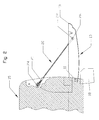
- FIG. 1 is a perspective view of one embodiment of a truck bed with a tailgate in a conventional open position
- FIG. 2 is a left side elevation view of a conventional tailgate in the conventional open position
- FIG. 3 is a left side elevation view of a tailgate in the fully open position using fixed length extension links in accordance with the present invention
- FIG. 4 is a left side elevation view of a tailgate in the fully open position using adjustable length extension links in accordance with the present invention
- FIG. 5 shows detailed right side elevation and front elevation views of one embodiment of a fixed length extension link in accordance with the present invention
- FIG. 6 shows detailed right side elevation and front elevation views of one embodiment of an adjustable length extension link in accordance with the present invention
- FIG. 7 shows detailed right side elevation and front elevation views of the fixed length extension link of FIG. 5 installed on a tailgate support in accordance with the present invention
- FIG. 8 shows detailed right side elevation and front elevation views of one embodiment of a spring keeper or lock and a keeper release lever for use in connection with an extension link in accordance with the present invention
- FIG. 9 is a front elevation view of a detachable clip end of a conventional tailgate support connected to a stud and fitted with one embodiment of a keeper release lever or first actuator in accordance with the present invention
- FIG. 10 is a right side elevation view of the stud, detachable clip end, and keeper release lever of FIG. 9 with the keeper or first lock in the first position;
- FIG. 11 is a right side elevation view of the stud, detachable clip end, and keeper release lever of FIGS. 9 and 10 with the keeper release lever depressed or in the second position;
- FIG. 12 shows detailed left side elevation and front elevation views of a detachable clip end of a tailgate support fitted with one embodiment of a keeper release lever in accordance with the present invention
- FIG. 13 shows detailed right side elevation and front elevation views of an alternate embodiment of a fixed length extension link in accordance with the present invention
- FIG. 14 shows detailed right side elevation and front elevation views of the extension link of FIG. 13 installed in between a stud and the detachable clip end of a tailgate support in accordance with the present invention
- FIG. 15 is a schematic diagram illustrating the loading of an ATV with a tailgate in a conventional open position
- FIG. 16 is a schematic diagram illustrating the loading of an ATV with a tailgate lowered in accordance with the present invention.
- FIG. 17 is a schematic diagram illustrating the loading of a riding lawn mower with a tailgate in a conventional open position
- FIG. 18 is a schematic diagram illustrating the loading of a riding lawn mower with a tailgate lowered in accordance with the present invention.
- FIG. 19 is a schematic diagram illustrating the break-over angle with a tailgate in a conventional open position.
- FIG. 20 is a schematic diagram illustrating the break-over angle with a tailgate lowered in accordance with the present invention.
- side e.g. bed side or side wall
- keeper e.g. first lock
- stud e.g. first stud
- male end stud e.g. second stud
- keeper release lever e.g. second actuator
- keeper release lever e.g. first actuator
- the bed 15 of a vehicle may include a tailgate 10 , two sides 17 , two tailgate supports 20 , and a bed floor 16 .
- a tailgate 10 may be pivotable about a tailgate pivot 11 and have a pivot edge 12 and a leading or top edge 13 .
- the tailgate 10 may be supported or suspended in the open position by the tailgate supports 20 , which are typically cable assemblies comprising an easily detachable, clip end 21 , a cable 25 , and a fixed end 22 .
- the detachable clip ends 21 may comprise a female end opening 21 a or aperture 21 a and a keeper 23 . These ends 21 may be attached to tailgate support studs 24 located on the bed sides 17 .
- the fixed end 22 of a tailgate support 20 may be attached to a tailgate side 14 by a bolt 26 .
- the tailgate 10 may be pivotable about a tailgate pivot 11 between a generally vertical closed or first position and an open or second position.
- an extension link 30 in accordance with the present invention may form a tailgate-lowering apparatus 30 .
- An extension link 30 may be placed between a tailgate support 20 and a tailgate support stud 24 .
- Such an assembly may allow the leading or top edge 13 of a tailgate 10 to be lowered to a fully open position lower than a conventional open position, which is about ninety degrees of rotation from the closed position.
- an extension link 30 may comprise a fixed length extension link 30 a having a fixed length extension link body 34 , a male end stud 31 , a female end opening 32 or aperture 32 , and a spring keeper or lock assembly 33 .
- These components 31 , 32 , 33 , 34 may be formed of any suitable materials. In certain embodiments, these components 31 , 32 , 33 , 34 may be formed of metal.
- a male end stud 31 may be nearly identical to, or substantially a duplicate of, a tailgate support stud 24 located on the bed side 17 .
- the stud 31 may be located proximate one end of the link body 34 .
- a female end opening 32 may be nearly identical to, or substantially a duplicate of, the opening on the detachable clip end 21 of a tailgate support 20 .
- the opening 32 may be located proximate an end of the link body 34 , opposite the stud 31 .
- the distance between the stud 31 and the opening 32 may be selected such that when installed, a loaded tailgate 10 may not contact an underlying bumper 18 .
- an extension link 30 may comprise an adjustable length extension link 30 b having an adjustable length extension link body 37 , a male end stud 31 , a female end opening 32 , and a spring keeper assembly 33 .
- the male end stud 31 may be nearly identical to, or substantially a duplicate of, the tailgate support stud 24 located on the bed side 17 .
- the stud 31 may be selectively located in one of a plurality of stud locating positions 39 distributed across or along a stud locating opening 38 or aperture 38 .
- a male end stud nut 36 or other fastener may engage the stud 31 to lock it in place.
- the female end opening 32 or aperture 32 of an adjustable length extension link 30 b may be nearly identical to, or substantially a duplicate of, the opening on a detachable clip end 21 of a tailgate support 20 .
- the opening 32 may be located proximate an end of the link body 37 , opposite the stud 31 .
- the distance between the stud 31 and the opening 32 may be selected such that when installed, a loaded tailgate 10 may not contact an underlying bumper 18 . If after inspection, changes to the distance between the stud 31 and the opening 32 are necessary, the nut 36 may be loosen, the location of the stud 31 may be changed, and the nut 36 may be retightened. In this manner, extension links 30 of a single manufacture may be suitable for installation in a variety of vehicles of different dimensions and geometries.
- Extension links 30 in accordance with the present invention may be configured to minimize any undesirable wear on the vehicle of a user.
- the side edges 34 a of an extension link 30 may be coated with a rubber like material to protect the paint on a corresponding vehicle.
- a spring keeper or lock assembly 33 may comprise a spring keeper 33 a formed of spring steel and a keeper release lever 33 b .
- a spring keeper assembly 33 may be mounted to either a fixed length extension link body 34 or an adjustable length extension link body 37 .
- a spring keeper 33 a may assist in maintaining the connection between an extension link 30 and a stud 24 .
- a keeper release lever 33 b may be formed in a manner such that when the thumb depressing end 61 is depressed, the keeper release end 62 may pivot about a release lever pivot point 63 and away from the stud 24 . Accordingly, by depressing one end 61 of the spring keeper assembly 33 , a corresponding extension link 30 may be easily removed from an associated stud 24 .
- selected embodiments in accordance with the present invention may include one or more keeper release levers 60 .
- These keeper release levers 60 may be provided on OEM tailgate supports 20 or retrofit onto keepers 23 mounted on the detachable clip ends 21 of tailgate supports 20 that are already installed on a vehicle.
- a keeper release lever 60 may be formed so that when the thumb depressing end 61 is depressed the keeper release end 62 may pivot about the release lever pivot point 63 and away from the stud 24 . Accordingly, by depressing one end 61 of the keeper release lever 60 , a corresponding tailgate support 20 may be easily removed from an associated stud 24 , 31 .
- tailgate supports 20 in the form of cable assemblies with detachable clip ends 22 and keepers 23
- other embodiments in accordance with the present invention may be well suited to other commonly found forms of tailgate support members 20 .
- the extension link 30 illustrated in the provided detailed right side elevation and front elevation views may be a suitable alternative when such alternative studs 24 are encountered.
- embodiments in accordance with the present invention lower the leading or top edge 13 of the tailgate 10 . This may result in a reduction in the incline of loading ramps 51 used when loading items such as motorcycles, ATV's 52 , small tractors, or the like into the bed of a vehicle. By reducing the angle 42 of the loading ramps 51 , it may be easier and safer to load and unload such items.
- a tailgate 10 with a lower leading edge 13 may facilitate loading of items with low ground clearance (e.g., riding lawn mowers 53 ). Such items would normally hang on the leading edge 13 of a conventional tailgate 10 at the location where the loading ramps 51 rest. However, in embodiments in accordance with the present invention, when the leading edge 13 of the tailgate 10 is lowered below the plane of the bed 16 , both the incline of the loading ramps 51 and the break-over angle 41 are reduced.
- the break-over angle 41 may be defined as the angle between the plane of the tailgate 10 extended rearward and the angle of the loading ramp(s) 51 .
- the angle that a tailgate 10 rotates down from the conventional open position to fully open position in accordance with the present invention may be referred to as the tailgate decline angle 43 . Accordingly, between the tailgate decline angle 43 and the reduced break-over angle 41 , embodiments in accordance with the present invention may provide a more gradual transition from ground to bed 16 .
Abstract
Description
Claims (20)
Priority Applications (1)
| Application Number | Priority Date | Filing Date | Title |
|---|---|---|---|
| US12/582,778 US8070206B2 (en) | 2009-10-21 | 2009-10-21 | Tailgate lowering apparatus and method |
Applications Claiming Priority (1)
| Application Number | Priority Date | Filing Date | Title |
|---|---|---|---|
| US12/582,778 US8070206B2 (en) | 2009-10-21 | 2009-10-21 | Tailgate lowering apparatus and method |
Publications (2)
| Publication Number | Publication Date |
|---|---|
| US20110089711A1 US20110089711A1 (en) | 2011-04-21 |
| US8070206B2 true US8070206B2 (en) | 2011-12-06 |
Family
ID=43878721
Family Applications (1)
| Application Number | Title | Priority Date | Filing Date |
|---|---|---|---|
| US12/582,778 Expired - Fee Related US8070206B2 (en) | 2009-10-21 | 2009-10-21 | Tailgate lowering apparatus and method |
Country Status (1)
| Country | Link |
|---|---|
| US (1) | US8070206B2 (en) |
Cited By (3)
| Publication number | Priority date | Publication date | Assignee | Title |
|---|---|---|---|---|
| US20130175820A1 (en) * | 2010-07-05 | 2013-07-11 | Dean LePage | Truck bed extension |
| US9956995B1 (en) * | 2017-01-06 | 2018-05-01 | Fca Us Llc | Drop tailgate with integrated step |
| US10703421B2 (en) | 2018-06-29 | 2020-07-07 | Fca Us Llc | Tailgate overrotation mechanism |
Families Citing this family (4)
| Publication number | Priority date | Publication date | Assignee | Title |
|---|---|---|---|---|
| US9278718B1 (en) * | 2015-03-12 | 2016-03-08 | Ford Global Technologies, Llc | Anti-theft device for tailgates |
| US11220301B2 (en) * | 2018-11-13 | 2022-01-11 | Rivian Ip Holdings, Llc | Multi-position tailgate for a vehicle |
| US11679817B2 (en) * | 2021-08-12 | 2023-06-20 | Hyundai Motor Company | Folding tailgate for a vehicle |
| US11919576B2 (en) * | 2022-03-23 | 2024-03-05 | Rivian Ip Holdings, Llc | Panel systems, structures, and vehicles having an adjustable cable |
Citations (6)
| Publication number | Priority date | Publication date | Assignee | Title |
|---|---|---|---|---|
| US563173A (en) * | 1896-06-30 | End-gate and fastening device therefor | ||
| US659575A (en) * | 1900-08-02 | 1900-10-09 | Wesley Carpenter | End-gate for wagons. |
| US5934727A (en) * | 1997-07-16 | 1999-08-10 | General Motors Corporation | Adaptable pick up truck configuration |
| US6267429B1 (en) * | 2000-10-27 | 2001-07-31 | Ford Global Technologies, Inc. | Multi-position vehicle tailgate assembly |
| US6450559B1 (en) * | 2001-01-22 | 2002-09-17 | General Motors Corporation | Dual position endgate cable post assembly |
| US6951358B1 (en) * | 2004-03-23 | 2005-10-04 | Cable Manufacturing & Assembly, Inc. | Insert for a tailgate cable assembly and a tailgate cable assembly incorporating the same |
-
2009
- 2009-10-21 US US12/582,778 patent/US8070206B2/en not_active Expired - Fee Related
Patent Citations (6)
| Publication number | Priority date | Publication date | Assignee | Title |
|---|---|---|---|---|
| US563173A (en) * | 1896-06-30 | End-gate and fastening device therefor | ||
| US659575A (en) * | 1900-08-02 | 1900-10-09 | Wesley Carpenter | End-gate for wagons. |
| US5934727A (en) * | 1997-07-16 | 1999-08-10 | General Motors Corporation | Adaptable pick up truck configuration |
| US6267429B1 (en) * | 2000-10-27 | 2001-07-31 | Ford Global Technologies, Inc. | Multi-position vehicle tailgate assembly |
| US6450559B1 (en) * | 2001-01-22 | 2002-09-17 | General Motors Corporation | Dual position endgate cable post assembly |
| US6951358B1 (en) * | 2004-03-23 | 2005-10-04 | Cable Manufacturing & Assembly, Inc. | Insert for a tailgate cable assembly and a tailgate cable assembly incorporating the same |
Non-Patent Citations (1)
| Title |
|---|
| 2005 Chevrolet Colorado Owner Manual, General Motors Corporation, pp. 1, 2, 83, 92 and 93. |
Cited By (4)
| Publication number | Priority date | Publication date | Assignee | Title |
|---|---|---|---|---|
| US20130175820A1 (en) * | 2010-07-05 | 2013-07-11 | Dean LePage | Truck bed extension |
| US9108687B2 (en) * | 2010-07-05 | 2015-08-18 | Dean LePage | Truck bed extension |
| US9956995B1 (en) * | 2017-01-06 | 2018-05-01 | Fca Us Llc | Drop tailgate with integrated step |
| US10703421B2 (en) | 2018-06-29 | 2020-07-07 | Fca Us Llc | Tailgate overrotation mechanism |
Also Published As
| Publication number | Publication date |
|---|---|
| US20110089711A1 (en) | 2011-04-21 |
Similar Documents
| Publication | Publication Date | Title |
|---|---|---|
| US8087710B2 (en) | Multi-position tailgate support apparatus and method | |
| US8070206B2 (en) | Tailgate lowering apparatus and method | |
| US8075038B2 (en) | Multi-position tailgate support apparatus and method | |
| US8070208B2 (en) | Multi-position tailgate adjustment apparatus and method | |
| US10391945B2 (en) | Ramp bracket | |
| DK2830929T3 (en) | Foldable vehicle cabin frame | |
| AU2011205003B2 (en) | Fifth wheel hitch retention system | |
| US9694758B1 (en) | Tiltable hauling device | |
| US20120223541A1 (en) | Tailgate gap cover | |
| US10323735B2 (en) | Tailgate and door adjustors | |
| US8070207B2 (en) | Multi-position tailgate support apparatus and method | |
| US20130015218A1 (en) | Apparatus for Connecting a Carrier to a Hardtop | |
| US10486611B1 (en) | Assembly and adapter for supporting an apparatus on a vehicle tow hitch assembly | |
| US10351039B2 (en) | Ramp member | |
| US10525863B2 (en) | Pick-up truck winch apparatus | |
| US20090224566A1 (en) | Floor mat for loading platform and vehicle equipped with it | |
| US20040178242A1 (en) | Cargo carrier for a vehicle | |
| AU2016333142B2 (en) | A wheel support for a vehicle | |
| FR3037311A1 (en) | DEVICE FOR HANGING A TRAILER TO A TRACTOR VEHICLE AND ASSEMBLY FORMED BY THE COUPLING OF A TRACTOR VEHICLE AND A TRAILER COMPRISING SUCH A DEVICE | |
| US8403394B2 (en) | Pickup truck tailgate accessory drill-less adapter | |
| US10486609B2 (en) | Adapter for supporting an apparatus on a vehicle tow high assembly | |
| US20170100994A1 (en) | Vehicle tailgate assembly | |
| CA2814146C (en) | Load stabilizing insert for vehicle springs | |
| CN113715923A (en) | Rotary spare tire lifting system | |
| AU2017261546B1 (en) | Vehicle wheel carrier |
Legal Events
| Date | Code | Title | Description |
|---|---|---|---|
| ZAAA | Notice of allowance and fees due |
Free format text: ORIGINAL CODE: NOA |
|
| ZAAB | Notice of allowance mailed |
Free format text: ORIGINAL CODE: MN/=. |
|
| STCF | Information on status: patent grant |
Free format text: PATENTED CASE |
|
| AS | Assignment |
Owner name: CRZ, INC. DOING BUSINESS AS (D.B.A.) RIDER TAILGAT Free format text: ASSIGNMENT OF ASSIGNORS INTEREST;ASSIGNOR:ZIELINSKY, CARY R.;REEL/FRAME:027476/0788 Effective date: 20111230 |
|
| FPAY | Fee payment |
Year of fee payment: 4 |
|
| FEPP | Fee payment procedure |
Free format text: ENTITY STATUS SET TO MICRO (ORIGINAL EVENT CODE: MICR); ENTITY STATUS OF PATENT OWNER: MICROENTITY |
|
| MAFP | Maintenance fee payment |
Free format text: PAYMENT OF MAINTENANCE FEE, 8TH YEAR, MICRO ENTITY (ORIGINAL EVENT CODE: M3552); ENTITY STATUS OF PATENT OWNER: MICROENTITY Year of fee payment: 8 |
|
| FEPP | Fee payment procedure |
Free format text: MAINTENANCE FEE REMINDER MAILED (ORIGINAL EVENT CODE: REM.); ENTITY STATUS OF PATENT OWNER: MICROENTITY |
|
| LAPS | Lapse for failure to pay maintenance fees |
Free format text: PATENT EXPIRED FOR FAILURE TO PAY MAINTENANCE FEES (ORIGINAL EVENT CODE: EXP.); ENTITY STATUS OF PATENT OWNER: MICROENTITY |
|
| STCH | Information on status: patent discontinuation |
Free format text: PATENT EXPIRED DUE TO NONPAYMENT OF MAINTENANCE FEES UNDER 37 CFR 1.362 |
|
| FP | Lapsed due to failure to pay maintenance fee |
Effective date: 20231206 |