US8069769B2 - Portable protection device - Google Patents
Portable protection device Download PDFInfo
- Publication number
- US8069769B2 US8069769B2 US12/257,902 US25790208A US8069769B2 US 8069769 B2 US8069769 B2 US 8069769B2 US 25790208 A US25790208 A US 25790208A US 8069769 B2 US8069769 B2 US 8069769B2
- Authority
- US
- United States
- Prior art keywords
- truss
- frames
- protection device
- portable
- ballistic
- Prior art date
- Legal status (The legal status is an assumption and is not a legal conclusion. Google has not performed a legal analysis and makes no representation as to the accuracy of the status listed.)
- Expired - Lifetime, expires
Links
Images







Classifications
-
- E—FIXED CONSTRUCTIONS
- E04—BUILDING
- E04H—BUILDINGS OR LIKE STRUCTURES FOR PARTICULAR PURPOSES; SWIMMING OR SPLASH BATHS OR POOLS; MASTS; FENCING; TENTS OR CANOPIES, IN GENERAL
- E04H9/00—Buildings, groups of buildings or shelters adapted to withstand or provide protection against abnormal external influences, e.g. war-like action, earthquake or extreme climate
- E04H9/04—Buildings, groups of buildings or shelters adapted to withstand or provide protection against abnormal external influences, e.g. war-like action, earthquake or extreme climate against air-raid or other war-like actions
- E04H9/10—Independent shelters; Arrangement of independent splinter-proof walls
-
- F—MECHANICAL ENGINEERING; LIGHTING; HEATING; WEAPONS; BLASTING
- F41—WEAPONS
- F41H—ARMOUR; ARMOURED TURRETS; ARMOURED OR ARMED VEHICLES; MEANS OF ATTACK OR DEFENCE, e.g. CAMOUFLAGE, IN GENERAL
- F41H5/00—Armour; Armour plates
- F41H5/013—Mounting or securing armour plates
-
- F—MECHANICAL ENGINEERING; LIGHTING; HEATING; WEAPONS; BLASTING
- F41—WEAPONS
- F41H—ARMOUR; ARMOURED TURRETS; ARMOURED OR ARMED VEHICLES; MEANS OF ATTACK OR DEFENCE, e.g. CAMOUFLAGE, IN GENERAL
- F41H5/00—Armour; Armour plates
- F41H5/06—Shields
- F41H5/08—Shields for personal use, i.e. hand held shields
-
- F—MECHANICAL ENGINEERING; LIGHTING; HEATING; WEAPONS; BLASTING
- F41—WEAPONS
- F41H—ARMOUR; ARMOURED TURRETS; ARMOURED OR ARMED VEHICLES; MEANS OF ATTACK OR DEFENCE, e.g. CAMOUFLAGE, IN GENERAL
- F41H5/00—Armour; Armour plates
- F41H5/24—Armour; Armour plates for stationary use, e.g. fortifications ; Shelters; Guard Booths
-
- F—MECHANICAL ENGINEERING; LIGHTING; HEATING; WEAPONS; BLASTING
- F42—AMMUNITION; BLASTING
- F42D—BLASTING
- F42D5/00—Safety arrangements
- F42D5/04—Rendering explosive charges harmless, e.g. destroying ammunition; Rendering detonation of explosive charges harmless
- F42D5/045—Detonation-wave absorbing or damping means
Definitions
- the present invention relates to a portable protection system that can be assembled to establish a protective barrier to a threat, such as a ballistic projectile, a blast, or other such threat. More specifically, the present invention relates to a modular portable structure adapted to carry an armor layer to form a protective wall.
- a “ballistic” material is defined as having the property of stopping, or severely retarding the progress of, a projectile. However, it will be understood that a ballistic shield may not be completely impenetrable to all types of projectiles under all situations.
- a holding member is disposed on at least one of the first and second frames for releasably engaging the protection member.
- the protection member includes a panel fabricated from a protective material, such as for example, a ballistic material.
- the protection member further includes suitable connectors to engage the holding member, thereby allowing the panel to be releasably secured to the truss.
- the panel further includes a window adapted to allow selective access through the panel.
- at least one roof protection member is selectively securable to the truss in an overhead configuration, so as to form a roof structure.
- FIG. 3 is a partially exploded perspective view of the truss of FIG. 2 , showing the truss in a collapsed position with the first wall frame exploded from the second wall frame;
- FIG. 5 is a perspective view of an expandable support member of the truss of FIG. 4 , showing the expandable support member in an expanded position;
- FIG. 7 is a perspective view of the embodiment of the truss of FIG. 4 , showing the truss in a collapsed position;
- FIG. 8 is a perspective view of an expandable support member of the frame of FIG. 4 , showing the expandable support member in a collapsed position;
- FIG. 9 is an enlarged partial perspective view of an expandable support member and accompanying lock
- FIG. 11 is a partial perspective view of a portion of the truss of FIG. 4 , showing the hollow piece, post, and lock portions of the truss, with the post received within the hollow piece;
- FIG. 12 is a partial perspective view of a protection member of one embodiment of the present invention, showing the window in a closed position;
- FIG. 13 is a partial perspective view of a protection member of one embodiment of the present invention, showing the window in an open position;
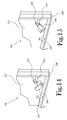
- FIG. 14 is a partial perspective view of a holding member of the truss illustrated in FIG. 2 , showing the connector of a protection member engaging the holding member in a free position;
- FIG. 15 is a partial perspective view of the holding member of FIG. 14 , showing the connector of a protection member engaging the holding member in an abutted position;
- FIG. 16 is a perspective view showing another embodiment of the portable protection system.
- FIG. 20 is a perspective view showing another embodiment of the portable protection system.
- FIG. 1 illustrates a portable protection system according to one embodiment of the present invention.
- the portable protection system, or system is identified as 10 herein and in the accompanying figures.
- the portable protection system 10 includes generally a selectively collapsible and expandable truss 100 which, when configured to an expanded position, is adapted to carry and support at least one protection member 102 .
- the truss 100 is fabricated from a substantially rigid material, such as aluminum, steel, fiber reinforced composite, polymer, or the like. As will be discussed in further detail below, the truss 100 is adapted to be selectively configured between an expanded position and a collapsed position.
- a plurality of central braces 160 are provided, with at least one central brace 160 extending between the first opposing inner surfaces 152 , 154 , thereby dividing each wall frame 106 , 108 into two partitions.
- the first side members 118 of each of the wall frames 106 , 108 include second opposing inner surfaces 162 , 164 and the second side members 120 of each of the wall frames 106 , 108 include third opposing inner surfaces 166 , 168 .
- a second support frame 112 extends between the second side members 120 of the first and second wall frames 106 , 108 .
- a third support frame 114 extends between the first end members 122 of the first and second wall frames 106 , 108 , and a fourth support frame 116 , extends between the second end members 124 of the first and second wall frames 106 , 108 .
- Those skilled in the art will recognize numerous configurations for the support frames which are suitable for maintaining the first and second wall frames 106 , 108 in position proximate one another, and such configurations may be used without departing from the spirit and scope of the present invention.
- the truss 100 is adapted to be selectively collapsed and expanded.
- the first and second wall frames 106 , 108 are adapted to be selectively repositionable proximate one another between the expanded position and the collapsed position.
- each of the support frames 110 , 112 , 114 , 116 is selectively secured to the first wall frame 106 in the expanded position by a releasable fastener, such as a latch, a hook and loop fastener, a nut and bolt assembly, or other such releasable fastener.
- a releasable fastener such as a latch, a hook and loop fastener, a nut and bolt assembly, or other such releasable fastener.
- each of the support frames 110 , 112 , 114 , 116 is selectively rotated about an adjoining hinge 104 against the second wall frame 108 , thereby allowing the first and second wall frames 106 , 108 to be selectively stacked in a collapsed position, with each of the support frames 110 , 112 , 114 , 116 disposed in a substantially coplanar configuration therebetween.
- each of the support frames 110 , 112 , 114 , 116 is selectively secured to both first and second wall frames 106 , 108 in the expanded position by releasable fasteners, such that the truss 100 is selectively collapsable by disconnecting each of the support frames 110 , 112 , 114 , 116 from the wall frames 106 , 108 and stacking the various support frames and wall frames.
- FIGS. 4-10 illustrate another embodiment of the truss 100 a .
- the truss 100 a is selectively collapsible and expandable absent the selective disconnection of either of the wall frames 106 , 108 from any of the support frames 110 a , 112 a , 114 a , 116 a .
- each support frame 110 a , 112 a , 114 a , 116 a is defined by an expandable support member.
- the first gate 180 is rotatable proximate the second gate 182 about the first hinge 184 into a stacked configuration when the truss 100 a is collapsed (see FIGS. 7 and 8 ) and into a side-by-side configuration when the truss 100 a is expanded (see FIGS. 4 and 5 ).
- Support braces 193 extend between the opposite ends 194 , 196 of each gate 180 , 182 .
- Each gate 180 , 182 defines an overlap extension 195 which engages an adjoining gate when the gates 180 , 182 are rotated to the side-by-side expanded position.
- a lock 130 is provided at each opposite end 194 , 196 of each gate 180 , 182 for engaging the overlap extension 195 to releasably lock the gates 180 , 182 in the expanded position.
- FIG. 9 shows a portion of a support frame 110 a cut out to show one of the locks 130 .
- each of the opposite ends 194 , 196 of each gate 180 , 182 defines a through bore 150 .
- Each lock 130 includes a housing 134 disposed on a cooperating gate end 194 , 196 proximate the through bore 150 .
- a pin 132 is also included which is spring-biased to extend through the through bore 150 .
- Each overlap extension 195 defines a cooperating through opening 144 which is configured to substantially align with the through bore 150 of the cooperating gate end 194 , 196 when the gates 180 , 182 are rotated to the side-by-side expanded position. In this configuration, extension of the pin 132 through a through bore 150 and cooperating opening 144 serves to lock each respective gate 180 , 182 in the side-by-side expanded position.
- a ring 136 is secured to each spring-biased pin 132 to maintain the pin 132 within its housing 134 against the bias of the spring, and to allow for selective withdrawal of the pin 132 from the through bore 150 .
- the housing 134 is provided with a plurality of slots 138 adapted to receive the ring 136 and allow the pin 132 to slide from within the housing 134 through the through bore 150 .
- the pin 132 is released from the through bore 150 by withdrawing the ring 136 from the slots 138 and turning the ring 136 until the ring 136 engages a plurality of indents 146 of the housing 134 , thereby allowing the pin 132 to remain retracted from the through bore 150 .
- the lock 130 is selectively lockable and unlockable so as to allow the first and second frame portions 106 , 108 to be selectively secured in the collapsed position.
- first and second frame portions 106 , 108 to be selectively secured in the collapsed position.
- fasteners, frictional engagement, and the like any device and configurations suitable for selectively locking and unlocking the first and second frame portions 106 , 108 in the collapsed position, including but not limited to fasteners, frictional engagement, and the like, and such devices and configurations may be used without departing from the spirit and scope of the present invention.
- first, second, third, and fourth expandable members 110 , 112 , 114 , and 116 can be any expandable or expansion member for collapsing and expanding the truss 100 .
- a single gate is pivotally attached to one of the frame portions and pivots inwardly or outwardly when the frame is collapsed.
- other expandable/expansion members can be employed without departing from the spirit and scope of the present invention, including telescoping members, twist locking cylinders, pivotally interconnected struts, springs, and the like.
- At least one lock 130 is disposed between the first frame 106 and the second frame 108 to selectively lock the first frame 106 in the collapsed position proximate the second frame 108 .
- a hollow piece 126 is disposed at each corner of the first frame 106 and is configured to extend cantilevered toward the second frame 108 .
- Each cantilevered end 128 of each hollow piece 126 is provided with a lock 130 .
- a post 148 is provided to extend from the second frame 108 toward the first frame 106 in such a configuration that each post 148 is adapted to be received within and engage a cooperating hollow piece 126 .
- Each lock 130 mounted on each hollow piece 126 is adapted to engage a cooperating post 148 to selectively join the post 148 to the hollow piece 126 , thereby securing the second frame 108 proximate the first frame 106 when the truss 100 is in the collapsed position.
- each hollow piece 126 defines a through bore 150 .
- each lock 130 includes a housing 134 disposed on a cooperating through bore 150 , and each lock 130 further includes a pin 132 which is spring-biased to extend through the through bore 150 .
- Each post 148 defines a cooperating opening 144 which is configured to substantially align with the through bore 150 of the cooperating hollow piece 126 when the post 148 is received within the hollow piece 126 (see FIG. 11 ).
- selective extension of the pin 132 through a through bore 150 and cooperating opening 144 serves to selectively lock each respective post 148 within each cooperating hollow piece 126 .
- Each panel 172 is adapted to be releasably secured to the truss 100 to form the armored wall system 10 .
- each panel 172 is substantially rectangular in shape and defines beveled sections 173 along two adjacent edges of the panel 172 and flat sections 175 along the remaining two edges of the panel 172 .
- each beveled section 173 of a panel 172 is adapted to overlap with the corresponding flat edge 175 of an adjacent panel 172 , such that the seams between adjacent panels 172 are substantially covered and reinforced by the beveled sections 173 .
- each protection member 102 includes suitable connectors 202 disposed on at least one planar surface of the panel 172 to allow the panel 172 to be releasably secured to at least a portion of the holding members 174 of one of the first and second frames 106 , 108 .
- a plurality of hooks 202 are disposed along one surface of the panel 172 .
- the hooks 202 are configured to engage at least one of the holding members 174 to secure the protection member 102 to one of the first and second frames 106 , 108 .
- An elongated pivotal member 204 is provided proximate at least one hook 202 . As shown in FIGS. 14 and 15 , the pivotal member 204 is configured to allow for selective rotation along the panel 172 between a free position ( FIG. 14 ) and an abutted position ( FIG. 15 ).
- each pivotal member 204 Upon engagement of the hooks 202 with cooperating holding members 174 , each pivotal member 204 is selectively positionable to the abutted position, whereby the rotatable member provides a stop to prevent a cooperating holding member 174 from disengaging a cooperating hook 202 .
- the rotatable member 204 provides a means to selectively lock and unlock the releasable engagement of the protection member 102 to the truss 100 .
- the protection members 174 are sized to substantially cover one partition of one of the first and second frames 106 , 108 .
- Multiple holding members 174 are located within each partition of the first and second frames 106 , 108 .
- cooperating holding members 174 located within one partition support one protection member 102
- cooperating holding members 174 located within another partition support at least one other protection member 102 .
- the size of the protection members 174 may vary without departing from the spirit and scope of the present invention.
- a portion of the holding members 174 disposed within one partition cooperate to support one protection member 102
- another portion of the holding members 174 disposed within the partition cooperate to support at least one other protection member 102
- all holding members 174 provided on one of the first and second frames 106 , 108 cooperate to support a single protection member 102 .
- At least one protection member 102 includes a window 216 .
- the window 216 is sized and shaped to allow a user at least visible access to a portion of the environment beyond the panel 172 .
- the window 216 includes a portal 218 defined by the panel 172 .
- a window pane 220 is selectively securable within the portal to allow a user selective access through the portal 218 .
- the window pane 220 is hinged along one edge 222 of the portal 218 , and a suitable fastener 228 is provided to secure the window pane 220 in a closed position within the portal 218 , such that the window 216 is selectively openable and closable.
- the window pane 220 is fabricated from a ballistic material substantially similar to the panel 172 such as for example, steel, ballistic ceramic, ballistic polymer, or other such material.
- the window pane 220 is fabricated from a transparent ballistic armor, such as glass-ceramic, transparent ballistic polymer, borosilicate glass, tempered glass, or other such transparent material.
- a window pane 220 of transparent ballistic armor is fixed within the portal 218 , while an opaque selectively openable and closable door is provided to selectively cover the window pane 220 and to allow selective observation through the fixed, transparent, ballistic armor window pane.
- protection members 102 which may be combined and mounted on the front or back of the truss 100 , or both, depending on the threat level. For example, if the threat level is small arms, a ceramic tile panel mounted on the front of the truss 100 may be sufficient. Referring to FIG. 21 , for heavier arms threat, multiple-layered protection members 102 can be mounted on the front of the truss 100 with a fragmentation blanket 500 mounted on the back. In several more discreet embodiments, such as the embodiment illustrated in FIG.
- the interior space of the truss 100 is adapted to contain a dispersive material, such as sand bags or other such containers filled with concrete, rocks, water, gels, thickening fluids, or other such dispersive materials.
- a dispersive material such as sand bags or other such containers filled with concrete, rocks, water, gels, thickening fluids, or other such dispersive materials.
- at least one sand bag 502 is provided within the interior of the truss 100 .
- at least one hanger 504 is provided for hanging at least one sand bag in an elevated position within the truss 100 .
- additional holding members 174 are provided on each of the second and third opposing inner surfaces 162 , 164 , 166 , 168 of the first and second frames 106 , 108 . As shown in FIG. 16 , these additional holding members 174 are adapted to releasably support at least one end protection member 300 between the first and second frames 106 , 108 .
- the end protection member 300 serves to enclose a portion of the interior of the truss 100 between the first and second wall frames 106 , 108 to provide additional ballistic protection to the interior of the truss 100 , as well as to provide additional structural support to the system 10 .
- inclusion of the end protection members 300 is not necessary to accomplish the present invention.
- FIG. 17 illustrates an additional feature of several embodiments of the present invention.
- a stanchion 302 is provided to support the truss 100 in a substantially upright position.
- the stanchion includes a substantially rigid upright beam 304 adapted to be secured to the truss 100 along at least one of the first and second side members 118 , 120 of the wall frames 106 , 108 .
- a floor beam 306 is provided having a proximal end 308 fixed to the upright beam 304 and a distal end 310 which extends from the upright beam 304 toward a floor surface, such as the ground or other floor surface. The floor beam 306 engages the floor surface to secure the upright beam 304 in a substantially upright configuration proximate the floor surface.
- the proximal end 308 of the floor beam 306 is secured to a bottom end 312 of the upright beam 304 , thereby allowing the floor beam 306 to extend orthogonally from the upright beam 304 along the floor surface to support the upright beam 304 in the upright configuration.
- an orthogonal relationship between the upright beam 304 and the floor beam 306 is not necessary to accomplish the present invention.
- the proximal end 308 of the floor beam 306 is secured to an upper portion of the upright beam 304 , and the floor beam 306 extends downward at an acute angle to the upright beam 304 to contact the floor surface.
- the distal end 310 of the floor beam 306 defines a through opening 314 .
- a stake 316 is adapted to be received by the through opening 314 and driven into the floor surface in order to secure the stanchion in place proximate the floor surface.
- connectors suitable for securing the stanchion 302 proximate a floor surface may be used without departing from the spirit and scope of the present invention.
- Each truss 100 includes a means for engaging an adjacent truss 100 .
- the first and second wall frames 106 , 108 are provided with a plurality of holes 508 .
- Each hole 508 is configured to substantially align with a corresponding hole of an adjacent truss 100 .
- each hole 508 is adapted to receive a standard connector, such as a bolt, screw, pin, or other suitable connector.
- the connector 206 includes a bracket 208 defining an opening 210 configured to align with a pin 510 disposed on an adjacent truss 100 .
- the bracket 208 extends generally outwardly from the truss 100 away from the support frames 110 , 112 , 114 , 116 .
- the pins 510 are adapted to be received within the openings 210 to secure the trusses 100 in an adjacent configuration.
- the connectors 206 are disposed on the support frames 110 , 112 , 114 , 116 , however, it will be understood that the connectors 206 can be alternatively provided on the wall frame portions 106 , 108 of the truss 100 without departing from the spirit and scope of the present invention. Furthermore, it will be understood that, as alternatives to brackets 208 and pins 510 , any known connectors, such as bolts, hooks, clips, latches, ties, and the like, can be used to gang multiple trusses 100 together.
- FIG. 18 illustrates a protection wall 12 formed by adjoining multiple systems 10 to form a three-sided structure.
- a roof structure 400 is provided to cover the interior of the protection wall 12 and provide ballistic protection from overhead ballistic threats.
- the roof structure 400 includes a roof truss 402 having mounting rails 404 adapted to be secured to at least one of the first and second end members 122 , 124 of at least one truss 100 .
- the mounting rails 404 carry and support a plurality of roof frames 406 which are secured to the mounting rails 404 in an angled configuration and meet along a central gable 408 .
- the plurality of roof protection members 410 are collectively shaped to form a substantially enclosed roof surface.
- the roof protection members 410 are provided with suitable connectors to releasably engage the roof frames 406 in order to releasably mount the roof protection members 410 to the roof frames 406 .
- the system 10 is adapted to be used for various protection needs including ballistic, blast, and chemical protection. Any number of trusses 100 can be ganged together in various wall configurations to meet any need. Each truss 100 is portable, lightweight, and self-standing. Also, each truss 100 can be rapidly assembled from a collapsed position ( FIG. 3 ) to an expanded position ( FIG. 2 ), and disassembled for storage and transportation.
- the portable protection system 10 of the present invention can be easily moved and quickly set up in any location, and the protection members 102 can be adjusted or changed to meet any threat level. With the above-described system 10 , protection walls can be rapidly and easily set up in any configuration with minimal need for tools.
- the system 10 can also be rapidly disassembled by selectively disconnecting the connectors 206 of the protection members 102 , removing the protection members 102 from each frame, and collapsing the truss 100 . Given the lightweight nature of each truss 100 , the frames can be easily moved to another location to set up another protection wall.
Landscapes
- Engineering & Computer Science (AREA)
- General Engineering & Computer Science (AREA)
- Architecture (AREA)
- Business, Economics & Management (AREA)
- Emergency Management (AREA)
- Environmental & Geological Engineering (AREA)
- Civil Engineering (AREA)
- Structural Engineering (AREA)
- Aiming, Guidance, Guns With A Light Source, Armor, Camouflage, And Targets (AREA)
Priority Applications (14)
| Application Number | Priority Date | Filing Date | Title |
|---|---|---|---|
| US12/257,902 US8069769B2 (en) | 2005-04-25 | 2008-10-24 | Portable protection device |
| EP09822699.6A EP2350555A4 (en) | 2008-10-24 | 2009-10-22 | PORTABLE PROTECTION DEVICE |
| JP2011533329A JP2012506989A (ja) | 2008-10-24 | 2009-10-22 | 可搬式防護デバイス |
| PCT/US2009/061664 WO2010048391A2 (en) | 2008-10-24 | 2009-10-22 | Portable protection device |
| MX2010004115A MX2010004115A (es) | 2008-10-24 | 2009-10-22 | Dispositivo de proteccion portatil. |
| AP2011005708A AP3561A (en) | 2008-10-24 | 2009-10-22 | Portable protection device |
| GB0918606.5A GB2464618B (en) | 2008-10-24 | 2009-10-23 | Portable protection device |
| US12/840,705 US7934444B2 (en) | 2005-04-25 | 2010-07-21 | Portable protection device |
| ZA2011/02511A ZA201102511B (en) | 2008-10-24 | 2011-04-05 | Portable protection device |
| IL212469A IL212469A (he) | 2008-10-24 | 2011-04-26 | מתקן הגנה נייד |
| US13/099,446 US8234967B2 (en) | 2005-04-25 | 2011-05-03 | Portable protection device |
| CO11054173A CO6501146A2 (es) | 2008-10-24 | 2011-05-03 | Dispositivo de proteccion portatil |
| US13/541,037 US9228369B2 (en) | 2005-04-25 | 2012-07-03 | Portable protection device |
| IL235641A IL235641B (he) | 2008-10-24 | 2014-11-11 | מתקן הגנה נייד |
Applications Claiming Priority (2)
| Application Number | Priority Date | Filing Date | Title |
|---|---|---|---|
| US11314905A | 2005-04-25 | 2005-04-25 | |
| US12/257,902 US8069769B2 (en) | 2005-04-25 | 2008-10-24 | Portable protection device |
Related Parent Applications (1)
| Application Number | Title | Priority Date | Filing Date |
|---|---|---|---|
| US11314905A Continuation-In-Part | 2005-04-25 | 2005-04-25 |
Related Child Applications (1)
| Application Number | Title | Priority Date | Filing Date |
|---|---|---|---|
| US12/840,705 Continuation US7934444B2 (en) | 2005-04-25 | 2010-07-21 | Portable protection device |
Publications (2)
| Publication Number | Publication Date |
|---|---|
| US20100043629A1 US20100043629A1 (en) | 2010-02-25 |
| US8069769B2 true US8069769B2 (en) | 2011-12-06 |
Family
ID=41426601
Family Applications (4)
| Application Number | Title | Priority Date | Filing Date |
|---|---|---|---|
| US12/257,902 Expired - Lifetime US8069769B2 (en) | 2005-04-25 | 2008-10-24 | Portable protection device |
| US12/840,705 Expired - Lifetime US7934444B2 (en) | 2005-04-25 | 2010-07-21 | Portable protection device |
| US13/099,446 Expired - Lifetime US8234967B2 (en) | 2005-04-25 | 2011-05-03 | Portable protection device |
| US13/541,037 Expired - Lifetime US9228369B2 (en) | 2005-04-25 | 2012-07-03 | Portable protection device |
Family Applications After (3)
| Application Number | Title | Priority Date | Filing Date |
|---|---|---|---|
| US12/840,705 Expired - Lifetime US7934444B2 (en) | 2005-04-25 | 2010-07-21 | Portable protection device |
| US13/099,446 Expired - Lifetime US8234967B2 (en) | 2005-04-25 | 2011-05-03 | Portable protection device |
| US13/541,037 Expired - Lifetime US9228369B2 (en) | 2005-04-25 | 2012-07-03 | Portable protection device |
Country Status (10)
| Country | Link |
|---|---|
| US (4) | US8069769B2 (he) |
| EP (1) | EP2350555A4 (he) |
| JP (1) | JP2012506989A (he) |
| AP (1) | AP3561A (he) |
| CO (1) | CO6501146A2 (he) |
| GB (1) | GB2464618B (he) |
| IL (2) | IL212469A (he) |
| MX (1) | MX2010004115A (he) |
| WO (1) | WO2010048391A2 (he) |
| ZA (1) | ZA201102511B (he) |
Cited By (5)
| Publication number | Priority date | Publication date | Assignee | Title |
|---|---|---|---|---|
| US8850949B1 (en) * | 2013-04-25 | 2014-10-07 | Lois A. Lopez | Safety door for classrooms and the like |
| US20160238349A1 (en) * | 2015-02-13 | 2016-08-18 | Defenshield, Inc. | Barrier |
| WO2016154014A1 (en) * | 2015-03-20 | 2016-09-29 | Balllistic Furniture Systems, Inc. | Ballistic barrier partition system and retrofit kit |
| US9615658B1 (en) | 2015-01-05 | 2017-04-11 | Donald Ray Nobles | Desk with a projectile resistant desktop |
| US12410993B2 (en) | 2022-06-07 | 2025-09-09 | Goldeneye Defense Llc | Mobile ballistics and projectile resistant crate with telescoping protective ballistic resistant panels and removable storage cage |
Families Citing this family (41)
| Publication number | Priority date | Publication date | Assignee | Title |
|---|---|---|---|---|
| US7789258B1 (en) * | 2007-05-07 | 2010-09-07 | The United States Of America As Represented By The Secretary Of The Navy | Mobile self-contained networked checkpoint |
| US7856915B1 (en) * | 2007-05-07 | 2010-12-28 | The United States Of America As Represented By The Secretary Of The Navy | Blast mitigating mobile self-contained networked checkpoint |
| MX2009012630A (es) * | 2007-05-25 | 2009-12-07 | Darren S Schulte | Blindaje contra proyectil balistico. |
| US8001740B2 (en) * | 2008-05-30 | 2011-08-23 | Smith Jeffery L | Ballistic and forced entry resistant construction |
| WO2011072374A1 (en) * | 2009-12-14 | 2011-06-23 | Dynamic Shelters Inc . | Tethermast and frag wall |
| US8726780B2 (en) * | 2011-05-18 | 2014-05-20 | Defenshield, Inc. | Barrier |
| US9222759B2 (en) | 2011-05-18 | 2015-12-29 | Defenshield, Inc. | Barrier |
| US8677790B2 (en) * | 2011-12-16 | 2014-03-25 | Rex A. RAMSEY | Security enclosure and associated method |
| US9038522B2 (en) | 2012-02-06 | 2015-05-26 | Alejandro Martin | Shield support system |
| US9631901B2 (en) | 2012-02-06 | 2017-04-25 | Sam7988 Llc | Ballistic shield support system |
| GB2499216A (en) * | 2012-02-08 | 2013-08-14 | Steeldeck Ind Ltd | Rostrum support structure |
| US8789335B2 (en) * | 2012-07-25 | 2014-07-29 | Tait Towers Manufacturing, LLC. | Portable structure |
| EP2754782A3 (en) * | 2013-01-14 | 2018-02-21 | Dynamic Shelters Inc. | Kit for assembling a building structure resistant to overhead ordinance detonations |
| US10078689B2 (en) * | 2013-10-31 | 2018-09-18 | Verint Systems Ltd. | Labeling/naming of themes |
| US9347748B1 (en) * | 2014-02-10 | 2016-05-24 | Jeff Allen Crisp | Mobile ballistic defense shield with enhanced user protection |
| IL232110A (he) * | 2014-04-13 | 2015-11-30 | Plasan Sasa Ltd | מחבר למיגון |
| US20150354926A1 (en) * | 2014-06-09 | 2015-12-10 | Mgm Holdings, Llc | Ballistic wall structure |
| US9441391B2 (en) * | 2014-07-14 | 2016-09-13 | Qpip Limited | Earthquake protection pod |
| NL2013205B1 (nl) * | 2014-07-17 | 2016-05-19 | A Aalbers Holding B V | Explosie- en kogelwerende wandconstructie. |
| JP6389736B2 (ja) * | 2014-11-11 | 2018-09-12 | 太陽工業株式会社 | 箱型土嚢 |
| US9482494B1 (en) * | 2015-06-11 | 2016-11-01 | Southern States, Llc | Bullet resistant shield for electric power equipment |
| US9952021B2 (en) * | 2015-07-29 | 2018-04-24 | Frontline Ballistic Barriers, LLC | Anti-ballistic barrier for high value facilities protection such as electrical grid equipment |
| USD805216S1 (en) * | 2016-01-08 | 2017-12-12 | Austin K. Davis | Firearm training barricade assembly |
| US10012479B2 (en) * | 2016-02-22 | 2018-07-03 | Michael Boviall | Ballistic barrier |
| US20190194968A1 (en) * | 2017-01-26 | 2019-06-27 | Miki Corporation | Low-pressure chamber with tsunami shelter function |
| US20180225930A1 (en) * | 2017-02-06 | 2018-08-09 | Radu Efremescu | Gaming machine having gauges that displays spatial attributes of winning combinations |
| USD864418S1 (en) | 2017-04-28 | 2019-10-22 | Big 6, LLP | Vault for active shooters and tornadoes |
| US10753711B2 (en) * | 2018-05-21 | 2020-08-25 | Glenroy, Inc. | Hinged ballistic resistant panel |
| IT201800006977A1 (it) * | 2018-07-06 | 2020-01-06 | Modulo a struttura sandwich per la composizione di ambiente di addestramento al fuoco, in gergo militare shooting house, di personale militare e delle forze dell'ordine | |
| US11350746B1 (en) * | 2018-08-22 | 2022-06-07 | Donald Ray Nobles | Removable projectile resistant protective shield for desktops |
| CN109631708B (zh) * | 2018-12-25 | 2020-12-22 | 江西理工大学 | 一种中小铝土矿块爆破用防护装置 |
| DE102019105597A1 (de) * | 2019-03-06 | 2020-09-10 | Innomotive Safety Systems GmbH & Co. KG | Mobile Schutzwand |
| US11512931B2 (en) * | 2019-03-14 | 2022-11-29 | Blast Control Systems, LLC | Systems and methods for blast control |
| USD927070S1 (en) * | 2019-10-18 | 2021-08-03 | Steven DeAngeles | Apparatus for incapacitating an active shooter |
| US11142903B1 (en) * | 2020-06-15 | 2021-10-12 | Nettalon Security Systems, Inc. | Protective enclosure for interior and exterior spaces |
| CN114963877B (zh) * | 2022-06-20 | 2023-11-03 | 江苏国中安防科技有限公司 | 一种便于携带的安防用折叠防爆盾 |
| NO347326B1 (en) * | 2022-08-24 | 2023-09-18 | Vardalife As | Collapsible ballistic protection module |
| US20240301712A1 (en) * | 2023-03-07 | 2024-09-12 | Thomas Carey | Anti-ballistic shelter for children or students for use at a school |
| CN116358358B (zh) * | 2023-03-31 | 2025-08-22 | 江苏和为警用器材制造有限公司 | 无线起爆器 |
| US12560218B2 (en) | 2023-05-04 | 2026-02-24 | Bae Systems Information And Electronic Systems Integration Inc. | Shock isolator for non hardened systems |
| US20250146796A1 (en) * | 2023-11-07 | 2025-05-08 | Timo Olavi Tervola | Ballistic shield with a transparent window |
Citations (61)
| Publication number | Priority date | Publication date | Assignee | Title |
|---|---|---|---|---|
| US377732A (en) * | 1888-02-14 | Divisible bullet-proof shield | ||
| US660478A (en) | 1900-01-27 | 1900-10-23 | Henry Marshall Wells | Shield for use in warfare. |
| US1279571A (en) | 1918-04-03 | 1918-09-24 | Charles E Moloney | Shield. |
| US2316055A (en) | 1939-07-10 | 1943-04-06 | Paul H Davey | Shield |
| US3462181A (en) | 1967-04-03 | 1969-08-19 | L & T Machine Products Inc | Joint structure |
| US3745938A (en) * | 1971-08-03 | 1973-07-17 | R F Inc | Compactible protective shield |
| US4035964A (en) * | 1975-11-14 | 1977-07-19 | Robinson Kenneth J | Foldable enclosure |
| US4198454A (en) | 1978-10-27 | 1980-04-15 | American Air Filter Company, Inc. | Lightweight composite panel |
| US4398446A (en) | 1980-07-14 | 1983-08-16 | The United States Of America As Represented By The Secretary Of The Army | Adjustable combat vehicle armor |
| US4412495A (en) * | 1981-05-07 | 1983-11-01 | Sankar Wilfred A | Total body protective shield |
| US4442780A (en) | 1980-07-21 | 1984-04-17 | Child Laboratories Inc. | Clipboard and shield |
| US4450937A (en) * | 1982-06-14 | 1984-05-29 | Broughton Ralph W | Theft prevention step ladder |
| US4455801A (en) | 1982-07-29 | 1984-06-26 | Canadian Patents & Development Limited | Light weight vault wall |
| US4483947A (en) | 1982-02-20 | 1984-11-20 | Hoechst Aktiengesellschaft | Molding compositions containing triketoimidazolidine precondensates, their use, and a process for preparing a triketoimidazolidine precondensate composite suitable for this purpose |
| US4529640A (en) * | 1983-04-08 | 1985-07-16 | Goodyear Aerospace Corporation | Spaced armor |
| US4566237A (en) | 1983-04-08 | 1986-01-28 | Goodyear Aerospace Corporation | Armored panel |
| US4580776A (en) | 1982-09-14 | 1986-04-08 | Burkinshaw Phillip J | Collapsible stage |
| US4683800A (en) | 1985-11-25 | 1987-08-04 | Aeronatical Research Associates Of Princeton, Inc. | Modular armor |
| US4732803A (en) * | 1986-10-07 | 1988-03-22 | Smith Novis W Jr | Light weight armor |
| US4748790A (en) | 1985-12-27 | 1988-06-07 | Lhotellier Bachmann Industrie (L.B.I.) S.A. | Shelter with armoring composite walls and doors |
| US4822657A (en) | 1987-01-08 | 1989-04-18 | Alliance Wall Corporation | Bullet resistant panel |
| US4843947A (en) | 1986-07-08 | 1989-07-04 | Bauer Eran N | Riot shield |
| US4854248A (en) | 1987-06-06 | 1989-08-08 | Heinrich Salzer | Blast resistant composite framing section |
| US4879957A (en) | 1986-07-23 | 1989-11-14 | Schuco International Gmbh & Co. | Impact-impeding pane/frame structure |
| US4881448A (en) | 1986-03-27 | 1989-11-21 | Affarsverket Ffv | Reactive armor arrangement |
| US4928468A (en) | 1988-12-05 | 1990-05-29 | Phillips Edward H | Building panel module |
| US4962710A (en) | 1986-07-23 | 1990-10-16 | Schuco International Gmbh & Co. | Impact-impeding pane/frame structure |
| US4970841A (en) | 1985-06-10 | 1990-11-20 | Nomadic Structures, Inc. | Universal building system |
| US5142997A (en) | 1990-10-31 | 1992-09-01 | Westinghouse Electric Corp. | Projectile resisting space dividing system |
| US5200256A (en) * | 1989-01-23 | 1993-04-06 | Dunbar C R | Composite lightweight bullet proof panel for use on vessels, aircraft and the like |
| US5253763A (en) | 1992-08-11 | 1993-10-19 | Kirkley David C | Collapsible container |
| US5269112A (en) | 1991-08-07 | 1993-12-14 | Leonard Weinrub | Portable display assembly |
| US5367852A (en) | 1991-12-27 | 1994-11-29 | Ono Tatsuo | Support system |
| US5386788A (en) | 1992-11-12 | 1995-02-07 | Sandia Corporation | Modular, security enclosure and method of assembly |
| US5392686A (en) | 1993-12-27 | 1995-02-28 | Sankar; Wilfred A. | Telescopic total body protective shield |
| US5441126A (en) | 1994-02-25 | 1995-08-15 | Orrick; James | Ladder guard |
| US5576508A (en) * | 1995-09-26 | 1996-11-19 | The United States Of America As Represented By The Secretary Of The Army | Extendable armor |
| US5996115A (en) | 1992-08-24 | 1999-12-07 | Ara, Inc. | Flexible body armor |
| US6170379B1 (en) | 1999-06-23 | 2001-01-09 | James R. Taylor | Desk and removable bullet resistant desk top shield |
| US6240939B1 (en) | 1999-03-22 | 2001-06-05 | Mcgee Charles P. | Windbreak |
| US6364057B1 (en) * | 2000-10-03 | 2002-04-02 | Guy R. Cornejo | Ladder shield for stepladders |
| US6401427B1 (en) | 2000-03-16 | 2002-06-11 | Sandia Corporation | Modular shield |
| US6500507B1 (en) | 1998-06-25 | 2002-12-31 | Armortec Incorporated | Flexible, impact-resistant materials |
| US6581505B1 (en) | 2001-07-23 | 2003-06-24 | Reliance Armor Systems, Inc. | Portable ballistic barricade |
| US6622607B1 (en) | 2002-09-26 | 2003-09-23 | General Security Services Corporation | Mobile bullet resistant barrier |
| US20030221547A1 (en) | 2002-05-28 | 2003-12-04 | Asher Peretz | Lightweight armor plates, systems including same and methods of use thereof |
| US6681679B2 (en) | 2000-02-10 | 2004-01-27 | Giat Industries | Wall protecting device |
| US20040050008A1 (en) * | 2002-07-26 | 2004-03-18 | Mintie Kevin J. | Environmental control unit |
| US20040177568A1 (en) | 2003-01-21 | 2004-09-16 | Hanks Jeffrey Alan | Protective wall panel assembly |
| US6799594B2 (en) | 2001-08-03 | 2004-10-05 | Yi-Ching Kuo | Structure of a framework |
| US6807890B1 (en) * | 2002-05-13 | 2004-10-26 | Patriot3, Inc. | Collapsible ballistic shield |
| US20050247004A1 (en) * | 2002-09-27 | 2005-11-10 | Leon Sardi Herrera | Modular folding shelter |
| US20060076188A1 (en) * | 2004-09-13 | 2006-04-13 | Horton Peter D | Ladder guard |
| US20060201085A1 (en) | 2002-05-02 | 2006-09-14 | Blackwater Target Systems Llc | Modular sentry station |
| US20060288856A1 (en) * | 2005-06-06 | 2006-12-28 | Labock Technologies, Inc. | Modular armor assembly and method for using the modular armor assembly |
| US7159503B1 (en) | 2005-07-13 | 2007-01-09 | John Weatherwax | Modular, light weight, blast protective, check point structure |
| US20070039639A1 (en) | 2005-05-06 | 2007-02-22 | Protective Solutions, Inc. | Portable ballistic shelter system and device |
| US7237749B2 (en) | 2004-12-14 | 2007-07-03 | The Boeing Company | Collapsible mobile platform interior structure |
| US7296699B2 (en) | 2004-12-27 | 2007-11-20 | Ming-Chun Hung | Structure of display rack |
| US7302880B1 (en) | 2004-05-18 | 2007-12-04 | John Elasic | Ballistic shield with integral firearm |
| US7357238B2 (en) | 2004-05-27 | 2008-04-15 | World Shelters, Inc. | Expandable and collapsible modular structure |
Family Cites Families (20)
| Publication number | Priority date | Publication date | Assignee | Title |
|---|---|---|---|---|
| US2020702A (en) * | 1933-07-07 | 1935-11-12 | Ennis Russell | Protective shield |
| JPS4915440Y1 (he) * | 1970-04-13 | 1974-04-17 | ||
| SE439245B (sv) * | 1981-03-31 | 1985-06-10 | Gislaved Plastindustri Ab | Anordning vid pasformiga, for sjukvardsendamal avsedda vetskebehallare |
| US4450801A (en) * | 1981-11-16 | 1984-05-29 | Cummins Engine Company, Inc. | Water pressure activated override for cylinder deactivator |
| US4527362A (en) * | 1982-04-30 | 1985-07-09 | Martin Marietta Corporation | Deployable truss |
| GB2187268B (en) * | 1986-02-08 | 1990-01-31 | Aardvark Clear Mine Ltd | Protective screen |
| US5241703A (en) * | 1992-01-13 | 1993-09-07 | Roberts John C | Protective shield with a forearm support |
| JPH07294197A (ja) * | 1994-04-19 | 1995-11-10 | Sumitomo Bakelite Co Ltd | 防護盾 |
| US5862882A (en) * | 1997-12-11 | 1999-01-26 | Brady; Ronald N. | Ballistic assault ladder and system for use thereof |
| JP2001099597A (ja) * | 1999-09-30 | 2001-04-13 | Mitsubishi Heavy Ind Ltd | 複合材製防壁構造体 |
| FI20030575A7 (fi) * | 2003-04-15 | 2004-10-16 | Fy Composites Oy | Ballistinen suoja |
| JP2005054976A (ja) * | 2003-08-04 | 2005-03-03 | Yoshihiro Kodama | 衝突エネルギー吸収材 |
| US20050284825A1 (en) * | 2004-06-26 | 2005-12-29 | Taurus Display Corporation, A New Jersey, Usa Corporation | Lockable spinner display |
| WO2006116359A2 (en) * | 2005-04-25 | 2006-11-02 | Dynamic Defense Materials, Llc | Portable protection system |
| WO2008054405A2 (en) * | 2005-11-18 | 2008-05-08 | Patriot 3, Inc. | Modular ballistic wall assembly |
| JP4898309B2 (ja) * | 2006-06-07 | 2012-03-14 | 三菱重工業株式会社 | コンテナの構造 |
| DE102007002577A1 (de) * | 2007-01-11 | 2008-07-17 | Rheinmetall Landsysteme Gmbh | Schutzgitter |
| WO2008143662A1 (en) * | 2007-05-16 | 2008-11-27 | John Hughes | Ballistic construction panel |
| US20100089229A1 (en) * | 2008-09-23 | 2010-04-15 | Ackerman Craig R | Blast pressure, fragment and projectile resistant panel mounting systems |
| US8015910B1 (en) * | 2009-06-15 | 2011-09-13 | Patriot3, Inc. | Convertible ballistic structure with articulated panels |
-
2008
- 2008-10-24 US US12/257,902 patent/US8069769B2/en not_active Expired - Lifetime
-
2009
- 2009-10-22 MX MX2010004115A patent/MX2010004115A/es active IP Right Grant
- 2009-10-22 WO PCT/US2009/061664 patent/WO2010048391A2/en not_active Ceased
- 2009-10-22 AP AP2011005708A patent/AP3561A/xx active
- 2009-10-22 JP JP2011533329A patent/JP2012506989A/ja active Pending
- 2009-10-22 EP EP09822699.6A patent/EP2350555A4/en not_active Withdrawn
- 2009-10-23 GB GB0918606.5A patent/GB2464618B/en not_active Expired - Fee Related
-
2010
- 2010-07-21 US US12/840,705 patent/US7934444B2/en not_active Expired - Lifetime
-
2011
- 2011-04-05 ZA ZA2011/02511A patent/ZA201102511B/en unknown
- 2011-04-26 IL IL212469A patent/IL212469A/he active IP Right Grant
- 2011-05-03 US US13/099,446 patent/US8234967B2/en not_active Expired - Lifetime
- 2011-05-03 CO CO11054173A patent/CO6501146A2/es active IP Right Grant
-
2012
- 2012-07-03 US US13/541,037 patent/US9228369B2/en not_active Expired - Lifetime
-
2014
- 2014-11-11 IL IL235641A patent/IL235641B/he active IP Right Grant
Patent Citations (62)
| Publication number | Priority date | Publication date | Assignee | Title |
|---|---|---|---|---|
| US377732A (en) * | 1888-02-14 | Divisible bullet-proof shield | ||
| US660478A (en) | 1900-01-27 | 1900-10-23 | Henry Marshall Wells | Shield for use in warfare. |
| US1279571A (en) | 1918-04-03 | 1918-09-24 | Charles E Moloney | Shield. |
| US2316055A (en) | 1939-07-10 | 1943-04-06 | Paul H Davey | Shield |
| US3462181A (en) | 1967-04-03 | 1969-08-19 | L & T Machine Products Inc | Joint structure |
| US3745938A (en) * | 1971-08-03 | 1973-07-17 | R F Inc | Compactible protective shield |
| US4035964A (en) * | 1975-11-14 | 1977-07-19 | Robinson Kenneth J | Foldable enclosure |
| US4198454A (en) | 1978-10-27 | 1980-04-15 | American Air Filter Company, Inc. | Lightweight composite panel |
| US4398446A (en) | 1980-07-14 | 1983-08-16 | The United States Of America As Represented By The Secretary Of The Army | Adjustable combat vehicle armor |
| US4442780A (en) | 1980-07-21 | 1984-04-17 | Child Laboratories Inc. | Clipboard and shield |
| US4412495A (en) * | 1981-05-07 | 1983-11-01 | Sankar Wilfred A | Total body protective shield |
| US4483947A (en) | 1982-02-20 | 1984-11-20 | Hoechst Aktiengesellschaft | Molding compositions containing triketoimidazolidine precondensates, their use, and a process for preparing a triketoimidazolidine precondensate composite suitable for this purpose |
| US4450937A (en) * | 1982-06-14 | 1984-05-29 | Broughton Ralph W | Theft prevention step ladder |
| US4455801A (en) | 1982-07-29 | 1984-06-26 | Canadian Patents & Development Limited | Light weight vault wall |
| US4580776A (en) | 1982-09-14 | 1986-04-08 | Burkinshaw Phillip J | Collapsible stage |
| US4529640A (en) * | 1983-04-08 | 1985-07-16 | Goodyear Aerospace Corporation | Spaced armor |
| US4566237A (en) | 1983-04-08 | 1986-01-28 | Goodyear Aerospace Corporation | Armored panel |
| US4970841A (en) | 1985-06-10 | 1990-11-20 | Nomadic Structures, Inc. | Universal building system |
| US4683800A (en) | 1985-11-25 | 1987-08-04 | Aeronatical Research Associates Of Princeton, Inc. | Modular armor |
| US4748790A (en) | 1985-12-27 | 1988-06-07 | Lhotellier Bachmann Industrie (L.B.I.) S.A. | Shelter with armoring composite walls and doors |
| US4881448A (en) | 1986-03-27 | 1989-11-21 | Affarsverket Ffv | Reactive armor arrangement |
| US4843947A (en) | 1986-07-08 | 1989-07-04 | Bauer Eran N | Riot shield |
| US4962710A (en) | 1986-07-23 | 1990-10-16 | Schuco International Gmbh & Co. | Impact-impeding pane/frame structure |
| US4879957A (en) | 1986-07-23 | 1989-11-14 | Schuco International Gmbh & Co. | Impact-impeding pane/frame structure |
| US4732803A (en) * | 1986-10-07 | 1988-03-22 | Smith Novis W Jr | Light weight armor |
| US4822657A (en) | 1987-01-08 | 1989-04-18 | Alliance Wall Corporation | Bullet resistant panel |
| US4854248A (en) | 1987-06-06 | 1989-08-08 | Heinrich Salzer | Blast resistant composite framing section |
| US4928468A (en) | 1988-12-05 | 1990-05-29 | Phillips Edward H | Building panel module |
| US5200256A (en) * | 1989-01-23 | 1993-04-06 | Dunbar C R | Composite lightweight bullet proof panel for use on vessels, aircraft and the like |
| US5142997A (en) | 1990-10-31 | 1992-09-01 | Westinghouse Electric Corp. | Projectile resisting space dividing system |
| US5269112A (en) | 1991-08-07 | 1993-12-14 | Leonard Weinrub | Portable display assembly |
| US5367852A (en) | 1991-12-27 | 1994-11-29 | Ono Tatsuo | Support system |
| US5253763A (en) | 1992-08-11 | 1993-10-19 | Kirkley David C | Collapsible container |
| US5996115A (en) | 1992-08-24 | 1999-12-07 | Ara, Inc. | Flexible body armor |
| US5386788A (en) | 1992-11-12 | 1995-02-07 | Sandia Corporation | Modular, security enclosure and method of assembly |
| US5392686A (en) | 1993-12-27 | 1995-02-28 | Sankar; Wilfred A. | Telescopic total body protective shield |
| US5441126A (en) | 1994-02-25 | 1995-08-15 | Orrick; James | Ladder guard |
| US5576508A (en) * | 1995-09-26 | 1996-11-19 | The United States Of America As Represented By The Secretary Of The Army | Extendable armor |
| US6500507B1 (en) | 1998-06-25 | 2002-12-31 | Armortec Incorporated | Flexible, impact-resistant materials |
| US6240939B1 (en) | 1999-03-22 | 2001-06-05 | Mcgee Charles P. | Windbreak |
| US6170379B1 (en) | 1999-06-23 | 2001-01-09 | James R. Taylor | Desk and removable bullet resistant desk top shield |
| US6681679B2 (en) | 2000-02-10 | 2004-01-27 | Giat Industries | Wall protecting device |
| US6401427B1 (en) | 2000-03-16 | 2002-06-11 | Sandia Corporation | Modular shield |
| US6364057B1 (en) * | 2000-10-03 | 2002-04-02 | Guy R. Cornejo | Ladder shield for stepladders |
| US6581505B1 (en) | 2001-07-23 | 2003-06-24 | Reliance Armor Systems, Inc. | Portable ballistic barricade |
| US6799594B2 (en) | 2001-08-03 | 2004-10-05 | Yi-Ching Kuo | Structure of a framework |
| US7117644B2 (en) | 2002-05-02 | 2006-10-10 | Blackwater Target Systems Llc | Modular sentry station |
| US20060201085A1 (en) | 2002-05-02 | 2006-09-14 | Blackwater Target Systems Llc | Modular sentry station |
| US6807890B1 (en) * | 2002-05-13 | 2004-10-26 | Patriot3, Inc. | Collapsible ballistic shield |
| US20030221547A1 (en) | 2002-05-28 | 2003-12-04 | Asher Peretz | Lightweight armor plates, systems including same and methods of use thereof |
| US20040050008A1 (en) * | 2002-07-26 | 2004-03-18 | Mintie Kevin J. | Environmental control unit |
| US6622607B1 (en) | 2002-09-26 | 2003-09-23 | General Security Services Corporation | Mobile bullet resistant barrier |
| US20050247004A1 (en) * | 2002-09-27 | 2005-11-10 | Leon Sardi Herrera | Modular folding shelter |
| US20040177568A1 (en) | 2003-01-21 | 2004-09-16 | Hanks Jeffrey Alan | Protective wall panel assembly |
| US7302880B1 (en) | 2004-05-18 | 2007-12-04 | John Elasic | Ballistic shield with integral firearm |
| US7357238B2 (en) | 2004-05-27 | 2008-04-15 | World Shelters, Inc. | Expandable and collapsible modular structure |
| US20060076188A1 (en) * | 2004-09-13 | 2006-04-13 | Horton Peter D | Ladder guard |
| US7237749B2 (en) | 2004-12-14 | 2007-07-03 | The Boeing Company | Collapsible mobile platform interior structure |
| US7296699B2 (en) | 2004-12-27 | 2007-11-20 | Ming-Chun Hung | Structure of display rack |
| US20070039639A1 (en) | 2005-05-06 | 2007-02-22 | Protective Solutions, Inc. | Portable ballistic shelter system and device |
| US20060288856A1 (en) * | 2005-06-06 | 2006-12-28 | Labock Technologies, Inc. | Modular armor assembly and method for using the modular armor assembly |
| US7159503B1 (en) | 2005-07-13 | 2007-01-09 | John Weatherwax | Modular, light weight, blast protective, check point structure |
Non-Patent Citations (4)
| Title |
|---|
| International Search Report and Written Opinion, International Application No. PCT/US2009/061664; International Filing Date Oct. 22, 2009; 8 pages. |
| International Search Report for International Application No. PCT/US09/61664; 2 pgs. |
| Search Report for Application No. GB0918606.5; Relevant Document WO2006/116359; 29 pgs. |
| Written Opinion of the International Searching Authority for International Application No. PCT/US09/61664; 6 pgs. |
Cited By (6)
| Publication number | Priority date | Publication date | Assignee | Title |
|---|---|---|---|---|
| US8850949B1 (en) * | 2013-04-25 | 2014-10-07 | Lois A. Lopez | Safety door for classrooms and the like |
| US9615658B1 (en) | 2015-01-05 | 2017-04-11 | Donald Ray Nobles | Desk with a projectile resistant desktop |
| US20160238349A1 (en) * | 2015-02-13 | 2016-08-18 | Defenshield, Inc. | Barrier |
| US10215539B2 (en) * | 2015-02-13 | 2019-02-26 | Defenshield, Inc. | Barrier |
| WO2016154014A1 (en) * | 2015-03-20 | 2016-09-29 | Balllistic Furniture Systems, Inc. | Ballistic barrier partition system and retrofit kit |
| US12410993B2 (en) | 2022-06-07 | 2025-09-09 | Goldeneye Defense Llc | Mobile ballistics and projectile resistant crate with telescoping protective ballistic resistant panels and removable storage cage |
Also Published As
| Publication number | Publication date |
|---|---|
| US7934444B2 (en) | 2011-05-03 |
| IL212469A0 (en) | 2011-06-30 |
| JP2012506989A (ja) | 2012-03-22 |
| GB2464618B (en) | 2013-05-01 |
| GB0918606D0 (en) | 2009-12-09 |
| IL235641B (he) | 2018-07-31 |
| CO6501146A2 (es) | 2012-08-15 |
| US9228369B2 (en) | 2016-01-05 |
| GB2464618A (en) | 2010-04-28 |
| AP2011005708A0 (en) | 2011-06-30 |
| ZA201102511B (en) | 2012-06-27 |
| EP2350555A4 (en) | 2014-08-20 |
| US20110000362A1 (en) | 2011-01-06 |
| WO2010048391A3 (en) | 2010-07-22 |
| MX2010004115A (es) | 2010-09-28 |
| US20100043629A1 (en) | 2010-02-25 |
| WO2010048391A2 (en) | 2010-04-29 |
| US20120279383A1 (en) | 2012-11-08 |
| IL212469A (he) | 2014-11-30 |
| EP2350555A2 (en) | 2011-08-03 |
| AP3561A (en) | 2016-01-22 |
| US8234967B2 (en) | 2012-08-07 |
| US20110209605A1 (en) | 2011-09-01 |
Similar Documents
| Publication | Publication Date | Title |
|---|---|---|
| US7934444B2 (en) | Portable protection device | |
| US10961740B2 (en) | Modular security system for above-ground structures | |
| US11650028B2 (en) | Deployable origami-inspired barriers | |
| US11454475B2 (en) | Deployable origami-inspired barriers | |
| US10738425B2 (en) | Security barrier | |
| US10753711B2 (en) | Hinged ballistic resistant panel | |
| EP3303715B1 (en) | Expandable safe room | |
| US20130019742A1 (en) | Blast protected unit and system | |
| US9279265B1 (en) | Temporary shelter system | |
| US20140259976A1 (en) | Storm shelter | |
| US12044511B2 (en) | Systems and methods for blast control | |
| US20100101156A1 (en) | Barrier system | |
| GB2270938A (en) | Earth support system for trench warfare | |
| WO2006116359A2 (en) | Portable protection system | |
| RU2191242C1 (ru) | Устройство для защиты оконных и дверных проемов | |
| WO2025122790A1 (en) | Systems and methods for providing a deployable perimeter security apparatus | |
| WO2003073035A2 (en) | A three-stage collapsible explosive entry device | |
| HK1134330B (zh) | 安全栅栏 |
Legal Events
| Date | Code | Title | Description |
|---|---|---|---|
| AS | Assignment |
Owner name: DYNAMIC DEFENSE MATERIALS, LLC,NEW JERSEY Free format text: ASSIGNMENT OF ASSIGNORS INTEREST;ASSIGNORS:CARBERRY, JOHN;FORSYTHE, GEORGE;KLIMAN, HARVEY;AND OTHERS;SIGNING DATES FROM 20081024 TO 20090114;REEL/FRAME:022254/0693 Owner name: DYNAMIC DEFENSE MATERIALS, LLC, NEW JERSEY Free format text: ASSIGNMENT OF ASSIGNORS INTEREST;ASSIGNORS:CARBERRY, JOHN;FORSYTHE, GEORGE;KLIMAN, HARVEY;AND OTHERS;SIGNING DATES FROM 20081024 TO 20090114;REEL/FRAME:022254/0693 |
|
| STCF | Information on status: patent grant |
Free format text: PATENTED CASE |
|
| FPAY | Fee payment |
Year of fee payment: 4 |
|
| MAFP | Maintenance fee payment |
Free format text: PAYMENT OF MAINTENANCE FEE, 8TH YR, SMALL ENTITY (ORIGINAL EVENT CODE: M2552); ENTITY STATUS OF PATENT OWNER: SMALL ENTITY Year of fee payment: 8 |
|
| MAFP | Maintenance fee payment |
Free format text: PAYMENT OF MAINTENANCE FEE, 12TH YR, SMALL ENTITY (ORIGINAL EVENT CODE: M2553); ENTITY STATUS OF PATENT OWNER: SMALL ENTITY Year of fee payment: 12 |