US8068799B1 - Radio frequency receiver systems that are configured to achieve high dynamic range - Google Patents
Radio frequency receiver systems that are configured to achieve high dynamic range Download PDFInfo
- Publication number
- US8068799B1 US8068799B1 US12/046,239 US4623908A US8068799B1 US 8068799 B1 US8068799 B1 US 8068799B1 US 4623908 A US4623908 A US 4623908A US 8068799 B1 US8068799 B1 US 8068799B1
- Authority
- US
- United States
- Prior art keywords
- converter
- receiver system
- converters
- receivers
- dynamic range
- Prior art date
- Legal status (The legal status is an assumption and is not a legal conclusion. Google has not performed a legal analysis and makes no representation as to the accuracy of the status listed.)
- Expired - Fee Related, expires
Links
Images


Classifications
-
- H—ELECTRICITY
- H04—ELECTRIC COMMUNICATION TECHNIQUE
- H04B—TRANSMISSION
- H04B1/00—Details of transmission systems, not covered by a single one of groups H04B3/00 - H04B13/00; Details of transmission systems not characterised by the medium used for transmission
- H04B1/06—Receivers
- H04B1/10—Means associated with receiver for limiting or suppressing noise or interference
- H04B1/109—Means associated with receiver for limiting or suppressing noise or interference by improving strong signal performance of the receiver when strong unwanted signals are present at the receiver input
Definitions
- the present disclosure relates generally to radio frequency (RF) communication systems. More specifically, the present disclosure relates to RF receiver systems that are configured to achieve high dynamic range.
- RF radio frequency
- Radio frequency (RF) communication systems are widely used in today's society. Indeed, RF communication systems are used in many aspects of business, industry and academic endeavors. Some well-known examples of RF communication systems include cellular telephone systems, wireless computer networks (e.g., 802.11), short-range point-to-point communication systems (e.g., RF identification tags), wireless sensor networks (e.g., ZigBee), personal area networks (e.g., Bluetooth, Ultra-wideband), and so forth. Technology related to RF communication systems continues to advance at a rapid pace.
- wireless computer networks e.g., 802.11
- short-range point-to-point communication systems e.g., RF identification tags
- wireless sensor networks e.g., ZigBee
- personal area networks e.g., Bluetooth, Ultra-wideband
- RF communication systems facilitate the transmission of information from a transmitter to a receiver over a communication channel.
- the transmitter modulates an information-bearing signal onto a carrier frequency, and the modulated signal is then radiated by an antenna.
- the receiver isolates the desired signal from interference and noise for demodulation and further processing.
- RF communication systems may be utilized to transmit many different kinds of information, such as audio and/or video signals.
- the dynamic range of a receiver is a measure of the highest- and lowest-level signals that can be accommodated by the receiver.
- a receiver's dynamic range refers to the range of signal levels over which the receiver is able to operate. Dynamic range may be defined as the difference in power between the weakest signal that may be detected by the receiver and the strongest signal that may be handled by the receiver.
- the lower end of a receiver's dynamic range may be limited by noise that masks low-level signals.
- the upper end of a receiver's dynamic range may be limited by interference due to non-linearities in the receiver that introduce distortion products in the received signal or that distort the desired signal.
- FIG. 1 illustrates an embodiment of an RF receiver system that may be able to achieve high dynamic range
- FIG. 2 illustrates an example showing how the RF receiver system of FIG. 1 may be configured
- FIG. 3 illustrates an exemplary method that may be implemented by the selection component in the RF receiver system of FIG. 1 ;
- FIG. 4 illustrates another exemplary method that may be implemented by the selection component in the RF receiver system of FIG. 1 ;
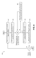
- FIG. 5 illustrates another embodiment of an RF receiver system that may be able to achieve high dynamic range.
- a radio frequency (RF) receiver system that is configured to achieve high dynamic range.
- the RF receiver system may include at least one antenna.
- the RF receiver system may also include a plurality of receivers connected to the at least one antenna.
- the plurality of receivers may be configured to provide different gains.
- the RF receiver system may also include an analog-to-digital (A/D) converter subsystem connected to the plurality of receivers.
- the A/D converter subsystem may include a plurality of A/D converters.
- An overall digitization range of the A/D converter subsystem may be greater than a digitization range of any of the plurality of A/D converters individually.
- the overall digitization range of the A/D converter subsystem may be sufficiently large so as to accommodate a desired overall dynamic range of the RF receiver system.
- the plurality of receivers may also be configured to provide different noise figures and different linearities in addition to different gains.
- the different gains of the plurality of receivers may be selected so that any signal that is within the desired dynamic range of the RF receiver system is detected by and within a linear (instantaneous) range of at least one of the plurality of receivers.
- the digitization ranges of the plurality of A/D converters may overlap.
- the overlap of the digitization ranges may be sufficient to completely contain a desired instantaneous dynamic range of the RF receiver system.
- the desired instantaneous dynamic range may correspond to a minimum desired signal-to-noise ratio for demodulating a received signal.
- the RF receiver system may be configured so that it does not implement automatic gain control.
- the RF receiver system may include an equal number of receivers and A/D converters. Each of the plurality of receivers may have one of the plurality of A/D converters connected thereto.
- the RF receiver system may include M receivers.
- the value of M may depend on a desired overall and instantaneous dynamic range of the RF receiver system.
- Each of the plurality of A/D converters may have a digitization range that may achieve the desired instantaneous dynamic range but that may not achieve the desired overall dynamic range of the RF receiver system.
- Each of the plurality of A/D converters may achieve a sample rate that corresponds to a radio bandwidth.
- Each of the plurality of A/D converters may have the same digitization range. Alternatively, the plurality of A/D converters may have different digitization ranges.
- the plurality of receivers may include a highest gain receiver whose gain corresponds to a lower level of the desired dynamic range of the RF receiver system.
- the plurality of receivers may also include a lowest gain receiver whose gain corresponds to an upper level of the desired dynamic range of the RF receiver system.
- the plurality of receivers may also include at least one intermediate gain receiver whose gain is less than the gain provided by the highest gain receiver and is greater than the gain provided by the lowest gain receiver.
- the RF receiver system may also include a selection component that is connected to the A/D converter subsystem.
- the selection component may select an output signal from one of the plurality of A/D converters for additional processing.
- the selection component may be configured to select a highest gain receiver A/D converter to be a currently selected A/D converter and determine whether the currently selected A/D converter is saturated or near saturation. If it is determined that the currently selected A/D converter is saturated or near saturation, the selection component may select a next lowest gain receiver A/D converter as the currently selected A/D converter and re-determine whether the currently selected A/D converter is saturated or near saturation. If it is determined that the currently selected A/D converter is not saturated or near saturation, the selection component may select the output signal from the currently selected A/D converter for additional processing.
- the selection component may be configured to select a lowest gain receiver A/D converter to be a currently selected A/D converter and to determine whether the currently selected A/D converter is saturated or near saturation. If it is determined that the currently selected A/D converter is not saturated or near saturation, the selection component may select a next highest gain receiver A/D converter as the currently selected A/D converter and re-determine whether the currently selected A/D converter is saturated or near saturation. If it is determined that the currently selected A/D converter is saturated or near saturation, the selection component may be configured to select a next lowest gain receiver A/D converter as the currently selected A/D converter and then select the output signal from the currently selected A/D converter for additional processing.
- a radio frequency (RF) receiver system that is configured to achieve high dynamic range is also disclosed.
- the RF receiver system may include means for receiving RF signals that are within a desired dynamic range of the RF receiver system.
- the RF receiver system may also include means for converting any received signal that is within the desired dynamic range of the RF receiver system from an analog representation into a digital representation.
- the RF receiver system may be configured so that it does not implement automatic gain control.
- the RF receiver system may be configured so that it does not comprise an analog-to-digital (A/D) converter that has a digitization range that is able to accommodate the desired instantaneous dynamic range of the RF receiver system at a sample rate at which the RF receiver system is configured to operate.
- A/D analog-to-digital
- an embodiment means “one or more (but not necessarily all) embodiments,” unless expressly specified otherwise.
- determining (and grammatical variants thereof) is used in an extremely broad sense.
- the term “determining” encompasses a wide variety of actions and, therefore, “determining” can include calculating, computing, processing, deriving, investigating, looking up (e.g., looking up in a table, a database or another data structure), ascertaining and the like. Also, “determining” can include receiving (e.g., receiving information), accessing (e.g., accessing data in a memory) and the like. Also, “determining” can include resolving, selecting, choosing, establishing and the like.
- the present disclosure relates to the dynamic range of an RF receiver, which is a measure of the highest- and lowest-level signals that can be accommodated by the receiver.
- dynamic range of an RF receiver is a measure of the highest- and lowest-level signals that can be accommodated by the receiver.
- the output of an RF receiver may be provided to an analog-to-digital (A/D) converter, which is an electronic circuit that converts an input analog signal to a digital signal.
- A/D analog-to-digital
- the dynamic range that may be achieved by known A/D converters is not as great as the dynamic range that may be achieved by known RF receivers. This is particularly the case where the A/D converter is operating at a high sample rate (e.g., at least 20 MHz).
- RF receiver systems may include some mechanism for addressing the disparity between the relatively high dynamic range of an RF receiver (overall dynamic range) and the relatively low dynamic range of an A/D converter.
- AGC subsystem refers to any subsystem that changes the gain of a variable gain element based on a power detector output.
- An AGC system adjusts the level of the signal output by the RF receiver to be within the dynamic range of the A/D converter. Having an AGC subsystem that operates in this manner may be satisfactory for a number of applications. However, adjusting gain takes time, and for some applications the amount of time that is spent adjusting gain may be quite costly in terms of overall system performance.
- FIG. 1 illustrates an embodiment of an RF receiver system 100 that may be able to achieve high dynamic range without the use of an AGC subsystem.
- the RF receiver system 100 includes multiple RF receivers 102 .
- a first RF receiver 102 a , a second RF receiver 102 b , a third receiver 102 c , and an M th receiver 102 m are shown in FIG. 1 .
- Each of the RF receivers 102 is connected to an antenna 104 .
- the different RF receivers 102 in the system 100 may be configured to achieve different amounts of gain.
- the different RF receivers 102 may also differ with respect to other parameters, such as noise figure and linearity.
- a high gain receiver typically has a better noise figure and worse linearity with large signals than a low gain receiver.
- the term “noise figure” refers to a measure of the degradation of the signal, caused by components in the receiver.
- a lower gain receiver typically has better linearity but a worse noise figure with large signals than a high gain receiver.
- the gains provided by the various receivers 102 may be selected so as to implement a desired dynamic range for the RF receiver system 100 . Stated another way, the gains of the receivers 102 may be selected so that any input signal that is within a desired dynamic range of the RF receiver system 100 may be detected by and within a linear (instantaneous) range of at least one of the RF receivers 102 .
- the first receiver 102 a may be configured to achieve an amount of gain that corresponds to the lower level of the desired dynamic range for the RF receiver system 100 .
- the first receiver 102 a may sometimes be referred to herein as the highest gain and lowest noise figure receiver 102 a in the system 100 , optimized to receive the smallest signals arriving at the antenna 104 .
- the M th receiver 102 m in the system 100 may be configured to achieve an amount of gain that corresponds to the upper level of the desired dynamic range for the RF receiver system 100 .
- the M th receiver 102 m may sometimes be referred to herein as the lowest gain and highest linearity receiver 102 m in the system 100 , optimized to receive the largest signals arriving at the antenna.
- the second and third receivers 102 b , 102 c may be configured to achieve an amount of gain that is less than the gain achieved by the highest gain receiver 102 a , but that is greater than the gain achieved by the lowest gain receiver 102 m .
- the second and third receivers 102 b , 102 c may sometimes be referred to herein as intermediate gain receivers 102 b , 102 c.
- the RF receiver system 100 may also include an A/D converter subsystem 106 that includes multiple A/D converters 108 .
- the RF receiver system 100 may be configured so that for each receiver 102 in the system 100 , a separate A/D converter 108 is provided.
- the RF receiver system 100 may include an equal number of receivers 102 and A/D converters 108 .
- a first A/D converter 108 a , a second A/D converter 108 b , a third A/D converter 108 c , and an M th A/D converter 108 m are shown in FIG. 1 .
- the A/D converters 108 may be connected to the receivers 102 so that each of the receivers 102 has one of the A/D converters 108 connected thereto.
- the first A/D converter 108 a may be connected to the first receiver 102 a
- the second A/D converter 108 b may be connected to the second receiver 102 b
- the third A/D converter 108 c may be connected to the third receiver 102 c
- the M th A/D converter 108 d may be connected to the M th receiver 102 m.
- Each A/D converter 108 in the RF receiver system 100 may be configured to achieve a sample rate that corresponds to a radio bandwidth, i.e., that adequately digitizes the signals received by the RF receiver system 100 .
- the sample rate may be at least 20 MHz to be high enough to digitize a typical radio band of tens of MHz.
- the digitization range of each A/D converter 108 may be less than the desired dynamic range of the RF receiver system 100 .
- the “digitization range” of an A/D converter 108 may be a measure of the number of discrete values that it can produce over a given range of input values.
- the digitization range of an A/D converter 108 may sometimes be referred to as the dynamic range of the A/D converter 108 .
- the different receivers 102 in the system 100 may be configured to provide different amounts of gain.
- the overall digitization range of the A/D converter subsystem 106 i.e., the digitization range of the A/D converter subsystem 106 as a whole
- the overall digitization range of the A/D converter subsystem 106 may be at least as great as the desired dynamic range of the RF receiver system 100 .
- the RF receiver system 100 that is shown in FIG. 1 does not include an automatic gain control subsystem.
- the depicted RF receiver system 100 may be able to achieve high dynamic range without implementing automatic gain control.
- the RF receiver system 100 may also include a selection component 110 .
- the selection component 110 is connected to the A/D converters 108 .
- the selection component 110 selects an output signal from one of the A/D converters 108 for additional processing. The operation of the selection component 110 will be described in greater detail below.
- FIG. 2 illustrates an example showing how the RF receiver system 100 of FIG. 1 may be configured so that the overall digitization range 212 of the A/D converter subsystem 106 is at least as great as the desired dynamic range of the RF receiver system 100 .
- exemplary digitization ranges 214 of each of the A/D converters 108 in the RF receiver system 100 are also shown in FIG. 2 .
- FIG. 2 illustrates an example showing how the RF receiver system 100 of FIG. 1 may be configured so that the overall digitization range 212 of the A/D converter subsystem 106 is at least as great as the desired dynamic range of the RF receiver
- FIG. 2 shows an exemplary digitization range 214 a of the first A/D converter 108 a , an exemplary digitization range 214 b of the second A/D converter 108 b , an exemplary digitization range 214 c of the third A/D converter 108 c , and an exemplary digitization range 214 m of the M th A/D converter 108 m.
- the first A/D converter 108 a may be connected to the first receiver 102 a , which has the highest gain of the receivers 102 in the system 100 .
- the digitization range 214 a of the first A/D converter 108 a corresponds to the least significant bits of the overall digitization range 212 of the A/D converter subsystem 106 .
- the M th A/D converter 108 m may be connected to the M th receiver 102 m , which has the lowest gain of the receivers 102 in the system 100 .
- the digitization range 214 m of the M th A/D converter 108 m corresponds to the most significant bits of the overall digitization range 212 of the A/D converter subsystem 106 .
- each A/D converter 108 in the RF receiver system 100 provides a digitization range of 10 bits while achieving a high sample rate (e.g., at least 20 MHz).
- the RF receiver system 100 may be configured so that the digitization ranges 214 of the different A/D converters 108 overlap. This is shown in FIG. 2 .
- the digitization ranges 214 of the A/D converters 108 overlap by six bits. This may be accomplished by selecting the gains of the different receivers 102 so that if the first receiver 102 a provides a gain of 100 dB, the second receiver 102 b provides a gain of 76 dB, the third receiver 102 c provides a gain of 52 dB, and the M th receiver 102 m provides a gain of 28 dB.
- the configuration that is shown in FIG. 2 is exemplary only.
- the digitization ranges 214 of the A/D converters 108 may overlap by more than six bits, or by fewer than six bits.
- the extent to which the digitization ranges 214 of the different A/D converters 108 overlap may depend on a factor that will be referred to herein as the “desired instantaneous dynamic range” of the system 100 .
- the desired instantaneous dynamic range of the RF receiver system 100 may be related to the desired performance of the RF receiver system 100 .
- the desired instantaneous dynamic range may correspond to the minimum desired signal-to-noise ratio for demodulating a received signal.
- the desired instantaneous dynamic range may also reflect the reality that it typically is not possible to simultaneously use bits from the outputs of different A/D converters 108 , because of non-linearities associated with the differences in gain between the different receivers 102 .
- the selection component 110 in the RF receiver system 100 may be configured to select an output signal from exactly one of the A/D converters 108 for further processing, rather than trying to combine different bits from different output signals.
- the RF receiver system 100 may be configured so that the digitization ranges 214 of the A/D converters 108 overlap to an extent that is sufficient to completely contain the desired instantaneous dynamic range of the RF receiver system 100 .
- the desired instantaneous dynamic range of the RF receiver system 100 is around 12 dB, which corresponds to approximately two bits, then the system 100 may be designed so that the digitization ranges 214 of the A/D converters 108 overlap by at least two or three bits.
- the receiver A/D converters 108 may be configured to be “phase aligned”. The outputs from each receiver A/D converter need to produce approximately the same phase for a given input signal. This may be accomplished using delay-line techniques or by using a FIFO (First In, First Out) queue on the A/D samples to select the correct sample that is time-aligned with the samples from the other receiver A/D converters 108 .
- FIFO First In, First Out
- the desired instantaneous dynamic range for the RF receiver system 100 may depend on how the RF receiver system 100 is being used. For example, if the RF receiver system 100 is being used in a mobile phone where the level of performance is not extremely high, the desired instantaneous dynamic range may be around 12 dB, which corresponds to around two or three bits. As indicated above, in this case the RF receiver system 100 may be configured so that the digitization ranges 214 of the A/D converters 108 overlap by at least two or three bits. However, if the RF receiver system 100 is being used in a video system where a much higher level of performance is desired, the desired instantaneous dynamic range may be around 40 dB, which corresponds to around five or six bits. In this case, the RF receiver system 100 may be configured so that the digitization ranges 214 of the A/D converters 108 overlap by at least five or six bits.
- each of the A/D converters 108 in the RF receiver system 100 has the same digitization range 214 (i.e., 10 bits).
- the RF receiver system 100 may be configured so that different A/D converters 108 have different digitization ranges.
- the number of receivers 102 that are utilized in the RF receiver system 100 may depend on the desired instantaneous dynamic range of the RF receiver system 100 .
- four receivers 102 are utilized to achieve an overall digitization range of 22 bits (which, as indicated above, corresponds to a dynamic range of around 130 dB) where each A/D converter has a digitization range of 10 bits and the desired instantaneous dynamic range is 6 bits.
- the desired instantaneous dynamic range of the RF receiver system 100 were less than 6 bits, it may be possible for fewer than 4 receivers 102 to be utilized to achieve an overall digitization range 212 of (at least) 22 bits.
- the desired instantaneous dynamic range of the RF receiver system 100 were greater than 6 bits, more than 4 receivers 102 may be utilized to achieve an overall digitization range 212 of 22 bits.
- the selection component 110 selects an output signal from one of the A/D converters 108 for additional processing.
- FIG. 3 illustrates an exemplary method 300 for determining which of the output signals is selected. The method 300 may be implemented by the selection component 110 .
- the phrase “highest gain A/D converter” may refer to the A/D converter 108 that is connected to the receiver 102 having the highest gain relative to the other receivers 102 in the RF receiver system 100 .
- the first A/D converter 108 a may be the highest gain A/D converter 108 a.
- the phrase “currently selected A/D converter” may refer to the A/D converter 108 whose output is currently selected for processing by the selection component 110 .
- the phrase “next lowest gain A/D converter” may refer to the A/D converter 108 that is connected to the receiver 102 having the next lowest gain relative to the receiver 102 that is connected to the currently selected A/D converter 108 . For instance, referring again to the example that is shown in FIG. 2 , if the first A/D converter 108 a is the currently selected A/D converter 108 , then the second A/D converter 108 b may be the next lowest gain A/D converter 108 b.
- the depicted method 300 may be implemented as a signal is being received and processed by the RF receiver system 100 .
- the highest gain A/D converter 108 may be selected 304 to be the currently selected A/D converter 108 .
- the method 300 may then involve determining 312 whether an additional sample is available for processing. If so, the method 300 may return to step 302 and proceed as described above. If not, the method 300 may end.
- FIG. 4 illustrates another exemplary method 400 for determining which of the output signals of the A/D converters 108 is selected. As before, the method 400 may be implemented by the selection component 110 .
- the phrase “lowest gain A/D converter” may refer to the A/D converter 108 that is connected to the receiver 102 having the lowest gain relative to the other receivers 102 in the RF receiver system 100 .
- the M th A/D converter 108 m may be the lowest gain A/D converter 108 m.
- next highest gain A/D converter may refer to the A/D converter 108 that is connected to the receiver 102 having the next highest gain relative to the receiver 102 that is connected to the currently selected A/D converter 108 .
- the third A/D converter 108 c may be the next highest gain A/D converter 108 c.
- the phrase “currently selected A/D converter” may refer to the A/D converter 108 whose output is currently selected for processing by the selection component 110 .
- the phrase “next lowest gain A/D converter” may refer to the A/D converter 108 that is connected to the receiver 102 having the next lowest gain relative to the receiver 102 that is connected to the currently selected A/D converter 108 .
- the method 400 shown in FIG. 4 may be implemented as a signal is being received and processed by the RF receiver system 100 .
- the lowest gain A/D converter 108 may be selected 404 to be the currently selected A/D converter 108 .
- the next lowest gain A/D converter 108 may be selected 410 as the currently selected A/D converter 108 , and the output signal from the currently selected A/D converter 108 may be selected 412 for additional processing.
- the method 400 may then involve determining 402 whether an additional sample is available for processing from the A/D converters 108 . If so, the method 400 may return to step 402 and proceed as described above. If not, the method 400 may end.
- the methods 300 , 400 shown in FIGS. 3 and 4 for determining which of the output signals of the A/D converters 108 is selected are exemplary only. Other methods may be used.
- the selection component 110 may a-priori know which receiver 102 and A/D converter 108 to use and select it directly based on comparing the outputs from the A/D converters 108 and using an output from an A/D converter 108 that is known to be within the digitization range (dynamic range) of the A/D converter 108 . Under some circumstances, multiple outputs from multiple A/D converters 108 may be used.
- the selection component 110 may be configured so that it only selects a different A/D converter 108 if the signal is not within the digitization range (dynamic range) of the A/D converter 108 within a defined tolerance. This may be done instead of, or possibly in addition to, checking for saturation of the A/D converter 108 .
- FIG. 5 illustrates another embodiment of an RF receiver system 500 that is able to achieve high dynamic gain without the use of an AGC subsystem.
- each receiver 102 is connected to the same antenna 104 .
- each receiver 502 is connected to a different antenna 504 .
- a first antenna 504 a is connected to the first receiver 502 a
- a second antenna 504 b is connected to the second receiver 502 b
- a third antenna 504 c is connected to the third receiver 504 c
- an M th antenna 504 m is connected to the M th receiver 502 m.
- the RF receiver systems 100 , 500 described herein may be used in a wide variety of systems. Some exemplary systems in which these RF receiver systems 100 , 500 may be used are described in U.S. patent application Ser. No. 11/140,081, titled “Burst Spread Spectrum Radio System and Method for Asset Tracking and Data Telemetry,” filed May 27, 2005, with inventors Sy Prestwich, Scott Bevan, Dirk Ostermiller, and K. Deric Eldredge (hereinafter, “the '181 application”). The '181 application is assigned to the assignee of the present application, and is hereby incorporated by reference in its entirety.
- Information and signals may be represented using any of a variety of different technologies and techniques.
- data, instructions, commands, information, signals and the like that may be referenced throughout the above description may be represented by voltages, currents, electromagnetic waves, magnetic fields or particles, optical fields or particles or any combination thereof.
- DSP digital signal processor
- ASIC application specific integrated circuit
- FPGA field programmable gate array signal
- a general purpose processor may be a microprocessor, but in the alternative, the processor may be any conventional processor, controller, microcontroller or state machine.
- a processor may also be implemented as a combination of computing devices, e.g., a combination of a DSP and a microprocessor, a plurality of microprocessors, one or more microprocessors in conjunction with a DSP core or any other such configuration.
- a software module may reside in any form of storage medium that is known in the art. Some examples of storage media that may be used include RAM memory, flash memory, ROM memory, EPROM memory, EEPROM memory, registers, a hard disk, a removable disk, a CD-ROM and so forth.
- a software module may comprise a single instruction, or many instructions, and may be distributed over several different code segments, among different programs and across multiple storage media.
- An exemplary storage medium may be coupled to a processor such that the processor can read information from, and write information to, the storage medium. In the alternative, the storage medium may be integral to the processor.
- the methods disclosed herein comprise one or more steps or actions for achieving the described method.
- the method steps and/or actions may be interchanged with one another without departing from the scope of the claims.
- the order and/or use of specific steps and/or actions may be modified without departing from the scope of the claims.
Landscapes
- Engineering & Computer Science (AREA)
- Computer Networks & Wireless Communication (AREA)
- Signal Processing (AREA)
- Circuits Of Receivers In General (AREA)
Abstract
Description
Claims (21)
Priority Applications (1)
| Application Number | Priority Date | Filing Date | Title |
|---|---|---|---|
| US12/046,239 US8068799B1 (en) | 2008-03-11 | 2008-03-11 | Radio frequency receiver systems that are configured to achieve high dynamic range |
Applications Claiming Priority (1)
| Application Number | Priority Date | Filing Date | Title |
|---|---|---|---|
| US12/046,239 US8068799B1 (en) | 2008-03-11 | 2008-03-11 | Radio frequency receiver systems that are configured to achieve high dynamic range |
Publications (1)
| Publication Number | Publication Date |
|---|---|
| US8068799B1 true US8068799B1 (en) | 2011-11-29 |
Family
ID=44994381
Family Applications (1)
| Application Number | Title | Priority Date | Filing Date |
|---|---|---|---|
| US12/046,239 Expired - Fee Related US8068799B1 (en) | 2008-03-11 | 2008-03-11 | Radio frequency receiver systems that are configured to achieve high dynamic range |
Country Status (1)
| Country | Link |
|---|---|
| US (1) | US8068799B1 (en) |
Cited By (5)
| Publication number | Priority date | Publication date | Assignee | Title |
|---|---|---|---|---|
| CN103259547A (en) * | 2013-03-27 | 2013-08-21 | 安徽海聚信息科技有限责任公司 | Receiving device based on Zigbee technology |
| US9413578B2 (en) * | 2013-02-19 | 2016-08-09 | Broadcom Corporation | Receiver with reduced wake-up time |
| US9654134B2 (en) | 2015-02-16 | 2017-05-16 | Sound Devices Llc | High dynamic range analog-to-digital conversion with selective regression based data repair |
| US10742246B2 (en) | 2016-12-22 | 2020-08-11 | Nxp B.V. | Receiver path arrangement |
| US11064446B2 (en) | 2016-04-26 | 2021-07-13 | Anatog Devices, Inc. | Apparatus and methods for wideband receivers |
Citations (13)
| Publication number | Priority date | Publication date | Assignee | Title |
|---|---|---|---|---|
| US4652882A (en) * | 1982-09-30 | 1987-03-24 | Raytheon Company | Receiver with wide dynamic range |
| US6031478A (en) * | 1998-02-19 | 2000-02-29 | Nortel Networks Corporation | Dynamic range extension of wideband receiver |
| US6289048B1 (en) | 2000-01-06 | 2001-09-11 | Cubic Communications, Inc. | Apparatus and method for improving dynamic range in a receiver |
| US6321073B1 (en) * | 2000-01-31 | 2001-11-20 | Motorola, Inc. | Radiotelephone receiver and method with improved dynamic range and DC offset correction |
| US6445732B1 (en) * | 1998-09-23 | 2002-09-03 | Conexant Systems, Inc. | Dynamic range reduction circuitry for a digital communications receiver |
| US20030222206A1 (en) | 2002-06-04 | 2003-12-04 | Azary Zoltan D. | High dynamic range receiver |
| US6670901B2 (en) * | 2001-07-31 | 2003-12-30 | Motorola, Inc. | Dynamic range on demand receiver and method of varying same |
| US6862323B1 (en) * | 2001-08-08 | 2005-03-01 | Rockwell Collins | Low pass filters for high dynamic range wideband direct conversion receiver |
| US7062001B2 (en) * | 2001-08-31 | 2006-06-13 | Her Majesty The Queen In Right Of Canada, As Represented By The Minister Of National Defence Of Her Majesty's Canadian Government | Adaptive multi-channel, multi-function |
| US7262724B2 (en) * | 2005-03-31 | 2007-08-28 | Freescale Semiconductor, Inc. | System and method for adjusting dynamic range of analog-to-digital converter |
| US7283797B1 (en) * | 1998-03-06 | 2007-10-16 | Ericsson Inc. | System and method of improving the dynamic range of a receiver in the presence of a narrowband interfering signal |
| US7440525B2 (en) * | 2004-08-27 | 2008-10-21 | Mindspeed Technologies, Inc. | Dynamic range signal to noise optimization system and method for receiver |
| US7672359B2 (en) * | 2004-01-28 | 2010-03-02 | Andrew Llc | Spread-spectrum receivers with extended dynamic range |
-
2008
- 2008-03-11 US US12/046,239 patent/US8068799B1/en not_active Expired - Fee Related
Patent Citations (14)
| Publication number | Priority date | Publication date | Assignee | Title |
|---|---|---|---|---|
| US4652882A (en) * | 1982-09-30 | 1987-03-24 | Raytheon Company | Receiver with wide dynamic range |
| US6031478A (en) * | 1998-02-19 | 2000-02-29 | Nortel Networks Corporation | Dynamic range extension of wideband receiver |
| US7283797B1 (en) * | 1998-03-06 | 2007-10-16 | Ericsson Inc. | System and method of improving the dynamic range of a receiver in the presence of a narrowband interfering signal |
| US6445732B1 (en) * | 1998-09-23 | 2002-09-03 | Conexant Systems, Inc. | Dynamic range reduction circuitry for a digital communications receiver |
| US6289048B1 (en) | 2000-01-06 | 2001-09-11 | Cubic Communications, Inc. | Apparatus and method for improving dynamic range in a receiver |
| US6321073B1 (en) * | 2000-01-31 | 2001-11-20 | Motorola, Inc. | Radiotelephone receiver and method with improved dynamic range and DC offset correction |
| US6670901B2 (en) * | 2001-07-31 | 2003-12-30 | Motorola, Inc. | Dynamic range on demand receiver and method of varying same |
| US6862323B1 (en) * | 2001-08-08 | 2005-03-01 | Rockwell Collins | Low pass filters for high dynamic range wideband direct conversion receiver |
| US7062001B2 (en) * | 2001-08-31 | 2006-06-13 | Her Majesty The Queen In Right Of Canada, As Represented By The Minister Of National Defence Of Her Majesty's Canadian Government | Adaptive multi-channel, multi-function |
| US6707025B2 (en) | 2002-06-04 | 2004-03-16 | Agilent Technologies, Inc. | High dynamic range receiver |
| US20030222206A1 (en) | 2002-06-04 | 2003-12-04 | Azary Zoltan D. | High dynamic range receiver |
| US7672359B2 (en) * | 2004-01-28 | 2010-03-02 | Andrew Llc | Spread-spectrum receivers with extended dynamic range |
| US7440525B2 (en) * | 2004-08-27 | 2008-10-21 | Mindspeed Technologies, Inc. | Dynamic range signal to noise optimization system and method for receiver |
| US7262724B2 (en) * | 2005-03-31 | 2007-08-28 | Freescale Semiconductor, Inc. | System and method for adjusting dynamic range of analog-to-digital converter |
Cited By (5)
| Publication number | Priority date | Publication date | Assignee | Title |
|---|---|---|---|---|
| US9413578B2 (en) * | 2013-02-19 | 2016-08-09 | Broadcom Corporation | Receiver with reduced wake-up time |
| CN103259547A (en) * | 2013-03-27 | 2013-08-21 | 安徽海聚信息科技有限责任公司 | Receiving device based on Zigbee technology |
| US9654134B2 (en) | 2015-02-16 | 2017-05-16 | Sound Devices Llc | High dynamic range analog-to-digital conversion with selective regression based data repair |
| US11064446B2 (en) | 2016-04-26 | 2021-07-13 | Anatog Devices, Inc. | Apparatus and methods for wideband receivers |
| US10742246B2 (en) | 2016-12-22 | 2020-08-11 | Nxp B.V. | Receiver path arrangement |
Similar Documents
| Publication | Publication Date | Title |
|---|---|---|
| US8068799B1 (en) | Radio frequency receiver systems that are configured to achieve high dynamic range | |
| US6993291B2 (en) | Method and apparatus for continuously controlling the dynamic range from an analog-to-digital converter | |
| US20110150053A1 (en) | Method of detecting a radar signal, radar detection module, and wireless transceiver including the same | |
| WO2004082135A2 (en) | Closed loop power control of non-constant envelope waveforms using sample/hold | |
| US10389482B2 (en) | Radio-frequency apparatus with improved power consumption and associated methods | |
| US9831902B2 (en) | Bluetooth smart signal receiving method and device using improved automatic gain control | |
| CN110291729B (en) | MIMO array calibration method based on opportunistic signals | |
| US6922450B2 (en) | Direction of arrival estimator and direction of arrival estimation method | |
| US7697614B2 (en) | System and method for calibrating an analog signal path during operation in an ultra wideband receiver | |
| US20030081706A1 (en) | Noise reduction filtering in a wireless communication system | |
| US7012981B2 (en) | Method and apparatus for improving data frame synchronization in a low SNR environment | |
| US20050089123A1 (en) | Circuit method and system for automatic gain control | |
| CN101340198B (en) | Calibration method, apparatus and system for RF receiver | |
| EP3226447A1 (en) | Method and system for generating a received signal strength indicator (rssi) value from a radio frequency (rf) signal | |
| US8340218B2 (en) | Integrated micro-sampling wireless receiver | |
| JPH10215176A (en) | A/d conversion unit | |
| US11005491B1 (en) | System and method for wireless receiver communication based on variable leading bit orthogonal code sets | |
| US20030006839A1 (en) | Extended range power detector and amplifier and method | |
| US7733252B2 (en) | Method and apparatus for delay and combining circuitry | |
| US9473186B2 (en) | Method of controlling receiver gain automatically and apparatus for automatic gain control in receiver | |
| US20180159706A1 (en) | Radio-Frequency Apparatus with Digital Signal Arrival Detection and Associated Methods | |
| US20020017949A1 (en) | Apparatus and method for determining a pulse position for a signal encoded by a pulse modulation | |
| CN103795427A (en) | Anti-jamming method and anti-jamming device for wireless communication system | |
| KR101924906B1 (en) | Appratus and method for controlling gain | |
| US8223889B2 (en) | Opportunistic radio frequency communications |
Legal Events
| Date | Code | Title | Description |
|---|---|---|---|
| AS | Assignment |
Owner name: S5 WIRELESS, INC., UTAH Free format text: ASSIGNMENT OF ASSIGNORS INTEREST;ASSIGNORS:PRESTWICH, SY;BEVAN, SCOTT;REEL/FRAME:020649/0153 Effective date: 20080226 |
|
| AS | Assignment |
Owner name: EAGLE RIVER HOLDINGS, LLC (A WASHINGTON LLC), AS A Free format text: SECURITY AGREEMENT;ASSIGNOR:S5 WIRELESS, INC. (A DELAWARE CORPORATION);REEL/FRAME:021029/0759 Effective date: 20080523 |
|
| AS | Assignment |
Owner name: EAGLE RIVER HOLDINGS, LLC, AS AGENT FOR ITSELF AND Free format text: SECURITY AGREEMENT;ASSIGNOR:S5 WIRELESS, INC.;REEL/FRAME:021423/0820 Effective date: 20080813 |
|
| AS | Assignment |
Owner name: EAGLE RIVER HOLDINGS, LLC, AS AGENT FOR ITSELF AND Free format text: SECURITY AGREEMENT;ASSIGNOR:S5 WIRELESS, INC.;REEL/FRAME:022320/0370 Effective date: 20090129 |
|
| AS | Assignment |
Owner name: S5 WIRELESS, INC., UTAH Free format text: NOTICE OF RELEASE OF SECURITY INTEREST;ASSIGNOR:EAGLE RIVER HOLDINGS, LLC;REEL/FRAME:024555/0862 Effective date: 20100614 Owner name: RECON DYNAMICS, LLC, WASHINGTON Free format text: NUNC PRO TUNC ASSIGNMENT;ASSIGNOR:S5 WIRELESS, INC.;REEL/FRAME:024555/0870 Effective date: 20100527 |
|
| REMI | Maintenance fee reminder mailed | ||
| LAPS | Lapse for failure to pay maintenance fees | ||
| STCH | Information on status: patent discontinuation |
Free format text: PATENT EXPIRED DUE TO NONPAYMENT OF MAINTENANCE FEES UNDER 37 CFR 1.362 |
|
| FP | Expired due to failure to pay maintenance fee |
Effective date: 20151129 |