US8068730B2 - Wavelength division multiplex signal monitoring system and wavelength division multiplex transmission device equipped with the same - Google Patents
Wavelength division multiplex signal monitoring system and wavelength division multiplex transmission device equipped with the same Download PDFInfo
- Publication number
- US8068730B2 US8068730B2 US12/219,862 US21986208A US8068730B2 US 8068730 B2 US8068730 B2 US 8068730B2 US 21986208 A US21986208 A US 21986208A US 8068730 B2 US8068730 B2 US 8068730B2
- Authority
- US
- United States
- Prior art keywords
- division multiplex
- wavelength division
- multiplex signal
- channel
- waveform
- Prior art date
- Legal status (The legal status is an assumption and is not a legal conclusion. Google has not performed a legal analysis and makes no representation as to the accuracy of the status listed.)
- Expired - Fee Related, expires
Links
Images


Classifications
-
- H—ELECTRICITY
- H04—ELECTRIC COMMUNICATION TECHNIQUE
- H04B—TRANSMISSION
- H04B10/00—Transmission systems employing electromagnetic waves other than radio-waves, e.g. infrared, visible or ultraviolet light, or employing corpuscular radiation, e.g. quantum communication
- H04B10/07—Arrangements for monitoring or testing transmission systems; Arrangements for fault measurement of transmission systems
- H04B10/075—Arrangements for monitoring or testing transmission systems; Arrangements for fault measurement of transmission systems using an in-service signal
- H04B10/079—Arrangements for monitoring or testing transmission systems; Arrangements for fault measurement of transmission systems using an in-service signal using measurements of the data signal
- H04B10/0795—Performance monitoring; Measurement of transmission parameters
- H04B10/07955—Monitoring or measuring power
-
- H—ELECTRICITY
- H04—ELECTRIC COMMUNICATION TECHNIQUE
- H04J—MULTIPLEX COMMUNICATION
- H04J14/00—Optical multiplex systems
- H04J14/02—Wavelength-division multiplex systems
- H04J14/0221—Power control, e.g. to keep the total optical power constant
- H04J14/02216—Power control, e.g. to keep the total optical power constant by gain equalization
Definitions
- the present invention relates to a WDM signal monitoring system that monitors a power level and a wavelength of each channel of a wavelength division multiplexed (WDM) signal, that is, a so-called optical channel monitor (OCM), and a WDM transmission device equipped with the WDM signal monitoring system.
- WDM wavelength division multiplexed
- OCM optical channel monitor
- the WDM transmission device measures a power level and a wavelength of a Wavelength Division Multiplex (WDM) signal by Optical Channel Monitor (OCM).
- OCM Optical Channel Monitor
- Examples of construction of the OCM are shown in FIGS. 1 and 2 .
- An example in FIG. 1 demultiplexes a WDM signal by an Arrayed Waveguide Grating (AWG) divider 10 , and receives it with a photodiode (PD) array 12 .
- AMG Arrayed Waveguide Grating
- PD photodiode
- FIG. 2 spatially performs dispersion using a diffraction grating 14 , and receives it with a PD array 16 .
- the example of FIG. 1 in order to reduce cost, it is desirable to reduce the number of PDs.
- four PDs per each channel are used as shown in an enlarged view on a right-hand side in FIG. 1 .
- the example finds a spectrum waveform by performing approximate calculation, such as Gaussian approximation, on the basis of a received light level of each PD, and determines the power level and wavelength of the signal.
- This approximation procedure is shown in FIG. 3 .
- black dots 18 denote measured values from four PDs, and a curve 20 shows an approximated curve.
- the power level P and wavelength ⁇ of the channel are determined.
- waveforms of 10-Gbps signal and 40-Gbps signal at the time of adopting a Non Return to Zero (NRZ) modulation system are shown in FIGS. 4 and 5 , respectively.
- NRZ Non Return to Zero
- Various embodiments of the present invention provide a WDM signal monitoring system that includes a measuring unit that measures a power level of each of a plurality of predetermined wavelength bands in a wavelength division multiplex signal, a waveform determination unit that determines an approximate waveform of each of a plurality of channels that form the wavelength division multiplex signal based on bit rate information and modulation system information of each of the plurality of channels, and an approximation unit that determines a power level and a wavelength of each channel by approximating the power level measured in each of the plurality of predetermined wavelength bands with the approximate waveform determined for each of the plurality of channels.
- a wavelength division multiplex signal monitoring system including a divider that demultiplexes an input side wavelength division multiplex signal into a plurality of channels, an add-drop processor unit that performs add and drop processing on each channel demultiplexed by the divider, a plurality of optical variable attenuators that control a power level of an optical signal of each channel after add-drop processing, a synthesizer that multiplexes an optical signal after power level control, and generates an output side wavelength division multiplex signal, a measuring unit that measures a power of each of a plurality of predetermined wavelength bands in the output side wavelength division multiplex signal, a waveform determination unit that determines an approximate waveform of each of a plurality of channels that form the output side wavelength division multiplex signal based on bit rate information and modulation system information of each of the plurality of channels, an approximation unit that determines a power level and a wavelength of each channel, which the waveform determination unit determined, by approximating the power level measured in each
- FIG. 1 is a diagram showing a first example of a conventional OCM
- FIG. 2 is a diagram showing a second example of the conventional OCM
- FIG. 3 is an explanatory graph about a determination method of a wavelength and a power level in the conventional OCM
- FIG. 4 is a chart showing a waveform of 10-Gbps NRZ
- FIG. 5 is a chart showing a waveform of 40-Gbps NRZ
- FIG. 6 is a chart showing difference among waveforms according to modulation systems
- FIG. 7A is a block diagram showing a first construction of a WDM transmission device according to an embodiment of the present invention.
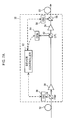
- FIG. 7B is a block diagram showing a second construction of the WDM transmission device according to an embodiment of the present invention.
- FIG. 7C is a block diagram showing a third construction of the WDM transmission device according to an embodiment of the present invention.
- FIG. 7D is a block diagram showing a fourth construction of a WDM transmission device according to an embodiment of the present invention.
- FIG. 8 is a diagram showing a linear connection network according to an embodiment of the present invention.
- FIG. 9 is a diagram showing a ring connection network according to an embodiment of the present invention.
- FIG. 10 is a diagram showing a mesh connection network according to an embodiment of the present invention.
- FIG. 11 is a diagram showing an example of the linear connection network according to an embodiment of the present invention.
- FIG. 12 is a block diagram showing detailed construction of an OCM unit according to an embodiment of the present invention.
- FIG. 13 is a chart showing a first example of waveform data stored in a waveform database according to an embodiment of the present invention.
- FIG. 14 is a chart showing a second example of waveform data stored in the waveform database according to an embodiment of the present invention.
- FIG. 15 is a graph showing measurement data by PDs according to an embodiment of the present invention.
- FIG. 16 is a chart showing an example of approximating measurement data with an approximate waveform determined from the bit rate and modulation system according to an embodiment of the present invention
- FIG. 17 is a graph showing measurement data by PDs according to an embodiment of the present invention.
- FIG. 18 is a chart showing an example of approximating measurement data with an approximate waveform which is determined with further adding route information according to an embodiment of the present invention.
- FIG. 19 is a diagram showing an example of controlling information, including a bit rate etc., by a network management system without using an OSC according to an embodiment of the present invention.
- FIG. 20 is a table showing an example of a database in a device controller of a WDM transmission device according to an embodiment of the present invention.
- FIG. 21 is a table showing an example of a waveform database of the OCM according to an embodiment of the present invention.
- FIG. 22 is a table showing an example of a database in the device controller of the WDM transmission device, including route information according to an embodiment of the present invention
- FIG. 23 is a table showing an example of a waveform database which OCM has and which includes route information according to an embodiment of the present invention.
- FIG. 24 is a table showing an example of a database of a network monitor according to an embodiment of the present invention.
- FIGS. 7A and 7B show examples of construction of a WDM transmission device 30 according to an embodiment of the present invention.
- a distribution Raman amplifier 55 is in a transmission passage 32 , and this distribution Raman amplifier 55 includes a pumping light generator and a pumping light controller.
- a WDM signal is amplified by controlling pumping light strength (pump power) with the pumping light controller.
- An OSC which includes type information on a signal of each channel, including a bit rate, a modulation system, etc., in an Optical Supervisory Channel (OSC) coupler 34 is separated from the signal sent from a preceding stage of the WDM transmission device through the transmission passage 32 , and is sent to an OSC unit 36 .
- Other WDM signals are amplified by optical amplifiers 38 and 54 , and are multiplexed with the OSC from an OSC unit 58 in an OSC coupler 56 to be sent out to a transmission passage 60 .
- OSC Optical Supervisory Channel
- FIGS. 7C and 7D show other examples of construction of the WDM transmission device 30 .
- the distribution Raman amplifier 55 is in the transmission passage 32 and the WDM signal is amplified.
- An OSC which includes the type information on the signal of each channel, including the bit rate, modulation system, etc., in the OSC coupler 34 is separated from the signal sent from a preceding stage of the WDM transmission device through the transmission passage 32 , and is sent to the OSC unit 36 .
- Another WDM signal is amplified by the optical amplifier 38 and is separated into each channel in a divider 40 to be inputted into an add-drop unit 46 , which is constructed of drop optical switches 42 and add optical switches 44 .
- a drop optical switch 42 performs switching of passing through this WDM transmission device or dropping into a low order device (not illustrated), every channel.
- An add optical switch 44 selects an optical signal from the optical switch 42 or optical signal from the low order device (not illustrated), every channel.
- the optical signals which come out of the add-drop unit 46 are multiplexed by a synthesizer 50 after a power level is adjusted every channel by each optical variable attenuator 48 .
- the WDM signal which comes out of the synthesizer 50 is partially split for measurement by an optical coupler 52 , and the residual is amplified by an optical amplifier 54 , and is multiplexed with the OSC, derived from the OSC unit 58 , by an OSC coupler to be sent out to a transmission passage 60 .
- a device controller 62 controls each optical switch in the add-drop unit 46 on the basis of the information from the OSC unit 36 , and controls the OSC unit 58 .
- the device controller 62 sends information, including a channel name, the bit rate, the modulation system, etc., to the following WDM transmission device through the OSC unit 58 through the transmission passage 60 .
- the device controller 62 will be described in full detail later.
- An OCM unit 64 measures a power level and a wavelength in each channel about the WDM signal separated by the optical coupler 52 . Furthermore, on the basis of the result, the OCM unit 64 may perform tilt compensation by controlling the optical variable attenuator 48 or distribution Raman amplifier 55 so that a power level in each channel may become a target level. In addition, the OCM unit 64 passes measurement results of the power level and wavelength in each channel to the optical variable attenuator 48 or distribution Raman amplifier 55 , and may perform tilt compensation by performing control so that the power level in each channel may become the target level in the optical variable attenuator 48 or distribution Raman amplifier 55 . The OCM unit 64 will be described in full detail later.
- a device controller 62 of a WDM transmission device along which the path newly set passes first (is added) generates data of a channel name, a bit rate, and a modulation system about this path to store them in a database. Then, the device controller 62 sends the generated data to the following WDM transmission device using an OSC. In the following WDM transmission device, the sent data is stored in a database and transferred to the next WDM transmission device. This is repeated until the data reaches a WDM transmission device that a path passes at the end (is dropped). Thereby, data of the channel name, bit rate, modulation system, etc.
- the data shown in FIG. 20 is the data in the WDM transmission device 5 in the network where five WDM transmission devices which accommodate 40 wavelengths are connected linearly as shown in FIG. 11 .
- data in a channel 1 is data transmitted from a transmission device 2
- data in a channel 3 is data transmitted from a WDM transmission device 4 .
- the data shown in FIG. 20 is used to determine an approximate waveform of each channel.
- FIG. 12 shows a detailed construction of the OCM unit 64 .
- a divider 66 and a PD array 68 measure each power level of a plurality of predetermined wavelength bands (for example, 4 to 6 wavelengths per each channel).
- a waveform database 70 of all the possible combinations of the bit rate and modulation system.
- a waveform search unit 72 searches the waveform database 70 on the basis of the bit rate information and modulation system information of each channel from the device controller 62 to determine an approximate waveform of each channel.
- a waveform approximation unit 74 approximates the measured values of the power level in a several number of wavelengths per channel which are outputted from the PD array 68 with an approximate waveform determined in the waveform search unit 72 , thereby determining a more precise power level and waveform.
- a controller 76 performs tilt compensation by controlling the optical variable attenuator 48 or distribution Raman amplifier 55 so that a power level in each channel that the waveform approximation unit 74 determines may become a target power level.
- the controller 76 may be mounted in a side of the optical variable attenuator 48 or distribution Raman amplifier 55 , not the OCM unit 64 .
- a case of performing measurement about a CH 7 in the database of the device controller 62 shown in FIG. 20 is shown in the WDM transmission device 5 in FIG. 11 .
- this signal is inputted into the OCM, it is measured by the PD array as shown in FIG. 13 .
- an interval of PDs is set at 0.15 nm.
- the approximate waveform 2 in FIG. 14 is acquired from the waveform database in FIG. 21 , and the measured values in FIG. 15 are approximated. That result is shown in FIG. 16 . Thereby, the accurate power level and wavelength can be measured.
- a waveform changes with a filter, which is provided in a WDM transmission device, when considering the route information on each channel, in addition to the bit rate and modulation system of each channel and performing selection of a waveform, it is possible for a much more accurate determination.
- An example of the database of the device controller 62 in this case is shown in FIG. 22
- an example of a waveform database is shown in FIG. 23 .
- the WDM transmission device is the transmission device 5 in the network shown in FIG. 11 , similar to FIGS. 20 and 21 .
- Measured values obtained about the channel 7 (bit rate: 40 Gbit/s, route information: 1, 2, 3 and 4, and modulation system: NRZ) in FIG. 22 are shown in FIG. 17 , and a result of approximating these using the approximate waveform 3 (said) in FIG. 23 is shown in FIG. 18 .
- the network monitoring system 80 monitors a whole network, and when path setting is performed in each WDM transmission device, the information is reported to the network system 80 from each WDM transmission device. Thereby, a database such as that in FIG. 24 is produced.
- the OCM 64 of each WDM transmission device determines a power level and a wavelength on the basis of this database.
Landscapes
- Engineering & Computer Science (AREA)
- Computer Networks & Wireless Communication (AREA)
- Signal Processing (AREA)
- Physics & Mathematics (AREA)
- Electromagnetism (AREA)
- Optical Communication System (AREA)
Abstract
Description
Claims (11)
Applications Claiming Priority (2)
| Application Number | Priority Date | Filing Date | Title |
|---|---|---|---|
| JP2007205607A JP5274797B2 (en) | 2007-08-07 | 2007-08-07 | Wavelength division multiplexing signal monitoring apparatus and wavelength division multiplexing transmission apparatus having the same |
| JP2007-205607 | 2007-08-07 |
Publications (2)
| Publication Number | Publication Date |
|---|---|
| US20090041456A1 US20090041456A1 (en) | 2009-02-12 |
| US8068730B2 true US8068730B2 (en) | 2011-11-29 |
Family
ID=40346654
Family Applications (1)
| Application Number | Title | Priority Date | Filing Date |
|---|---|---|---|
| US12/219,862 Expired - Fee Related US8068730B2 (en) | 2007-08-07 | 2008-07-29 | Wavelength division multiplex signal monitoring system and wavelength division multiplex transmission device equipped with the same |
Country Status (2)
| Country | Link |
|---|---|
| US (1) | US8068730B2 (en) |
| JP (1) | JP5274797B2 (en) |
Families Citing this family (5)
| Publication number | Priority date | Publication date | Assignee | Title |
|---|---|---|---|---|
| WO2011100908A2 (en) * | 2011-04-12 | 2011-08-25 | 华为技术有限公司 | Method and apparatus for monitoring optical power |
| JP6098321B2 (en) * | 2013-04-16 | 2017-03-22 | 富士通株式会社 | Port monitoring device and port monitoring method |
| JP6394192B2 (en) * | 2014-08-29 | 2018-09-26 | 富士通株式会社 | Optical transmission system and optical transmission device |
| US10447420B2 (en) * | 2016-06-03 | 2019-10-15 | Infinera Corporation | Method and system for signaling defects in a network element with optical fabric |
| US11553262B1 (en) * | 2021-10-21 | 2023-01-10 | Ciena Corporation | Resolving control conflicts among trunk protection links |
Citations (3)
| Publication number | Priority date | Publication date | Assignee | Title |
|---|---|---|---|---|
| JP2003332983A (en) | 2002-05-14 | 2003-11-21 | Nec Corp | Optical multiplexing/demultiplexing method and apparatus |
| JP2006352364A (en) | 2005-06-14 | 2006-12-28 | Fujitsu Ltd | Optical add / drop device and optical level control method |
| US20070201878A1 (en) * | 2006-02-28 | 2007-08-30 | Fujitsu Limited | Repeater and repeating method |
Family Cites Families (1)
| Publication number | Priority date | Publication date | Assignee | Title |
|---|---|---|---|---|
| JP2003204302A (en) * | 2002-01-08 | 2003-07-18 | Yokogawa Electric Corp | WDM signal monitor |
-
2007
- 2007-08-07 JP JP2007205607A patent/JP5274797B2/en not_active Expired - Fee Related
-
2008
- 2008-07-29 US US12/219,862 patent/US8068730B2/en not_active Expired - Fee Related
Patent Citations (3)
| Publication number | Priority date | Publication date | Assignee | Title |
|---|---|---|---|---|
| JP2003332983A (en) | 2002-05-14 | 2003-11-21 | Nec Corp | Optical multiplexing/demultiplexing method and apparatus |
| JP2006352364A (en) | 2005-06-14 | 2006-12-28 | Fujitsu Ltd | Optical add / drop device and optical level control method |
| US20070201878A1 (en) * | 2006-02-28 | 2007-08-30 | Fujitsu Limited | Repeater and repeating method |
Also Published As
| Publication number | Publication date |
|---|---|
| JP2009044327A (en) | 2009-02-26 |
| US20090041456A1 (en) | 2009-02-12 |
| JP5274797B2 (en) | 2013-08-28 |
Similar Documents
| Publication | Publication Date | Title |
|---|---|---|
| EP2573961B1 (en) | An optical frequency locking method and device for optical data transmission | |
| JP3654170B2 (en) | Output monitoring control device and optical communication system | |
| US20040114923A1 (en) | OSNR monitoring method and apparatus using tunable optical bandpass filter and polarization nulling method | |
| US20060222364A1 (en) | Fault localization apparatus for optical line in wavelength division multiplexed passive optical network | |
| US7773839B2 (en) | Optical dispersion compensation | |
| JP4672273B2 (en) | WDM optical transmission system and transmission wavelength control method therefor | |
| US7035505B2 (en) | Optical performance monitor | |
| US8068730B2 (en) | Wavelength division multiplex signal monitoring system and wavelength division multiplex transmission device equipped with the same | |
| US6862303B2 (en) | Multiwavelength locking method and apparatus using acousto-optic tunable filter | |
| JP5825162B2 (en) | Front-end device | |
| EP1443685B1 (en) | Method and apparatus for monitoring channel performance in dense wavelength division multiplexed (DWDM) optical networks | |
| KR100501541B1 (en) | Apparatus for monitoring optical signal-to-noise ratio of the optical signal | |
| US10505626B2 (en) | Communication apparatus, communication method, and communication system | |
| US7272276B2 (en) | Optical performance monitor | |
| JP2001044938A (en) | Wavelength multiplex signal count monitor | |
| US20090142052A1 (en) | Monitoring of Optical Signals | |
| JP2011249943A (en) | Wavelength division multiplex transmission system, optical channel monitor, optical channel monitor method, and wavelength division multiplex transmission method | |
| KR20120109253A (en) | Optical wavelength monitoring module for wavelength division multiplexing | |
| KR100342757B1 (en) | Apparatus for measuring property of multichannel optical signal in wavelength division multiplexing | |
| KR100350235B1 (en) | Apparatus for monitoring optical frequencies of WDM signals | |
| US11184102B2 (en) | Apparatus and adding and dropping method | |
| CN114567380B (en) | Wavelength control device and method, optical line terminal, optical network terminal and system | |
| JP4352810B2 (en) | Insertion loss measurement method for multiplexer / demultiplexer | |
| JP2000059338A (en) | Wavelength multiplexer circuit | |
| WO2003024011A2 (en) | Optical performance monitor |
Legal Events
| Date | Code | Title | Description |
|---|---|---|---|
| AS | Assignment |
Owner name: FUJITSU LIMITED, JAPAN Free format text: ASSIGNMENT OF ASSIGNORS INTEREST;ASSIGNORS:KACHITA, YOSHITO;NAKAJIMA, ICHIRO;SUGAYA, YASUSHI;AND OTHERS;REEL/FRAME:021386/0506;SIGNING DATES FROM 20080711 TO 20080716 Owner name: FUJITSU LIMITED, JAPAN Free format text: ASSIGNMENT OF ASSIGNORS INTEREST;ASSIGNORS:KACHITA, YOSHITO;NAKAJIMA, ICHIRO;SUGAYA, YASUSHI;AND OTHERS;SIGNING DATES FROM 20080711 TO 20080716;REEL/FRAME:021386/0506 |
|
| STCF | Information on status: patent grant |
Free format text: PATENTED CASE |
|
| CC | Certificate of correction | ||
| FEPP | Fee payment procedure |
Free format text: PAYOR NUMBER ASSIGNED (ORIGINAL EVENT CODE: ASPN); ENTITY STATUS OF PATENT OWNER: LARGE ENTITY |
|
| FPAY | Fee payment |
Year of fee payment: 4 |
|
| FEPP | Fee payment procedure |
Free format text: MAINTENANCE FEE REMINDER MAILED (ORIGINAL EVENT CODE: REM.); ENTITY STATUS OF PATENT OWNER: LARGE ENTITY |
|
| LAPS | Lapse for failure to pay maintenance fees |
Free format text: PATENT EXPIRED FOR FAILURE TO PAY MAINTENANCE FEES (ORIGINAL EVENT CODE: EXP.); ENTITY STATUS OF PATENT OWNER: LARGE ENTITY |
|
| STCH | Information on status: patent discontinuation |
Free format text: PATENT EXPIRED DUE TO NONPAYMENT OF MAINTENANCE FEES UNDER 37 CFR 1.362 |
|
| FP | Lapsed due to failure to pay maintenance fee |
Effective date: 20191129 |