US8068394B2 - Recording method of optical disc drive - Google Patents
Recording method of optical disc drive Download PDFInfo
- Publication number
- US8068394B2 US8068394B2 US12/269,059 US26905908A US8068394B2 US 8068394 B2 US8068394 B2 US 8068394B2 US 26905908 A US26905908 A US 26905908A US 8068394 B2 US8068394 B2 US 8068394B2
- Authority
- US
- United States
- Prior art keywords
- recording
- speed
- data
- recording speed
- optical disc
- Prior art date
- Legal status (The legal status is an assumption and is not a legal conclusion. Google has not performed a legal analysis and makes no representation as to the accuracy of the status listed.)
- Expired - Fee Related, expires
Links
Images


Classifications
-
- G—PHYSICS
- G11—INFORMATION STORAGE
- G11B—INFORMATION STORAGE BASED ON RELATIVE MOVEMENT BETWEEN RECORD CARRIER AND TRANSDUCER
- G11B7/00—Recording or reproducing by optical means, e.g. recording using a thermal beam of optical radiation by modifying optical properties or the physical structure, reproducing using an optical beam at lower power by sensing optical properties; Record carriers therefor
- G11B7/12—Heads, e.g. forming of the optical beam spot or modulation of the optical beam
- G11B7/125—Optical beam sources therefor, e.g. laser control circuitry specially adapted for optical storage devices; Modulators, e.g. means for controlling the size or intensity of optical spots or optical traces
- G11B7/126—Circuits, methods or arrangements for laser control or stabilisation
- G11B7/1267—Power calibration
-
- G—PHYSICS
- G11—INFORMATION STORAGE
- G11B—INFORMATION STORAGE BASED ON RELATIVE MOVEMENT BETWEEN RECORD CARRIER AND TRANSDUCER
- G11B7/00—Recording or reproducing by optical means, e.g. recording using a thermal beam of optical radiation by modifying optical properties or the physical structure, reproducing using an optical beam at lower power by sensing optical properties; Record carriers therefor
- G11B7/004—Recording, reproducing or erasing methods; Read, write or erase circuits therefor
- G11B7/0045—Recording
-
- G—PHYSICS
- G11—INFORMATION STORAGE
- G11B—INFORMATION STORAGE BASED ON RELATIVE MOVEMENT BETWEEN RECORD CARRIER AND TRANSDUCER
- G11B7/00—Recording or reproducing by optical means, e.g. recording using a thermal beam of optical radiation by modifying optical properties or the physical structure, reproducing using an optical beam at lower power by sensing optical properties; Record carriers therefor
- G11B7/007—Arrangement of the information on the record carrier, e.g. form of tracks, actual track shape, e.g. wobbled, or cross-section, e.g. v-shaped; Sequential information structures, e.g. sectoring or header formats within a track
- G11B7/00736—Auxiliary data, e.g. lead-in, lead-out, Power Calibration Area [PCA], Burst Cutting Area [BCA], control information
Definitions
- the invention relates to a recording method of an optical disc drive, and more particularly, to a method for choosing recordable speeds by verifying results of testing write powers while the optical disc drive records data onto an optical disc.
- An optical disc drive emits a laser beam irradiated from an optical pick-up head on a recordable optical disc to form marks, such as pits or phase changes, where different reflected laser intensities of a marked area and an unmarked area can be utilized to distinguish digital values 1 and 0.
- marks such as pits or phase changes
- the quality of marks recorded on the optical disc depends on the laser power and the irradiation time.
- the irradiation time is decreased when the rotation speed of the optical disc increases.
- the quality of marks recorded on the optical disc is better when the rotation speed is slower and the irradiation time is longer, the recording performance of the optical disc drive is degraded due to the fact that slower rotation speed of the optical disc makes the recording time inevitably increase.
- a conventional optical disc drive rotates an optical disc 2 by a spindle motor 1 , moves an optical pick-up head 3 in a radial direction back and forth, and uses the optical pick-up head 3 to irradiate a laser beam onto the optical disc 2 .
- the optical disc 2 is divided into several areas from the inner track to the outer track according to different recording speeds.
- the conventional optical disc 2 is configured to have the most inner track and the most outer track respectively serving as an inner track test area 4 and an outer track test area 5 for testing the laser power to obtain an optimum laser power used for recording data onto the optical disc.
- a conventional optical disc drive performs a recording test by recording default test data at the inner track test area 4 or the outer track test area 5 at a low recording speed 2 ⁇ , and then reads out data which has been recorded onto the optical disc 2 by the recording test.
- a recording quality parameter (e.g., a Beta parameter) used for evaluating the recording quality of the marks is derived by the amount of reflected light corresponding to recorded marks, decoding error rate, signal intensity, etc.
- An Optimum Power Control (OPC) is implemented to choose the optimum write power in accordance with a plurality of recording quality parameters derived from the recording test.
- OPC Optimum Power Control
- the write powers of higher recording speeds are estimated using the optimum write power of the low recording speed 2 ⁇ and ratios between the low recording speed 2 ⁇ and the higher recording speeds. After the optimum laser powers for different recording speeds are successfully derived, the conventional optical disc drive proceeds with normal data recording.
- the conventional optical disc drive does not obtain the write power used for high recording speed from an actual test; instead, the conventional optical disc drive directly derives the recording power used for high recording speed from a test result of recording default data at the low recording speed, which makes it difficult to control the recording quality of the higher recording speeds of the optical disc. What is worse is that the optical disc even has bad readability of recorded data or is unreadable.
- implementing a recording test for each recording speed takes up more test areas, which reduces capacity available for normal data storage of the optical disc, and also makes it necessary to prepare, transfer and record the default test data of the recording test applied to each recording speed. This lengthens the recording time and degrades overall recording performance.
- the optical disc drive cannot support optical discs made by all manufacturers.
- the optimum write power derived from recording limited default data at a lowest recording speed may not have acceptable recording quality, not to mention the estimated write powers for higher recording speeds. Therefore, the conventional recording test employed in the optical disc drive still has problems to be worked out.
- One objective of the present invention is to provide a recording method of an optical disc drive for ensuring a recording quality by verifying an estimation result of a low recording speed test and deleting unsuitable recording speeds.
- Another objective of the present invention is to provide a recording method of an optical disc drive for increasing the readability of data recorded on an optical disc as well as reducing the waste of optical discs by replacing and deleting any unsuitable recording speed with a lower recording speed.
- a further objective of the invention is to provide a recording method of an optical disc drive for decreasing a data amount of test data to be recorded and disc space occupied by the recorded test data by directly using results of the recording test and estimation to verify suitability of a write power for each recording speed, instead of applying a test on each of the recording speeds.
- a still further objective of the invention is to provide a recording method of an optical disc drive for verifying results of the recording test in a lead-out area of an optical disc, thereby avoiding affecting the disc capacity available for normal data storage and the normal recording operation of the optical disc drive.
- the recording method of the present invention performs a recording test using a default lowest recording speed, performs an estimation for write powers of higher recording speed, searches a blank area in a lead-out area of an optical disc, verifies results of the recording test and the estimation, reading signals of recorded data on the optical disc, deletes unsuitable recording speeds with bad recording quality, checks the required recording speed for the address of the recording data, performs a sequential search upon suitable recording speeds from the required recording speed, replaces the required recording speed with a searched suitable recording speed, and uses the searched suitable recording speed and an estimated write power of the searched suitable recording speed to do the data recording.
- FIG. 1 is a diagram illustrating a recording process of a conventional optical disc drive.
- FIG. 2 is a data structure of an optical disc.
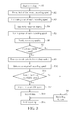
- FIG. 3 is a flowchart illustrating a recording method of an optical disc drive according to a first embodiment of the invention.
- FIG. 4 is a flowchart illustrating a recording method of an optical disc drive according to a second embodiment of the invention.
- FIG. 2 is a data structure of an optical disc.
- a circular optical disc has a spiral data track which starts from a position close to a center hole of the optical disc to an outer rim of the optical disc.
- the data track is divided into an inner track area 10 , a lead-in area 11 , a data area 12 , a lead-out area 13 and an outer track area 14 from an inner track to an outer track.
- Inner track area 10 and outer track area 14 are used for recording tests for deriving optimum write power of the optical disc.
- Lead-in area 11 is to record a table of content (TOC) and characteristic information of the optical disc, where some blanks are reserved therein.
- Data area 12 is the actual portion where the optical disc drive records data.
- the lead-out area 13 following the data area 12 is used to mark the end of data recording, where some blanks are reserved therein.
- a recording method of an optical disc drive searches the lead-out area 13 for a reserved blank area available for data recording as a verification area used to verify the optimum write power obtained by the recording test at the inner track area 10 or outer track area 14 and the estimated write powers of higher recording speeds, where the test data has restricted data amount and does not occupy much disc space, and the reserved blank area in the lead-out area 13 is therefore enough for all the test data.
- the optimum write power obtained by the recording test at the inner track area 10 or outer track area 14 and estimated write power of higher recording speeds are used to record test data into the reserved blank area found in the lead-out area 13 respectively, and then signals of the recorded test data are read out to check if the recording quality parameter of each recording speed is within a default range. If the recording quality parameter is within the default range, it means that the recording quality at the specific recording speed is normal to therefore make the retrieved data recognizable, and the write power can be used for data recording at the specific recording speed. However, if the recording quality parameter is out of the default range, this means that the recording quality at the specific recording speed is too bad to make the retrieved data recognizable, and the specific recording speed should be prohibited from being used in data recording.
- the recording method of the optical disc drive according to the invention checks which pre-defined recording speed area the recording address belongs to as soon as entering a data recording position while recording data onto the optical disc. That is, the recording method of the optical disc drive according to the invention searches a corresponding verified recording speed used for performing data recording. If the recording quality parameter of the corresponding verified recording speed is out of the default range at a verification phase and deleted, the searching procedure proceeds with recording speeds lower than the corresponding verified recording speed sequentially to find a substitute recording speed suitable for data recording at the current recording address. Although the recording time gets even longer due to recording data at a lower recording speed, the readability of data recorded on the optical disc is maintained, avoiding producing an optical disc with unreadable data.
- the time that was wasted recording data onto the optical disc and that the optical disc wasted on recording the data can be saved. If the searching procedure finds that there is no lower recording speed available for acting as a substitutive recording speed, an error message indicative of the recording failure is reported to a computer host, and the data recording operation is terminated to prevent the data from being recorded using an unsuitable recording speed and write power. Thus, the time that was wasted recording data onto the optical disc and that the optical disc wasted on storing the data can be prevented.
- FIG. 3 is a flowchart illustrating a recording method of an optical disc drive according to a first embodiment of the invention.
- the detailed steps directed to deleting unsuitable recording speeds by verifying the optimum write power obtained from the recording test and the estimated write powers of higher recording speeds are as follows.
- step R 1 an optical disc drive is started up and proceeds with recording data onto an optical disc.
- step R 2 the optical disc drive uses the lowest recording speed, such as 2 ⁇ , to perform an OPC operation at the inner track area or the outer track area of the optical disc for obtaining the optimum write power corresponding to the lowest recording speed.
- step R 3 with the recording speeds assigned to the divided sections on the optical disc in advance and the characteristics of the data transfer rate taken into consideration, the write power of each higher recording speed can be estimated according to the optimum write power of the lowest recording speed that is derived in Step R 2 and a ratio of the lowest recording speed and the higher recording speed.
- step R 4 by way of example, the present embodiment searches reserved blanks in the lead-out area to serve as a verification area.
- verification is initiated to record test data into the reserved blanks of the lead-out area using the lowest recording speed with its corresponding optimum write power and the higher recording speeds respectively with corresponding estimated write powers.
- step R 6 signals of recorded data corresponding to recording speeds under test are read out for determining the recording quality parameters which are used for judging the recording qualities for the write powers at different recording speeds.
- step R 7 each of the recording qualities corresponding to the predetermined recording speeds is checked to see if it is within a default range. In other words, step R 7 is to check if there is any suitable recording speed available in the predetermined recording speeds.
- step R 8 If there is no suitable recording speed, the flow proceeds with step R 8 to inform a computer host of an error message indicative of a recording failure, and then goes to step R 14 to end the recording process. If there is at least one suitable recording speed, the flow proceeds with step R 9 to remove recording speeds with bad recording quality from the predetermined recording speeds, therefore reserving the suitable recording speeds.
- step R 10 the required recording speed for data recording is determined by confirming to which recording speed area of the optical disc the recording data is stored according to the address of the recording data.
- step R 11 a downward sequential search upon recording speeds reserved in step R 9 is started from the required recording speed. If there is no suitable recording speed that can be found, the flow proceeds with step R 8 to inform the computer host of an error message indicative of a recording failure, and then goes to step R 14 to end the recording process. If a suitable recording speed is found, the flow proceeds with step R 12 to replace the previously required recording speed with the searched recording speed and the write power corresponding to the searched recording speed is used instead.
- step R 13 data recording proceeds. After the data recording is completed, the flow enters step R 14 to end the recording process.
- FIG. 4 is a flowchart illustrating a recording method of an optical disc drive according to a second embodiment of the invention.
- the recording test, write power estimation, searching for blanks, verification, and excluding unsuitable recording speeds are substantially identical to that described in the first embodiment mentioned above.
- the major difference is that the data to be recorded onto the optical disc has a longer data length, and has to be recorded to different recording speed areas.
- the flow pauses the data recording, performs a sequential search to find a lower recording speed used for replacing the deleted high recording speed, and then resumes the data recording. In this way, the overall recording time can be reduced.
- step S 1 an optical disc drive is started up and proceeds with recording data onto an optical disc.
- step S 2 unsuitable recording speeds are deleted and suitable recording speeds are reserved through the recording test, estimation, searching for blanks, and verification.
- step S 3 the required recording speed for data recording is determined by confirming to which recording speed area of the optical disc the recording data is presumed to be recorded according to the address of the recording data.
- step S 4 a search is made of the reserved suitable recording speeds for the required recording speed. If no suitable recording speed is found, the flow proceeds with step S 5 to search for a lower recording speed.
- step S 6 If there is still no suitable recording speed found, the flow goes to step S 6 to inform a computer host of an error message indicative of a recording failure, and then enters step S 7 to end the recording process. If a suitable recording speed (i.e., the required recording speed) is successfully found in step S 4 or a lower recording speed is successfully found in step S 5 , the flow proceeds with step S 8 to use the searched suitable recording speed (i.e., the required recording speed) or the searched lower recording speed which replaces the required recording speed, and the write power is set to the power corresponding to the searched suitable recording speed/lower recording speed. The flow then enters step S 9 to perform data recording.
- a suitable recording speed i.e., the required recording speed
- step 10 the recording is monitored to see if all of the data have been recorded onto the optical disc. If yes, the flow proceeds with step S 7 to end the recording process; otherwise, the flow proceeds with step S 11 to check whether the recording position has arrived at the boundary between two adjacent recording speed areas on the optical disc. If the recording position has not arrived at the boundary of two adjacent recording speed areas, the flow goes back to step S 9 to keep recording data onto the optical disc at the original recording speed. However, if the recording position arrives at the boundary between two adjacent recording speed areas, the flow enters step S 12 to pause the data recording and go back to step S 3 to confirm the required recording speed of the recording data by the address of the recording speed area and search for a suitable recording speed or a lower recording speed to carry on the data recording.
- the recording method of the optical disc drive according to the present invention reads the recording quality of the signals of the test data that resulted from the recording test, deletes recording speeds with bad recording quality, and replaces deleted unsuitable recording speeds with recording speeds with acceptable recording quality or lower recordable speeds.
- the substitute recording speed instead of the unsuitable recording speed, is employed, the recording quality is secured.
- the present invention is also allowed to utilize lead-out areas in an optical disc to directly record results of the recording test and the write power estimation for verifying each recording speed's suitability.
- the recording method of the present invention does not have to test each recording speed, which greatly reduces the amount of test data to be recorded and disc space occupied by the recorded test data; in addition, the recording method of the present invention does not affect the storage capacity for normal data storage and normal data recording operation of the optical disc drive.
Landscapes
- Physics & Mathematics (AREA)
- Optics & Photonics (AREA)
- Optical Recording Or Reproduction (AREA)
Abstract
Description
Claims (9)
Applications Claiming Priority (3)
| Application Number | Priority Date | Filing Date | Title |
|---|---|---|---|
| TW96150439A | 2007-12-25 | ||
| TW096150439 | 2007-12-25 | ||
| TW096150439A TWI360815B (en) | 2007-12-25 | 2007-12-25 | Recording method of optical disk drive |
Publications (2)
| Publication Number | Publication Date |
|---|---|
| US20090161510A1 US20090161510A1 (en) | 2009-06-25 |
| US8068394B2 true US8068394B2 (en) | 2011-11-29 |
Family
ID=40788464
Family Applications (1)
| Application Number | Title | Priority Date | Filing Date |
|---|---|---|---|
| US12/269,059 Expired - Fee Related US8068394B2 (en) | 2007-12-25 | 2008-11-12 | Recording method of optical disc drive |
Country Status (2)
| Country | Link |
|---|---|
| US (1) | US8068394B2 (en) |
| TW (1) | TWI360815B (en) |
Citations (3)
| Publication number | Priority date | Publication date | Assignee | Title |
|---|---|---|---|---|
| US20030123352A1 (en) * | 2001-12-28 | 2003-07-03 | Chien-Shou Chen | Method for controlling writing power in CAV mode |
| US20050259537A1 (en) * | 2004-05-19 | 2005-11-24 | Kim Joung W | Method and apparatus of determining writing power for a recording medium |
| US20080101174A1 (en) * | 2006-10-27 | 2008-05-01 | Hon Hai Precision Industry Co., Ltd. | Optimal power calibration method and data recording apparatus using the same |
-
2007
- 2007-12-25 TW TW096150439A patent/TWI360815B/en not_active IP Right Cessation
-
2008
- 2008-11-12 US US12/269,059 patent/US8068394B2/en not_active Expired - Fee Related
Patent Citations (3)
| Publication number | Priority date | Publication date | Assignee | Title |
|---|---|---|---|---|
| US20030123352A1 (en) * | 2001-12-28 | 2003-07-03 | Chien-Shou Chen | Method for controlling writing power in CAV mode |
| US20050259537A1 (en) * | 2004-05-19 | 2005-11-24 | Kim Joung W | Method and apparatus of determining writing power for a recording medium |
| US20080101174A1 (en) * | 2006-10-27 | 2008-05-01 | Hon Hai Precision Industry Co., Ltd. | Optimal power calibration method and data recording apparatus using the same |
Also Published As
| Publication number | Publication date |
|---|---|
| TW200929189A (en) | 2009-07-01 |
| US20090161510A1 (en) | 2009-06-25 |
| TWI360815B (en) | 2012-03-21 |
Similar Documents
| Publication | Publication Date | Title |
|---|---|---|
| US20060203640A1 (en) | Apparatus for recording data with respect to information storage medium | |
| KR100602407B1 (en) | An information recording medium, an information recording and reproducing method, and an information recording and reproducing apparatus | |
| US8391113B2 (en) | Optical disc for tuple-speed recording and optical disc device for tuple-speed recording | |
| US7336575B2 (en) | Information recording/reproducing apparatus that improves recording/reproducing characteristics | |
| US7154833B2 (en) | Laser power selecting method, information recording medium, and information recording device | |
| US8068394B2 (en) | Recording method of optical disc drive | |
| KR100512211B1 (en) | Optical information recording reproducing apparatus and recording method | |
| US7397740B2 (en) | Method and recording device capable of selecting a write strategy applied to an optical disc | |
| JP4342930B2 (en) | Optical disc apparatus, control method therefor, and recording medium | |
| US7167422B2 (en) | Optical recording apparatus capable of optimizing write defocus and method thereof | |
| US20060077882A1 (en) | Optical recording medium, recording/reproducing method and recording/reproducing apparatus | |
| JP2006302332A (en) | Recording / playback device | |
| JP4611297B2 (en) | ACCESS DEVICE, ACCESS METHOD, ACCESS PROGRAM, AND CONTROL DEVICE | |
| US20060280108A1 (en) | Optical disc | |
| JP4067981B2 (en) | Optical disc apparatus and recording condition setting method | |
| JPH09198660A (en) | Optical disk drive | |
| US20080151725A1 (en) | Apparatus And Method For Optimized Write Strategy Control | |
| CN101494062B (en) | CD-ROM Burning Method | |
| JP3873672B2 (en) | Optical disk device | |
| CN1656546A (en) | Optical disc system with improved playback capabilities | |
| KR100318203B1 (en) | Recording Control Method of Optical Disc | |
| JP2003151133A (en) | Information recording / reproducing device | |
| KR20070084345A (en) | Speed control based on data error measurements | |
| JP2007501482A (en) | Apparatus and method for recording data blocks | |
| KR20060079620A (en) | Optical disc with divided recording method tuning area, optical recording and reproducing apparatus using same, and method |
Legal Events
| Date | Code | Title | Description |
|---|---|---|---|
| AS | Assignment |
Owner name: QUANTA STORAGE INC.,TAIWAN Free format text: ASSIGNMENT OF ASSIGNORS INTEREST;ASSIGNORS:CHEN, SHIH-KUO;HSU, CHIN-FA;CHU, SHIU-MING;REEL/FRAME:021819/0324 Effective date: 20081106 Owner name: QUANTA STORAGE INC., TAIWAN Free format text: ASSIGNMENT OF ASSIGNORS INTEREST;ASSIGNORS:CHEN, SHIH-KUO;HSU, CHIN-FA;CHU, SHIU-MING;REEL/FRAME:021819/0324 Effective date: 20081106 |
|
| REMI | Maintenance fee reminder mailed | ||
| LAPS | Lapse for failure to pay maintenance fees | ||
| STCH | Information on status: patent discontinuation |
Free format text: PATENT EXPIRED DUE TO NONPAYMENT OF MAINTENANCE FEES UNDER 37 CFR 1.362 |
|
| STCH | Information on status: patent discontinuation |
Free format text: PATENT EXPIRED DUE TO NONPAYMENT OF MAINTENANCE FEES UNDER 37 CFR 1.362 |
|
| FP | Lapsed due to failure to pay maintenance fee |
Effective date: 20151129 |