US8067940B2 - Tubular magnetic resonance surface coil, and method and system for processing signals therefrom - Google Patents
Tubular magnetic resonance surface coil, and method and system for processing signals therefrom Download PDFInfo
- Publication number
- US8067940B2 US8067940B2 US12/436,969 US43696909A US8067940B2 US 8067940 B2 US8067940 B2 US 8067940B2 US 43696909 A US43696909 A US 43696909A US 8067940 B2 US8067940 B2 US 8067940B2
- Authority
- US
- United States
- Prior art keywords
- coil
- output signals
- channels
- units
- radio frequency
- Prior art date
- Legal status (The legal status is an assumption and is not a legal conclusion. Google has not performed a legal analysis and makes no representation as to the accuracy of the status listed.)
- Expired - Fee Related, expires
Links
Images


Classifications
-
- G—PHYSICS
- G01—MEASURING; TESTING
- G01R—MEASURING ELECTRIC VARIABLES; MEASURING MAGNETIC VARIABLES
- G01R33/00—Arrangements or instruments for measuring magnetic variables
- G01R33/20—Arrangements or instruments for measuring magnetic variables involving magnetic resonance
- G01R33/28—Details of apparatus provided for in groups G01R33/44 - G01R33/64
- G01R33/32—Excitation or detection systems, e.g. using radio frequency signals
- G01R33/34—Constructional details, e.g. resonators, specially adapted to MR
- G01R33/341—Constructional details, e.g. resonators, specially adapted to MR comprising surface coils
- G01R33/3415—Constructional details, e.g. resonators, specially adapted to MR comprising surface coils comprising arrays of sub-coils, i.e. phased-array coils with flexible receiver channels
-
- G—PHYSICS
- G01—MEASURING; TESTING
- G01R—MEASURING ELECTRIC VARIABLES; MEASURING MAGNETIC VARIABLES
- G01R33/00—Arrangements or instruments for measuring magnetic variables
- G01R33/20—Arrangements or instruments for measuring magnetic variables involving magnetic resonance
- G01R33/28—Details of apparatus provided for in groups G01R33/44 - G01R33/64
- G01R33/32—Excitation or detection systems, e.g. using radio frequency signals
- G01R33/36—Electrical details, e.g. matching or coupling of the coil to the receiver
- G01R33/3621—NMR receivers or demodulators, e.g. preamplifiers, means for frequency modulation of the MR signal using a digital down converter, means for analog to digital conversion [ADC] or for filtering or processing of the MR signal such as bandpass filtering, resampling, decimation or interpolation
-
- G—PHYSICS
- G01—MEASURING; TESTING
- G01R—MEASURING ELECTRIC VARIABLES; MEASURING MAGNETIC VARIABLES
- G01R33/00—Arrangements or instruments for measuring magnetic variables
- G01R33/20—Arrangements or instruments for measuring magnetic variables involving magnetic resonance
- G01R33/44—Arrangements or instruments for measuring magnetic variables involving magnetic resonance using nuclear magnetic resonance [NMR]
- G01R33/48—NMR imaging systems
- G01R33/54—Signal processing systems, e.g. using pulse sequences ; Generation or control of pulse sequences; Operator console
- G01R33/56—Image enhancement or correction, e.g. subtraction or averaging techniques, e.g. improvement of signal-to-noise ratio and resolution
- G01R33/5608—Data processing and visualization specially adapted for MR, e.g. for feature analysis and pattern recognition on the basis of measured MR data, segmentation of measured MR data, edge contour detection on the basis of measured MR data, for enhancing measured MR data in terms of signal-to-noise ratio by means of noise filtering or apodization, for enhancing measured MR data in terms of resolution by means for deblurring, windowing, zero filling, or generation of gray-scaled images, colour-coded images or images displaying vectors instead of pixels
Definitions
- the present invention relates to the magnetic resonance imaging (MRI) technology, and particularly to a tubular surface coil and a method and system for processing radio frequency (RF) signals of such a tubular surface coil.
- MRI magnetic resonance imaging
- RF radio frequency
- the basic principle of MRI is that hydrogen atoms (or other atoms, but hydrogen atoms are most commonly used) in human tissues will be directionally aligned under the effects of a fixed magnetic field.
- these hydrogen atoms will be deviated due to the effects of the radio frequency pulses.
- the radio frequency pulses vanishes, these hydrogen atoms will recover to the original state.
- sampling radio frequency signals generated by these hydrogen atoms and then reconstructing an image using the acquired signals can result in an image of the human tissues. Since the distribution of hydrogen atoms in different tissues varies, different human tissues can be distinguished through the obtained images.
- a coil is a device for acquiring such signals, the basic principle being similar to that of a radial field receiving antenna.
- such coils can be divided into body coils, and surface coils, etc., and according to the shape, the coils can be divided into: tubular coils, planar coils, helmet-shaped coils, fan-shaped coils, etc.
- a knee coil is a tubular surface coil, and by taking the knee coil as an example hereinbelow, the structure and imaging features of conventional tubular surface coils will be explained.
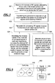
- FIG. 1 shows a diagram of the construction structure of an existing knee coil. Referring to FIG. 1 , wherein:
- part (a) is the appearance of a conventional knee coil, which is tubular;
- part (b) is a schematic diagram of the exploded structure of the existing knee joint coil; according to the exploded schematic diagram, the construction units of the coil are coil units, and in FIG. 1 , the number of coil units is six as an example, and E 1 to E 6 represent the coil units; and
- part (c) is a diagram of positional relationship between the coil units when the six coil units are arranged into a tubular shape.
- each coil unit acquires corresponding radio frequency signals, and the acquired radio frequency signals are vectors and are sent to a system for processing radio frequency signals in the MRI equipment, therefore, these signals sent by the coil to the system for processing radio frequency signals are referred to as coil output signals.
- the system for processing radio frequency signals is used for performing radio frequency signals processing of the coil output signals which are then sent to an image reconstruction system to reconstruct an image, and FIG. 2 shows a schematic diagram of an existing system 200 for processing radio frequency signals.
- the existing system 200 for processing radio frequency signals comprises: N receiving channels 210 and a radio frequency signal processing module 220 .
- the N receiving channels 210 are used for receiving N channels of the coil output signals coming from the coil, and sending the N channels of coil output signals to the radio frequency signal processing module 220 .
- N is an integer greater than 1 and less than or equal to the number of coil units in the coil (the number of coil units in the coil is set as M below, with M being an integer greater than 1). If the number N of receiving channels is equal to the number M of coil units in the coil, M channels of radio frequency signals can be taken directly as the coil output signals, and sent to the corresponding N receiving channels, and if the number N of receiving channels is less than the number M of coil units in the coil, N channels of coil output signals can be generated after certain signal synthesizing of M channels of radio frequency signals, and sent to the corresponding N receiving channels.
- the radio frequency signal processing module 220 is used for performing radio frequency signal processing on the received coil output signals.
- said radio frequency signal processing is as follows: summing the square of the modulus values of each of the received channel of coil output signals, and computing the square root of the obtained sum. The result of the square root computation can be used in performing image reconstruction.
- said radio frequency signal processing is as follows: calculating square (S 01 2 +S 02 2 + . . . +S 06 2 ), wherein “square” represents the square root computation, and where S 01 , S 02 , . . . , S 06 represent the radio frequency signals from coil units E 1 , E 2 . . . E 6 , respectively.
- the image reconstruction will obtain three types of basic images: lateral cross-sectional plane images, sagittal plane images and coronal plane images, and the images in other sections can also be obtained by performing a certain transformation on said three types of basic images.
- the signal strength acquired by the coil units in the surface coil at a close distance is much greater than that acquired at a farther distance. This results, in the images obtained according to the abovementioned method, in both the signal strength between different areas (for example, the surface area and central area of the tubular surface coil) and the signal to noise ratio (SNR) proportional to the signal strength are significantly different, that is, the signal strength and the uniformity of signal to noise ratio within an imaging area are relatively poor.
- SNR signal to noise ratio
- FIG. 3 and FIG. 4 are computer screenshots, respectively showing diagrams of the distribution of signal to noise ratio of the lateral cross-sectional images and the sagittal plane image of an existing knee coil. Since the distribution of signal to noise ratio of the coronal plane images has the same features as that of the sagittal plane images, a diagram of the signal to noise ratio distribution of the coronal plane image is not shown in this application document.
- FIGS. 3 and 4 the signal to noise ratio inside tissues and on the surface of tissues are illustrated in the form of contour lines, and the higher density of curves represents the greater difference. It can be seen from FIGS.
- the signal strength on the tissue surface is much greater than that inside the tissue, and accordingly, the signal to noise ratio on the tissue surface of is also much greater than that inside the tissues.
- both the signal strength and the uniformity of the signal to noise ratio within the imaging area are relatively poor.
- An object of the present invention is to provide a method for processing radio frequency signals of a tubular surface coil, a system for processing radio frequency signals of the tubular surface coil, and a tubular surface coil, with which the signal strength and uniformity of the signal to noise ratio are improved within the imaging area of the lateral cross-sectional image.
- the tubular surface coil has M coil units, M being an even number greater than 1, and the M coil units are divided into M/2 pairs, with two coil units in each of the pairs being disposed at symmetrical positions in said tubular surface coil.
- the method includes the steps of generating N channels of coil output signals based on M channels of radio frequency signals, acquired by the M coil units, wherein N is an even number greater than 1 and less than or equal to M, and the N channels of coil output signals can be divided into N/2 pairs, with the two channels of coil output signals in each of the pairs respectively coming from the coil units at the symmetrical positions in said tubular surface coil, and multiplying respectively the modulus values of the two channels of coil output signals in each pair of coil output signals to obtain N/2 products which are then summed, and computing the square root of the summed result, with the computed result of square root being used to generate a lateral cross-sectional image.
- the method can further include summing the modulus values of the N channels of coil output signals, and the summed result being used to generate a sagittal plane image and/or a coronal plane image.
- the step of generating N channels of coil output signals includes taking radio frequency signals acquired by each of the coil units as one channel of the coil output signals.
- the step of generating N channels of coil output signals includes dividing all or a part of the M coil units into N groups, wherein there are at least two groups which comprise one coil unit, and there are at least two groups which contain more than one coil units, and dividing the N groups into N/2 pairs, with the two groups of the coil units in each of the pairs being located at the symmetrical positions of the tubular surface coil.
- radio frequency signals acquired by the coil unit in the group are used as one channel of the coil output signals
- the radio frequency signals acquired by all the coil units in the group are synthesized into one channel of the coil output signals.
- the step of generating N channels of coil output signals includes dividing a part of the M coil units into N groups, with each group having one coil unit, and dividing the N groups into N/2 pairs, with the two groups of the coil units in each of the pairs being located at the symmetrical positions of said tubular surface coil.
- the radio frequency signals acquired by each of the groups of coil unit are used as one channel of the coil output signals.
- the step of generating N channels of coil output signals includes dividing all or a part of the M coil units into N groups, with each group having more than one coil units, and dividing the N groups into N/2 pairs, with the two groups of the coil units in each of the pairs being located at the symmetrical positions of the tubular surface coil.
- the radio frequency signals acquired by all the coil units in each of the groups are synchronized into one channel of the coil output signals.
- the invention also encompasses a system for processing radio frequency signals in a tubular surface coil, wherein the tubular surface coil comprises M coil units, and M is an even number greater than 1, and the M coil units can be divided to M/2 pairs, with the two coil units in each of the pair being located at symmetrical positions of the tubular surface coil.
- the system for processing radio frequency signals has N receiving channels, wherein N is an even number greater than 1 and less than or equal to M, and the system for processing radio frequency signals receives N channels of coil output signals from the tubular surface coil via the N receiving channels.
- the N channels of the coil output signals can be divided into N/2 pairs, with the two channels of coil output signals in each of the pairs respectively coming from the coil units located at the symmetrical positions of said tubular surface coil.
- a multiplication unit multiplies the modulus values of the two channels of coil output signals in each of the channel pairs of output signals respectively, to obtain N/2 products/
- a first addition unit sums the N/2 products, to obtain a summed result.
- a square root computation unit computes the square root of said summed result, said computed result of square root being used to generate a lateral cross-sectional image.
- the system for processing radio frequency signals can further have a second addition unit, for summing the modulus values of the N channels of coil output signals, with the summed result being used to generate a sagittal plane image and/or a coronal plane image.
- the invention also encompasses tubular surface coil, having M coil units, wherein M is an even number greater than 1, and the M coil units can be divided into M/2 pairs, with the two coil units in each of the pairs being located at symmetrical positions of the surface coil.
- the tubular surface coil further has a memory module that stores N coil output signals, and the grouping relationship when a part or all of said M coil units are divided into N groups, wherein N is an even number greater than 1 and less than or equal to M, and the N groups can be divided into N/2 pairs, with the two groups of coil units in each of the pairs being located at the symmetrical positions of said tubular surface coil.
- a signal generating module that, according to the grouping relationship, takes the radio frequency signals acquired by a group that has only one coil unit as one channel of the coil output signals, and/or synthesizes the radio frequency signals acquired by a group that has more than one coil units, into one channel of the coil output signals.
- the M coil units constitute a number of tubular components, and each of the tubular components has a number of coil units.
- the multiple tubular components have a coincident axis, and they are adjacent one another in succession in the direction of the axis, and the adjacent tubular components stagger half a coil unit in the tangential direction of the circumference in a lateral cross-sectional plane.
- the sum of square of the radio frequency signals from the coil units that is obtained in the prior art is replaced with the sum of products of modulus values of radio frequency signals from the coil units at the symmetrical positions.
- the present invention also reduces the influence on the difference of signal strengths acquired by the coil units at a close distance and at a farther distance by summing modulus values of the N channels of coil output signals and generating the sagittal plane image and/or coronal plane image according to the summed result, thereby improving the signal strength and the uniformity of signal to noise ratio within the imaging areas in the sagittal plane and coronal plane.
- FIG. 1 shows a construction schematic diagram of a known knee coil.
- FIG. 2 shows a construction schematic diagram of an existing system for processing radio frequency signals.
- FIG. 3 is a computer screenshot showing the distribution of the signal to noise ratio of a lateral cross-sectional image of the known knee coil, wherein the horizontal coordinate and vertical coordinate are in millimeters.
- FIG. 4 is a computer screenshot showing the distribution of the signal to noise ratio of a sagittal plane image of the known knee coil, wherein the horizontal coordinate and vertical coordinate are in millimeters.
- FIG. 5 is a flowchart of a method for processing radio frequency signals of the present invention.
- FIG. 6 is a system schematic diagram of a tubular surface coil of the present invention.
- FIG. 7 is a computer screenshot showing the distribution of the signal to noise ratio of a knee lateral cross-sectional image obtained by using the technical solutions of the present invention, wherein the horizontal coordinate and vertical coordinate are in millimeters.
- FIG. 8 is a computer screenshot showing signal to noise ratio distribution of a knee sagittal plane image obtained by using the technical solutions of the present invention, wherein the horizontal coordinate and vertical coordinate are in millimeters.
- FIG. 9 shows a construction schematic diagram of a preferred tubular surface coil of the present invention.
- FIG. 10 shows a schematic structural diagram of a system for processing radio frequency signals in the embodiments of the present invention.
- the basic concept of the present invention is that during the processing of the radio frequency signals of a tubular surface coil, the corresponding processing is performed on multiple channels of coil output signals of the tubular surface coil, so as to reduce the influence on the differences of signal strengths acquired by the coil units at a close distance and a farther distance, thereby improving the signal strengths and the uniformity of signal to noise ratio in the imaging area of the lateral cross-sectional image.
- the tubular surface coil suitable for the present invention have M coil units (M is an even number greater than 1), and each coil unit acquires one channel of radio frequency signals.
- M is an even number greater than 1
- the M coil units in the tubular surface coil can be divided into M/2 pairs, and the two coil units in each pair of coil units are located at symmetrical positions in the tubular surface coil. This means, it is necessary to divide the M coil units in the tubular surface coil into M/2 pairs, with two coil units in each pair of coil units being disposed at the symmetrical positions in the tubular surface coil. It should be noted that, due to the difference in manufacturing process and particular cases in use, this symmetry is not absolute, and a certain difference is permissible, as long as it will not influence the effects of the present invention.
- FIG. 5 is a flowchart of the method for processing radio frequency signals of the present invention. Referring to FIG. 5 , the method includes the steps of:
- Step 501 generating N channels of coil output signals based on M channels of radio frequency signals acquired by M coil units in the tubular surface coil (N is an even number greater than 1 and less than or equal to M), such that the generated N channels of coil output signals can be divided into N/2 pairs, with two channels of coil output signals in each pair respectively coming from the coil units located at the symmetrical positions in the tubular surface coil.
- E 1 and E 4 are the coil units located at the symmetrical positions in the tubular surface coil in the embodiment of the present invention
- E 2 and E 5 , E 3 and E 6 are respectively two pairs of the coil units located at symmetrical positions in the tubular surface coil in the embodiment of the present invention.
- Step 502 transmitting respectively the generated N channels of coil output signals from the tubular surface coil via N receiving channels to the system for processing radio frequency signals, wherein each receiving channel transmits one channel of coil output signals.
- Step 503 receiving by the system for processing radio frequency signals the N channels of coil output signals coming from the tubular surface coil.
- Step 504 firstly, multiplying modulus values of two channels of coil output signals in each pair of coil output signals of step 501 , respectively, to obtain N/2 products.
- the multiplied two channels of coil output signals respectively come from the coil units located at the symmetrical positions in the canister surfaced coil.
- the computed result of square root can further be sent to an image reconstruction system to generate lateral cross-sectional images.
- the process for generating lateral cross-sectional images according to the computed result of square root is similar to the process for generating lateral cross-sectional images according to square (S 012 +S 022 + . . . +S 062 ) in the prior art, that is, using the computed result of square root to perform the subsequent processing of image reconstruction, so as to generate corresponding images.
- step 503 can be followed by step 505 : summing modulus values of said N channels of coil output signals.
- the summed result can be further sent to the image reconstruction system, for generating sagittal plane images and/or coronal plane images.
- the process for generating sagittal plane images and/or coronal plane images according to the summed result is similar to the process for generating sagittal plane images and/or coronal plane images according to square (S 012 +S 022 + . . . +S 062 ) in the prior art, that is, using the summed result to perform the subsequent processing of image reconstruction, so as to generate corresponding images.
- the priority of step 504 or step 505 is not restricted, and the priority of reconstructing lateral cross-sectional images, sagittal plane images or coronal plane images during the subsequent image reconstruction is also not restricted.
- step 504 in the method for processing radio frequency signals of the present invention is as follows: computing square (S 01 *S 04 +S 02 *S 05 +S 03 *S 06 ), and the computed result of square (S 01 *S 04 +S 02 *S 05 +S 03 *S 06 ) can be further sent to the image reconstruction system to generate the lateral cross-sectional images, wherein, S 01 , S 02 , . . . , S 06 represent the radio frequency signals coming from coil units E 1 , E 2 , E 6 , respectively.
- step 505 in the method for processing radio frequency signals of embodiments of the present invention is as follows.
- the quantity abs(S 01 )+abs(S 02 )+abs(S 03 )+abs(S 04 )+abs(S 05 )+abs(S 06 ) is calculated as a computed result that is supplied to the image reconstruction system, for generating the sagittal plane images and/or coronal plane images, wherein S 01 , S 02 , . . . , S 06 represent radio frequency signals coming from coil units E 1 , E 2 , . . . , E 6 , respectively.
- N of receiving channels in the system for processing radio frequency signals is less than the number M of coil units in the tubular surface coil, and in such a case, N channels of coil output signals can be generated based on M channels of radio frequency signals acquired by coil units in the following manner.
- the first step dividing all or a part of M coil units into N groups in advance, wherein each group can have one coil unit, or more than one coil units.
- each group comprises only one coil unit. If the radio frequency signals acquired by one certain coil unit cannot be used, then this division may not involve this coil unit.
- the division makes the obtained N groups divided into N/2 pairs, with the two groups of coil units in each pair being located at the symmetrical positions in the tubular surface coil.
- the second step in each divided group, generating one channel of coil output signals according to the radio frequency signals acquired by the coil units in the group.
- the radio frequency signals acquired by the one coil unit in the group are taken directly as one channel of coil output signals.
- the radio frequency signals acquired by all the coil units in the group are synthesized as one channel of coil output signals. Due to the symmetrical relationship during their division, the N channels of coil output signals obtained finally can be divided into N/2 pairs, with the two channels of coil output signals in each pair respectively coming from coil units located at the symmetrical positions in the tubular surface coil.
- all six coil units can be divided into 4 groups, and the grouping relationship is: the first group is E 1 and E 2 , the second group is E 3 , the third group is E 4 and E 5 , and the forth group is E 6 .
- the two channels of radio frequency signals acquired by E 1 and E 2 are synthesized into one channel of coil output signals (marked as S 1 ); in the second group, radio frequency signals acquired by E 3 are directly taken as one channel of coil output signals (marked as S 2 ).
- the two channels of radio frequency signals acquired by E 4 and E 5 are synthesized into one channel of coil output signals (marked as S 3 ).
- radio frequency signals acquired by E 6 are directly taken as one channel of coil output signals (marked as S 4 ).
- the relationships between each of coil units and coil output signals can be expressed as: E1, E2 ⁇ S1 E3 ⁇ S2 E4, E5 ⁇ S3 E6 ⁇ S4
- S 1 , S 2 , S 3 and S 4 are in accordance with the condition in the embodiments of the present invention that “N channels of coil output signals can be divided into N/2 pairs, with the two channels of coil output signals in each pair respectively coming from the coil units located at the symmetrical positions in the tubular surface coil”, and S 1 , S 2 , S 3 and S 4 can be used to execute step 502 and subsequent steps thereof.
- E 1 and E 3 , and E 4 and E 6 respectively located at the symmetrical positions in the tubular surface coil can be directly selected as one group, so there are four groups. Since E 1 and E 4 are located at symmetrical positions in the tubular surface coil, and E 3 and E 6 are also located at symmetrical positions in the tubular surface coil, the radio frequency signals S 01 , S 02 , S 03 and S 04 coming from selected E 1 , E 3 , E 4 and E 6 are used as four channels of emitted coil output signals which are in accordance with the condition that “N channels of coil output signals can be divided into N/2 pairs, with the two channels of coil output signals in each pair respectively coming from coil units located at symmetrical positions in the tubular surface coil”. Of course, in practical use, there exist a variety of manners of generating N channels of coil output signals, which will not be described herein redundantly.
- the present invention provides a tubular surface coil 600 shown in FIG. 6 .
- the tubular surface coil 600 has M coil units 610 , and also comprises a memory module 620 and a signal generating module 630 .
- M coil units can be divided into M/2 pairs, with the two coil units in each pair of coil units being located at symmetrical positions in the tubular surface coil 600 .
- the memory module 620 is used for storing the number N of coil output signals and the grouping relationship when all M or a part of M coil units are divided into N groups, wherein N is an even number greater than 1 and less than or equal to M, and said N groups can be divided into N/2 pairs, with the two groups of coil units in each pair being located at symmetrical positions in the tubular surface coil 600 .
- the signal generating module 630 is used for, in accordance with the grouping relationship in the memory module 620 , taking the radio frequency signals acquired by the coil unit in the group which comprises only one coil unit as one channel of coil output signals, and/or synthesizing the radio frequency signals acquired by all the coil units in the group that has more than one coil units into one channel of coil output signals.
- FIG. 7 is a computer screenshot showing the distribution of the signal to noise ratio of a knee lateral cross-sectional image obtained by using the technical solutions of the embodiment of the present invention
- FIG. 8 is a computer screenshot showing the distribution of the signal to noise ratio of a knee sagittal plane image obtained by using the technical solutions of the embodiments of the present invention.
- a tubular surface coil which contains two or more than two tubular components can be constructed to perform the signal acquiring, and the method of the embodiment of the present invention can be applied to process the acquired radio frequency signals.
- the two or more tubular components have a coincident axis, and these tubular components are adjacent to one another in succession in the direction of this axis, and the adjacent tubular components stagger half a coil unit in a tangential direction of the circumference in the lateral cross-section.
- FIG. 9 shows a construction schematic diagram of a preferred tubular surface coil of the present invention. Referring to FIG. 9 , in which:
- part (a) is the appearance of the tubular surface coil, the tubular surface coil being tubular and comprising two tubular components respectively marked as upper tubular component 901 and lower tubular component 902 , wherein the upper tubular component 901 and the lower tubular component 902 have a coincident axis, and the upper tubular component 901 and the lower tubular component 902 are adjacent to each other;
- part (b) is an exploded schematic diagram of the tubular surface coil.
- the upper tubular component 901 and the lower tubular component 902 respectively comprise six coil units, and E 1 to E 6 belong to the upper tubular component 901 , while E 7 to E 12 belong to the lower tubular component 902 .
- the upper tubular component 901 and the lower tubular component 902 stagger half a coil unit from each other, and this is equivalent to the state that in the part (a) of the figure, the upper tubular component 901 and the lower tubular component 902 stagger half a coil unit in the tangential direction of the circumference in the lateral cross-section; and
- part (c) is a diagram of positional relationship between the coil units when said twelve coil units are arranged into a tubular shape.
- the coil unit pairs located at symmetrical positions in the tubular surface coil are E 1 and E 4 , E 2 and E 5 , E 3 and E 6 , E 7 and E 10 , E 8 and E 11 , and E 9 and E 12 .
- the first group of coil units and the second group of coil units can be regarded as being located at symmetrical positions in the tubular surface coil.
- the first group can be E 1 and E 2
- the second group can be E 4 and E 5
- the first group can be E 3 and E 9
- the second group can be E 6 and E 12 .
- the present invention also provides a system for processing radio frequency signals in the tubular surface coil, and the tubular surface coil suitable for the system for processing radio frequency signals has M coil units (M is an even number greater than 1), and each coil unit acquires one channel of radio frequency signals; M coil units in the tubular surface coil can be divided into M/2 pairs, and the two coil units in each pair of coil units are located at symmetrical positions in the tubular surface coil.
- the system 1000 for processing radio frequency signals comprises: N receiving channels 1010 , a multiplication unit 1020 , a first addition unit 1030 , and a square root computation unit 1040 , wherein N is an even number greater than 1 and less than or equal to M.
- N channels of coil output signals coming from the tubular surface coil are received by N receiving channels 1010 , and N channels of coil output signals can be divided into N/2 pairs, with two channels of coil output signals in each pair respectively coming from coil units located at symmetrical positions in the tubular surface coil.
- the multiplication unit 1020 is used for multiplying respectively modulus values of the two channels of coil output signals in each pair of coil output signals, so as to obtain N/2 products, and providing the N/2 products to the first addition unit 1030 .
- the first addition unit 1030 is used for summing the N/2 products received from the multiplication unit 1020 , so as to obtain a summed result, and providing the summed result to the square root computation unit 1040 .
- the square root computation unit 1040 is used for computing the square root of the summed result from the first addition unit 1030 , and the computed result of square root can be sent further to the subsequent image reconstruction system (not shown in the figures), for generating lateral cross-sectional images.
- system 1000 for processing radio frequency signals of the present invention can further comprise a second addition unit 1050 which is used for summing modulus values of N channels of coil output signals obtained from N receiving channels, and the summed result can further be sent to the subsequent image reconstruction system (not shown in the figures), for generating the sagittal plane images and/or the coronal plane images.
- a second addition unit 1050 which is used for summing modulus values of N channels of coil output signals obtained from N receiving channels, and the summed result can further be sent to the subsequent image reconstruction system (not shown in the figures), for generating the sagittal plane images and/or the coronal plane images.
Landscapes
- Physics & Mathematics (AREA)
- Condensed Matter Physics & Semiconductors (AREA)
- General Physics & Mathematics (AREA)
- Health & Medical Sciences (AREA)
- General Health & Medical Sciences (AREA)
- Nuclear Medicine, Radiotherapy & Molecular Imaging (AREA)
- Radiology & Medical Imaging (AREA)
- Engineering & Computer Science (AREA)
- Signal Processing (AREA)
- High Energy & Nuclear Physics (AREA)
- Magnetic Resonance Imaging Apparatus (AREA)
Abstract
Description
E1, E2→S1
E3→S2
E4, E5→S3
E6→S4
Claims (10)
Priority Applications (1)
| Application Number | Priority Date | Filing Date | Title |
|---|---|---|---|
| US12/436,969 US8067940B2 (en) | 2009-05-07 | 2009-05-07 | Tubular magnetic resonance surface coil, and method and system for processing signals therefrom |
Applications Claiming Priority (1)
| Application Number | Priority Date | Filing Date | Title |
|---|---|---|---|
| US12/436,969 US8067940B2 (en) | 2009-05-07 | 2009-05-07 | Tubular magnetic resonance surface coil, and method and system for processing signals therefrom |
Publications (2)
| Publication Number | Publication Date |
|---|---|
| US20100283462A1 US20100283462A1 (en) | 2010-11-11 |
| US8067940B2 true US8067940B2 (en) | 2011-11-29 |
Family
ID=43061966
Family Applications (1)
| Application Number | Title | Priority Date | Filing Date |
|---|---|---|---|
| US12/436,969 Expired - Fee Related US8067940B2 (en) | 2009-05-07 | 2009-05-07 | Tubular magnetic resonance surface coil, and method and system for processing signals therefrom |
Country Status (1)
| Country | Link |
|---|---|
| US (1) | US8067940B2 (en) |
Families Citing this family (2)
| Publication number | Priority date | Publication date | Assignee | Title |
|---|---|---|---|---|
| WO2013098696A1 (en) | 2011-12-30 | 2013-07-04 | Koninklijke Philips Electronics N.V. | Method and apparatus for needle visualization enhancement in ultrasound imaging |
| GB2529135A (en) * | 2014-06-21 | 2016-02-17 | Neil Francis Peirson | Method and apparatus for signal enhancement by reduction of noise |
Citations (3)
| Publication number | Priority date | Publication date | Assignee | Title |
|---|---|---|---|---|
| US6097186A (en) * | 1998-05-20 | 2000-08-01 | Ge Yokogawa Medical Systems, Limited | Phased-array coil, receive signal processing circuit, and MRI apparatus |
| US7109710B2 (en) * | 2003-10-17 | 2006-09-19 | General Electric Company | Method and apparatus to improve signal-to-noise ratio without compromising field-of-view for simultaneous MR data acquisition by an array of RF coils of an MR scanner |
| US7446529B2 (en) * | 2005-07-21 | 2008-11-04 | Kabushiki Kaisha Toshiba | Magnetic resonance imaging apparatus and radio frequency coil unit |
-
2009
- 2009-05-07 US US12/436,969 patent/US8067940B2/en not_active Expired - Fee Related
Patent Citations (4)
| Publication number | Priority date | Publication date | Assignee | Title |
|---|---|---|---|---|
| US6097186A (en) * | 1998-05-20 | 2000-08-01 | Ge Yokogawa Medical Systems, Limited | Phased-array coil, receive signal processing circuit, and MRI apparatus |
| US7109710B2 (en) * | 2003-10-17 | 2006-09-19 | General Electric Company | Method and apparatus to improve signal-to-noise ratio without compromising field-of-view for simultaneous MR data acquisition by an array of RF coils of an MR scanner |
| US7446529B2 (en) * | 2005-07-21 | 2008-11-04 | Kabushiki Kaisha Toshiba | Magnetic resonance imaging apparatus and radio frequency coil unit |
| US7884608B2 (en) * | 2005-07-21 | 2011-02-08 | Kabushiki Kaisha Toshiba | Magnetic resonance imaging apparatus and radio frequency coil unit |
Also Published As
| Publication number | Publication date |
|---|---|
| US20100283462A1 (en) | 2010-11-11 |
Similar Documents
| Publication | Publication Date | Title |
|---|---|---|
| US9254112B2 (en) | Respiratory interval-based correlation and processing of dynamic imaging data | |
| US8116541B2 (en) | Method and apparatus for multi-coil magnetic resonance imaging | |
| JP6232043B2 (en) | Reconstruction of magnetic resonance images using detection of respiratory motion during sampling in the middle and periphery of the K-space region | |
| US9396562B2 (en) | MRI reconstruction with incoherent sampling and redundant haar wavelets | |
| US9482732B2 (en) | MRI reconstruction with motion-dependent regularization | |
| US10483645B2 (en) | Combined loop-dipole antenna array system and methods | |
| US9229081B2 (en) | Accelerated MRI with nonlinear spatial encoding gradients | |
| KR101967245B1 (en) | Magnetic resonance imaging system and magnetic resonance imaging method | |
| US6876199B2 (en) | Method and system for accelerated imaging using parallel MRI | |
| CA2403211A1 (en) | Parallel magnetic resonance imaging techniques using radiofrequency coil arrays | |
| CN106772157B (en) | A kind of method and apparatus of magnetic resonance imaging | |
| US8022700B2 (en) | Method and apparatus for view ordering of magnetic resonance imaging data for dynamic studies | |
| US6914432B2 (en) | Phased array coil assembly and method and system for employing the same | |
| JP6417406B2 (en) | MR imaging with enhanced susceptibility contrast | |
| WO2004060156A1 (en) | Magnetic resonance imaging device | |
| JP6410452B2 (en) | Method for obtaining separation matrix of separation device for coil array of parallel transmission magnetic resonance imaging system (MRI system), configuration method of parallel transmission magnetic resonance imaging system (MRI system) having separation device for coil array, magnetic resonance imaging Computer program for determining separation matrix of separation device for coil array of system (MRI) and parallel transmission magnetic resonance imaging system (MRI) | |
| US20160025829A1 (en) | Systems and methods for efficient radial magnetic resonance imaging with azimuthal equidistant projections | |
| US20160154079A1 (en) | Method and magnetic resonance apparatus for acquiring a sensitivity map for at least one local coil in a magnetic resonance scanner | |
| JP2020101910A (en) | Data processing device, magnetic resonance imaging device, learning device and learning method | |
| JP3992934B2 (en) | Magnetic resonance imaging apparatus and method | |
| US20150309132A1 (en) | Apparatus, method and coil array for providing split parallel transmission magnetic resonance imaging | |
| US8067940B2 (en) | Tubular magnetic resonance surface coil, and method and system for processing signals therefrom | |
| CN100416294C (en) | Magnetic resonance imaging apparatus and method | |
| CN106175765B (en) | Magnetic resonance imaging system and method | |
| US9389292B2 (en) | Efficient method for performing K-space channel combination for non-cartesian MRI acquisitions |
Legal Events
| Date | Code | Title | Description |
|---|---|---|---|
| AS | Assignment |
Owner name: SIEMENS AKTIENGESELLSCHAFT, GERMANY Free format text: ASSIGNMENT OF ASSIGNORS INTEREST;ASSIGNORS:WANG, HAI NING;WANG, JIAN MIN;REEL/FRAME:022926/0758 Effective date: 20090511 |
|
| ZAAA | Notice of allowance and fees due |
Free format text: ORIGINAL CODE: NOA |
|
| ZAAB | Notice of allowance mailed |
Free format text: ORIGINAL CODE: MN/=. |
|
| STCF | Information on status: patent grant |
Free format text: PATENTED CASE |
|
| FPAY | Fee payment |
Year of fee payment: 4 |
|
| AS | Assignment |
Owner name: SIEMENS HEALTHCARE GMBH, GERMANY Free format text: ASSIGNMENT OF ASSIGNORS INTEREST;ASSIGNOR:SIEMENS AKTIENGESELLSCHAFT;REEL/FRAME:039271/0561 Effective date: 20160610 |
|
| MAFP | Maintenance fee payment |
Free format text: PAYMENT OF MAINTENANCE FEE, 8TH YEAR, LARGE ENTITY (ORIGINAL EVENT CODE: M1552); ENTITY STATUS OF PATENT OWNER: LARGE ENTITY Year of fee payment: 8 |
|
| FEPP | Fee payment procedure |
Free format text: MAINTENANCE FEE REMINDER MAILED (ORIGINAL EVENT CODE: REM.); ENTITY STATUS OF PATENT OWNER: LARGE ENTITY |
|
| LAPS | Lapse for failure to pay maintenance fees |
Free format text: PATENT EXPIRED FOR FAILURE TO PAY MAINTENANCE FEES (ORIGINAL EVENT CODE: EXP.); ENTITY STATUS OF PATENT OWNER: LARGE ENTITY |
|
| STCH | Information on status: patent discontinuation |
Free format text: PATENT EXPIRED DUE TO NONPAYMENT OF MAINTENANCE FEES UNDER 37 CFR 1.362 |
|
| FP | Lapsed due to failure to pay maintenance fee |
Effective date: 20231129 |