US8062044B2 - CATV port terminator with contact-enhancing ground insert - Google Patents
CATV port terminator with contact-enhancing ground insert Download PDFInfo
- Publication number
- US8062044B2 US8062044B2 US12/835,128 US83512810A US8062044B2 US 8062044 B2 US8062044 B2 US 8062044B2 US 83512810 A US83512810 A US 83512810A US 8062044 B2 US8062044 B2 US 8062044B2
- Authority
- US
- United States
- Prior art keywords
- port
- ground
- insert
- ground insert
- petals
- Prior art date
- Legal status (The legal status is an assumption and is not a legal conclusion. Google has not performed a legal analysis and makes no representation as to the accuracy of the status listed.)
- Active
Links
Images


Classifications
-
- H—ELECTRICITY
- H01—ELECTRIC ELEMENTS
- H01R—ELECTRICALLY-CONDUCTIVE CONNECTIONS; STRUCTURAL ASSOCIATIONS OF A PLURALITY OF MUTUALLY-INSULATED ELECTRICAL CONNECTING ELEMENTS; COUPLING DEVICES; CURRENT COLLECTORS
- H01R13/00—Details of coupling devices of the kinds covered by groups H01R12/70 or H01R24/00 - H01R33/00
- H01R13/66—Structural association with built-in electrical component
- H01R13/6608—Structural association with built-in electrical component with built-in single component
- H01R13/6616—Structural association with built-in electrical component with built-in single component with resistor
-
- H—ELECTRICITY
- H01—ELECTRIC ELEMENTS
- H01P—WAVEGUIDES; RESONATORS, LINES, OR OTHER DEVICES OF THE WAVEGUIDE TYPE
- H01P1/00—Auxiliary devices
- H01P1/24—Terminating devices
- H01P1/26—Dissipative terminations
- H01P1/266—Coaxial terminations
-
- H—ELECTRICITY
- H01—ELECTRIC ELEMENTS
- H01R—ELECTRICALLY-CONDUCTIVE CONNECTIONS; STRUCTURAL ASSOCIATIONS OF A PLURALITY OF MUTUALLY-INSULATED ELECTRICAL CONNECTING ELEMENTS; COUPLING DEVICES; CURRENT COLLECTORS
- H01R24/00—Two-part coupling devices, or either of their cooperating parts, characterised by their overall structure
- H01R24/38—Two-part coupling devices, or either of their cooperating parts, characterised by their overall structure having concentrically or coaxially arranged contacts
- H01R24/40—Two-part coupling devices, or either of their cooperating parts, characterised by their overall structure having concentrically or coaxially arranged contacts specially adapted for high frequency
-
- H—ELECTRICITY
- H01—ELECTRIC ELEMENTS
- H01R—ELECTRICALLY-CONDUCTIVE CONNECTIONS; STRUCTURAL ASSOCIATIONS OF A PLURALITY OF MUTUALLY-INSULATED ELECTRICAL CONNECTING ELEMENTS; COUPLING DEVICES; CURRENT COLLECTORS
- H01R4/00—Electrically-conductive connections between two or more conductive members in direct contact, i.e. touching one another; Means for effecting or maintaining such contact; Electrically-conductive connections having two or more spaced connecting locations for conductors and using contact members penetrating insulation
- H01R4/28—Clamped connections, spring connections
- H01R4/48—Clamped connections, spring connections utilising a spring, clip, or other resilient member
Definitions
- This invention relates generally to the field of CATV port terminators, and more particularly to a port terminator which incorporates a contact-enhancing ground insert for a termination resistor.
- CATV systems continue to be plagued with service quality problems resulting from loose connections. For the most part, these connectors are loose because they were not installed to the proper torque, which can occur for a number of reasons from laziness, a lacking of training, and improper use of/inadequate tools. An improperly installed connector will result in poor signals, because there are gaps between the devices, resulting in a leak of radio frequency (“RF”) signal.
- RF radio frequency
- a cable port is used to transfer an RF signal to a coaxial cable that transmits the signal to video equipment, such as a television.
- the coaxial cable has, attached to its terminal end, a female cable connector, which is used to house the cable and assist its connection to a cable port.
- the connector contains a nut that engages the cable port and advances the connector with a coaxial cable to the port.
- the cable connector nut is used to hold two mating surfaces, the cable port and the cable connector housing the coaxial cable. If these two surfaces are not tightly connected, a gap will exist creating a loss in RF signal, resulting in lower quality cable signal.
- a port terminator includes an outer nut, which may be either electrically conductive or non-electrically conductive, and an electrically conductive ground insert.
- a portion of the ground insert captures a ground portion of a termination resistor, while a deformable portion of the ground insert makes electrical contact with a connection end of an equipment port when the port terminator is screwed onto the equipment port.
- the deformable portion can take the form of a flexible brim or a plurality of petals. The petals preferably alternate between flat petals and biased petals.
- the ground insert permits the port terminator to make a uniform RF seal on an equipment port even with a range of tightening torques.
- a port terminator for use in a coaxial cable system includes an outer nut; the outer nut having first and second chambers; an inside of the first chamber having at least one thread therein; a ground insert positioned inside the second chamber; the ground insert being electrically conductive; the ground insert having a capture portion, a middle portion, and a deformable portion, with the capture portion connected to the middle portion, and the middle portion connected to the deformable portion via a transition band; a termination resistor including a ground portion, an insulator portion, and a conductor portion, wherein an electrical resistance is electrically connected between the conductor portion and the ground portion and surrounded by the insulator portion; and the ground portion of the termination resistor being held inside and making electrical contact with the capture portion of the ground insert.
- a method for manufacturing a port terminator for use in a coaxial cable system includes the steps of forming an outer nut having first and second chambers; forming at least one thread on an inside of the first chamber; forming an electrically conductive ground insert, wherein the ground insert includes a capture portion, a middle portion, and a deformable portion, with the capture portion connected to the middle portion, and the middle portion connected to the deformable portion via a transition band; positioning the ground insert inside the second chamber; providing a termination resistor including a ground portion, an insulator portion, and a conductor portion, wherein an electrical resistance is electrically connected between the conductor portion and the ground portion and surrounded by the insulator portion; positioning the ground portion of the termination resistor inside the capture portion of the ground insert; and fastening the ground portion of the termination resistor to the capture portion of the ground insert, thereby making good electrical contact between the termination resistor and the ground insert.
- a port terminator for use in a coaxial cable system includes an outer nut; the outer nut having first and second chambers; an inside of the first chamber having at least one thread therein; a ground insert positioned inside the second chamber; the ground insert being electrically conductive; a termination resistor including a ground portion, an insulator portion, and a conductor portion, wherein an electrical resistance is electrically connected between the conductor portion and the ground portion and surrounded by the insulator portion; the ground insert including means for receiving and being electrically connected to the ground portion of the termination resistor; and the ground insert further including deformable means for establishing electrical contact with a connector end of an equipment port when the port terminator is connected to the equipment port, such that an electrical path is established from a conductor port of the equipment port to the termination resistor to the ground insert to the connector end of the equipment port.
- FIG. 1A shows a cross-sectional view of the first embodiment of the flexible RF seal of the parent application.
- FIG. 1B shows an isometric view of the first embodiment of the flexible RF seal of the parent application.
- FIG. 2A shows a cross-sectional view of the second embodiment of the flexible RF seal of the parent application.
- FIG. 2B shows an isometric view of the second embodiment of the flexible RF seal of the parent application.
- FIG. 3 shows a cross-section of the coaxial cable connector with the first embodiment of the flexible RF seal of the parent application.
- FIG. 4 shows a cross-section of the coaxial cable connector with the second embodiment of the flexible RF seal of the parent application.
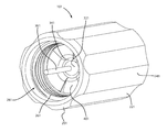
- FIG. 5 shows a perspective view of a CATV port terminator according to an embodiment of the invention.
- FIG. 6 shows a partially cutaway view of a CATV port terminator according to an embodiment of the invention.
- FIG. 7 shows an exploded view of a CATV port terminator according to an embodiment of the invention.
- FIG. 8 shows an exploded view of a CATV port terminator according to an embodiment of the invention.
- FIG. 9 shows a partially cutaway view of a CATV port terminator according to an embodiment of the invention.
- FIG. 10 shows a perspective view of a CATV port terminator according to an embodiment of the invention.
- FIG. 11 shows a perspective view of an example of an equipment port.
- a sealing element for a coaxial cable connector 100 ( FIGS. 3-4 ) is shown. More specifically, the sealing element is designed to ensure a solid mechanical and electrical connection between a coaxial cable, connector and part, and thereby termed a flexible radio frequency (“RF”) seal 10 .
- RF radio frequency
- Second, there is a transition band 14 and the band 14 transitions to a tubular insert portion 16 .
- the flexible RF seal 10 also has an insert chamber 18 defined within the seal 10 .
- the flexible brim 12 is a flange end that, when inserted into a coaxial cable connector, in its first embodiment, sits above a post member, as will be shown and described in greater detail below.
- the flexible brim 12 in this position, can be pressed against a coaxial port causing the flexible brim 12 to be compressed and bent so that it creates a tight connection between the connector and port.
- the flexible brim 12 because of the inner geometries of the coaxial cable connector, is angled, so that it can sit within the connector and seal the connector face to the cable port.
- the flexible brim 12 is seventy-degrees (70°) from the horizontal.
- the flexible brim 12 is shaped such that the flexible brim 12 is angled away from an insert chamber 18 .
- the next region of the flexible RF seal 10 is the transition band 14 .
- the transition band 14 Due to the shape of cable connectors in general and the positioning of the flexible RF seal within the connector, there is a band 14 that transitions the flexible brim 12 to the tubular insert portion 16 .
- the transition band 14 is a flat, inclined portion on the inside of the seal 10 .
- the transition band 14 assists in the flexibility of the seal 10 , in that as a transition portion it allows the flexible brim 12 to further bend or create a greater angle of distance once the flexible brim 12 is engaged by a coaxial port on one end and further compressed by a post member of a connector on its other end.
- the last region of the flexible RF seal is the tubular insert portion 16 .
- the tubular insert portion 16 is below the transition band 14 .
- the tubular insert portion 16 is cylindrical in shape and depending on its embodiment can be used to sit on the inside or outside of a post within a coaxial cable connector.
- Defined within the tubular insert portion 16 is an insert chamber 18 .
- the tubular insert portion 16 in the first embodiment of the flexible RF seal 10 , sits within a post member of a cable connector (as shown in FIG. 3 ). As a result, the insert chamber 18 assists in housing a coaxial cable on which the cable connector is placed.
- FIGS. 2A and 2B there is a second embodiment of the flexible RF seal, denoted by a reference numeral 20 .
- the flexible RF seal 20 has the same three regions as the first embodiment: a flexible brim 12 , a transition band 14 , and a tubular insert 16 . Further, defined within the flexible RF seal 20 , as with the first embodiment 10 , is an insert chamber 18 .
- the flexible RF seal 20 of this second embodiment has a different shape than the first embodiment 10 . The shapes are different because the seal 20 is configured to sit inside a post member instead of above the post member as is the case for the embodiment of FIGS. 1A-1B .
- the flexible brim 12 is spaced such that the brim 12 is angled inward towards the insert chamber 18 .
- the tubular insert 16 of the flexible RF seal 20 may generally be larger in diameter than the seal 10 because the tubular insert 16 is configured to sit outside of the post member of the coaxial cable connector.
- the flexible RF seal 10 , 20 can be made of any suitable material which can assist in providing a tight, solid physical and electrical connection between the surfaces of a coaxial cable connector and a cable port. Suitable materials can include metals such as beryllium copper, spring steel, and phosphor bronze, which are all resilient and allow for flexibility. Further, while the flexible RF seals 10 , 20 are shown in with a solid, smooth surface, the seal can have a construction where there are fingered elements, or may further have a wavy construction.
- FIGS. 3 and 4 there is shown a conventional coaxial cable connector 100 that is placed on the terminal end of a coaxial cable (not shown).
- the connector 100 has six elements. First, there is a nut 30 on the terminal end of the connector 100 to attach connector 100 , whose other end is attached to a coaxial cable (not shown), to a cable port (not shown).
- the nut 30 rotates freely around a post 40 , so that it can advance the connector 100 and coaxial cable housed within it to a cable port.
- the nut 30 is interconnected to the post 40 under the flange end 44 of the post 40 , whereby there is a nut groove 46 created between the post 40 and a body member 60 .
- the nut groove 46 is bounded by a flange end 44 of the post 40 and above an end of a body flange 62 .
- the corresponding nut flange 34 that fits within the nut groove 46 and allows the nut 20 to freely rotate about the connector 100 .
- the post 40 has a cylindrical bore defined through it to house portions of the coaxial cable.
- a coupling element 90 such as an O-ring to provide a weathertight connection between these elements.
- the body member 60 is also connected to the post 40 through a larger body groove 48 , in which a portion of the body flange 62 fits.
- a coaxial cable material space 80 defined between the body member 60 and the post 40 is a coaxial cable material space 80 .
- a coaxial cable is typically made from several components. Working from the inside to the outside, the inner most part of a cable is a central conductor surrounded by an inner dielectric layer which is covered by a layer of aluminum. Outside the aluminum layer is a braided metal layer, with the entire cable then housed in another dielectric material. There is a lower separator member 50 ( FIG.
- post 40 which separates the coaxial cable between its aluminum layer and braided metallic layer, so that the outer dielectric layer and braided metal layer enter the coaxial cable material space 80 , while the aluminum layer, inner dielectric layer, and central conductor layer sit in the cylindrical bore 82 of the post 40 .
- a compression ring 70 which assists in attaching the connector 100 to a prepared end of the coaxial cable.
- the post 40 has a lip 42 on which the flexible RF seal 10 sits.
- the tubular insert 16 sits within the post 40 , such that the insert chamber 18 assists in creating a continuous cylindrical bore within which a portion of a coaxial cable (not shown) would be housed.
- the flexible brim 12 sits above the flange end 44 of the post 40 , but is not flush with the flange end 44 .
- the flexible brim 12 is not flush with the flange end 44 so that it can conform to shapes of a cable port (not shown) and the connector 100 , and to a greater extent the cable housed within the connector, as sometimes there can be gaps between the cable port and the inner portions of the connector 100 with a cable.
- the flexible brim 12 can be, if necessary, pushed backward so that the angle from the horizontal increases from its manufactured positioning.
- the flexible brim 12 can be deformed to ensure an RF-tight connection between the post 40 and the cable port.
- the second embodiment of the seal 20 is shown coupled to connector 100 .
- the seal 20 sits on the outside of the flange end 44 of the post 40 .
- an end of tubular insert portion 16 abuts the seal 20 and the nut flange 34 , with a remainder of tubular insert portion 16 sandwiched between the flange end 44 of the post 40 and a portion of nut 30 .
- the flexible brim 12 extends past the flange end 44 , but is not flush with the flange end 44 so that it can adapt to the shape of both the cable port and the connector 100 with the coaxial cable housed within it.
- the post 40 does not require a lip 42 , as was shown in FIG. 3 with the seal 10 .
- a port terminator 101 is shown.
- a port terminator is fastened into an unused port of a device to provide an environmental seal to protect the inside components of the device and to provide an electrical “appearance” to the circuitry of the device that is neutral. That is to say, if the device expects to see a cable connector with 75 ohms of impedance at a given port, the port terminator provides the 75 ohms of impedance the device is looking for.
- an equipment port 2 which includes a connector end 4 , a conductor port 6 , and at least one thread 8 .
- Port terminator 101 includes an outer nut 201 which has a plurality of grooves 221 and ridges 241 to enhance contact between an installer's fingers (not shown) and port terminator 101 during installation and removal. At least one thread 261 on an inside of one end of outer nut 201 permits port terminator 101 to be screwed onto port 2 of a device (not shown).
- a termination resistor 321 which can be in the form of a peanut resistor, is positioned inside an insert chamber 403 and a nut chamber 281 of outer nut 201 as will be explained later.
- termination resistor 321 includes an insulator 341 surrounding an electrical resistance, a conductor portion 361 , and a ground portion 381 .
- Conductor portion 361 is designed to enter equipment port 2 and connect with the device (not shown) in the same manner as a center conductor of a coaxial cable (not shown).
- the electrical path runs from conductor port 6 to conductor portion 361 , through termination resistor 321 to ground portion 381 , to a ground insert 401 , and then to connector end 4 .
- Outer nut 201 is preferably made of injection molded plastic, and is preferably non-electrically conductive, but can optionally be made of an electrically conductive material in which case the use of ground insert 401 permits good port termination even if the outer nut is not screwed tightly onto equipment port 2 .
- Nut chamber 281 is cylindrical and contains at least one thread 261 therein, with a diameter sized to screw onto equipment port 2 .
- Insert chamber 403 is also cylindrical, but is of a smaller diameter than nut chamber 281 .
- Ground insert 401 is preferably press-fit into insert chamber 403 within outer nut 201 .
- Ground insert 401 is of an electrically conductive material, preferably metal, although other electrically conductive materials are known in the art.
- Ground insert 401 includes a capture portion 481 for capturing (receiving) and making good electrical contact with ground portion 381 of termination resistor 321 .
- An angled portion 425 frustoconical in shape, connects capture portion 481 with a middle portion 461 of ground insert 401 .
- Middle portion 461 is preferably sized so that its outer surface makes contact with the walls of insert chamber 403 , while its inner surface helps to hold termination resistor 321 in place.
- Termination resistor 321 is preferably connected to capture portion 481 of ground insert 401 in one of several ways to improve both the electrical connection and the physical connection.
- termination resistor 321 could be crimped into capture portion 481 , or it could be soldered.
- One method of connection would be to insert termination resistor 321 into capture portion 481 and then crimp capture portion 481 onto termination resistor 321 .
- Another method of connection would be to partially crimp capture portion 481 and then insert termination resistor 321 into capture portion 481 .
- Middle portion 461 of ground insert 401 connects to a plurality of flat petals 441 and biased petals 421 via a transition band 423 .
- Flat petals 441 are preferably alternated with biased petals 421 .
- petals 441 , 421 are preferably forced onto connector end 4 , and possibly onto thread 261 and/or a flat portion 283 of outer nut 201 which separates insert chamber 403 from nut chamber 281 .
- the partial deformation of petals 421 , 441 ensures excellent electrical contact between ground insert 401 and connector end 4 of equipment port 2 and provides enhanced RF shielding.
- ground insert 501 is shown which is similar to ground insert 401 except that instead of petals, a flexible brim 507 is used.
- Ground insert 501 fits into insert chamber 403 within outer nut 201 .
- Ground insert 501 is of an electrically conductive material, preferably metal, although other electrically materials are known in the art.
- Ground insert 501 includes a capture portion 505 for capturing (receiving) and making good electrical contact with ground portion 381 of termination resistor 321 .
- An angled portion 511 frustoconical in shape, connects capture portion 505 with a middle portion 503 of ground insert 501 .
- Middle portion 503 is preferably sized so that its outer surface makes electrical contact with the walls of insert chamber 403 , while its inner surface helps to hold termination resistor 321 in place.
- termination resistor 321 is preferably connected to capture portion 505 of ground insert 501 in one of several ways to improve both the electrical connection and the physical connection.
- termination resistor 321 could be crimped into capture portion 505 , or it could be soldered.
- One method of connection would be to insert termination resistor 321 into capture portion 505 and then crimp capture portion 505 onto termination resistor 321 .
- Another method of connection would be to partially crimp capture portion 505 and then insert termination resistor 321 into capture portion 505 .
- Middle portion 503 of ground insert 501 connects to flexible brim 507 via a transition band 509 .
- flexible brim 507 is preferably forced against connector end 4 , and possibly onto flat portion 283 of outer nut 201 which separates insert chamber 403 from nut chamber 281 .
- the partial deformation of flexible brim 507 ensures excellent electrical contact via rim 513 between ground insert 501 and connector end 4 and provides enhanced RF shielding.
- ground insert 401 and ground insert 501 are preferably formed using a progressive die process, with stamping in successive stages.
Abstract
Description
Claims (20)
Priority Applications (5)
| Application Number | Priority Date | Filing Date | Title |
|---|---|---|---|
| US12/835,128 US8062044B2 (en) | 2006-10-26 | 2010-07-13 | CATV port terminator with contact-enhancing ground insert |
| PCT/US2011/043559 WO2012009275A1 (en) | 2010-07-13 | 2011-07-11 | Catv port terminator with contact-enhancing ground insert |
| TW100124678A TW201223030A (en) | 2010-07-13 | 2011-07-12 | CATV port terminator with contact-enhancing ground insert |
| CN2011101957806A CN102332643A (en) | 2010-07-13 | 2011-07-13 | Flexible RF seal for coaxial cable connector |
| CN2011202464055U CN202363599U (en) | 2010-07-13 | 2011-07-13 | Port connector used for coaxial cable system |
Applications Claiming Priority (3)
| Application Number | Priority Date | Filing Date | Title |
|---|---|---|---|
| US11/553,115 US20080102696A1 (en) | 2006-10-26 | 2006-10-26 | Flexible rf seal for coax cable connector |
| US12/140,573 US7753705B2 (en) | 2006-10-26 | 2008-06-17 | Flexible RF seal for coaxial cable connector |
| US12/835,128 US8062044B2 (en) | 2006-10-26 | 2010-07-13 | CATV port terminator with contact-enhancing ground insert |
Related Parent Applications (1)
| Application Number | Title | Priority Date | Filing Date |
|---|---|---|---|
| US12/140,573 Continuation-In-Part US7753705B2 (en) | 2006-10-26 | 2008-06-17 | Flexible RF seal for coaxial cable connector |
Publications (2)
| Publication Number | Publication Date |
|---|---|
| US20100279548A1 US20100279548A1 (en) | 2010-11-04 |
| US8062044B2 true US8062044B2 (en) | 2011-11-22 |
Family
ID=44628678
Family Applications (1)
| Application Number | Title | Priority Date | Filing Date |
|---|---|---|---|
| US12/835,128 Active US8062044B2 (en) | 2006-10-26 | 2010-07-13 | CATV port terminator with contact-enhancing ground insert |
Country Status (4)
| Country | Link |
|---|---|
| US (1) | US8062044B2 (en) |
| CN (2) | CN102332643A (en) |
| TW (1) | TW201223030A (en) |
| WO (1) | WO2012009275A1 (en) |
Cited By (51)
| Publication number | Priority date | Publication date | Assignee | Title |
|---|---|---|---|---|
| US8147259B1 (en) * | 2010-11-02 | 2012-04-03 | Chun-Te Lee | Fixing device of anti-theft signal connector |
| US8172612B2 (en) | 2005-01-25 | 2012-05-08 | Corning Gilbert Inc. | Electrical connector with grounding member |
| US20120129387A1 (en) * | 2010-11-18 | 2012-05-24 | Michael Holland | Coaxial connector with enhanced shielding |
| US8192237B2 (en) | 2009-05-22 | 2012-06-05 | John Mezzalingua Associates, Inc. | Coaxial cable connector having electrical continuity member |
| US8272893B2 (en) | 2009-11-16 | 2012-09-25 | Corning Gilbert Inc. | Integrally conductive and shielded coaxial cable connector |
| US8287310B2 (en) | 2009-02-24 | 2012-10-16 | Corning Gilbert Inc. | Coaxial connector with dual-grip nut |
| US8323053B2 (en) | 2010-10-18 | 2012-12-04 | John Mezzalingua Associates, Inc. | Connector having a constant contact nut |
| US8337229B2 (en) | 2010-11-11 | 2012-12-25 | John Mezzalingua Associates, Inc. | Connector having a nut-body continuity element and method of use thereof |
| US8342879B2 (en) | 2011-03-25 | 2013-01-01 | John Mezzalingua Associates, Inc. | Coaxial cable connector |
| US8348697B2 (en) | 2011-04-22 | 2013-01-08 | John Mezzalingua Associates, Inc. | Coaxial cable connector having slotted post member |
| US8366481B2 (en) | 2011-03-30 | 2013-02-05 | John Mezzalingua Associates, Inc. | Continuity maintaining biasing member |
| US8382517B2 (en) | 2010-10-18 | 2013-02-26 | John Mezzalingua Associates, Inc. | Dielectric sealing member and method of use thereof |
| US8388377B2 (en) | 2011-04-01 | 2013-03-05 | John Mezzalingua Associates, Inc. | Slide actuated coaxial cable connector |
| US8398421B2 (en) | 2011-02-01 | 2013-03-19 | John Mezzalingua Associates, Inc. | Connector having a dielectric seal and method of use thereof |
| US8414322B2 (en) | 2010-12-14 | 2013-04-09 | Ppc Broadband, Inc. | Push-on CATV port terminator |
| US8444445B2 (en) | 2009-05-22 | 2013-05-21 | Ppc Broadband, Inc. | Coaxial cable connector having electrical continuity member |
| US8465322B2 (en) | 2011-03-25 | 2013-06-18 | Ppc Broadband, Inc. | Coaxial cable connector |
| US8469739B2 (en) | 2011-02-08 | 2013-06-25 | Belden Inc. | Cable connector with biasing element |
| US8506325B2 (en) | 2008-09-30 | 2013-08-13 | Belden Inc. | Cable connector having a biasing element |
| US8573996B2 (en) | 2009-05-22 | 2013-11-05 | Ppc Broadband, Inc. | Coaxial cable connector having electrical continuity member |
| US8591244B2 (en) | 2011-07-08 | 2013-11-26 | Ppc Broadband, Inc. | Cable connector |
| US8753147B2 (en) | 2011-06-10 | 2014-06-17 | Ppc Broadband, Inc. | Connector having a coupling member for locking onto a port and maintaining electrical continuity |
| US20140201987A1 (en) * | 2008-05-08 | 2014-07-24 | Pds Electronics, Inc. | Device for attaching a connector to a prepared coaxial cable |
| US8808019B2 (en) | 2010-11-01 | 2014-08-19 | Amphenol Corporation | Electrical connector with grounding member |
| US20140329411A1 (en) * | 2013-05-03 | 2014-11-06 | Ppc Broadband, Inc. | Interface terminating device |
| US8888526B2 (en) | 2010-08-10 | 2014-11-18 | Corning Gilbert, Inc. | Coaxial cable connector with radio frequency interference and grounding shield |
| US9017101B2 (en) | 2011-03-30 | 2015-04-28 | Ppc Broadband, Inc. | Continuity maintaining biasing member |
| US9048599B2 (en) | 2013-10-28 | 2015-06-02 | Corning Gilbert Inc. | Coaxial cable connector having a gripping member with a notch and disposed inside a shell |
| US9071019B2 (en) | 2010-10-27 | 2015-06-30 | Corning Gilbert, Inc. | Push-on cable connector with a coupler and retention and release mechanism |
| US9136654B2 (en) | 2012-01-05 | 2015-09-15 | Corning Gilbert, Inc. | Quick mount connector for a coaxial cable |
| US9147955B2 (en) | 2011-11-02 | 2015-09-29 | Ppc Broadband, Inc. | Continuity providing port |
| US9147963B2 (en) | 2012-11-29 | 2015-09-29 | Corning Gilbert Inc. | Hardline coaxial connector with a locking ferrule |
| US9153911B2 (en) | 2013-02-19 | 2015-10-06 | Corning Gilbert Inc. | Coaxial cable continuity connector |
| US9166348B2 (en) | 2010-04-13 | 2015-10-20 | Corning Gilbert Inc. | Coaxial connector with inhibited ingress and improved grounding |
| US9172154B2 (en) | 2013-03-15 | 2015-10-27 | Corning Gilbert Inc. | Coaxial cable connector with integral RFI protection |
| US9190744B2 (en) | 2011-09-14 | 2015-11-17 | Corning Optical Communications Rf Llc | Coaxial cable connector with radio frequency interference and grounding shield |
| US9203167B2 (en) | 2011-05-26 | 2015-12-01 | Ppc Broadband, Inc. | Coaxial cable connector with conductive seal |
| US9287659B2 (en) | 2012-10-16 | 2016-03-15 | Corning Optical Communications Rf Llc | Coaxial cable connector with integral RFI protection |
| US9407016B2 (en) | 2012-02-22 | 2016-08-02 | Corning Optical Communications Rf Llc | Coaxial cable connector with integral continuity contacting portion |
| US9525220B1 (en) | 2015-11-25 | 2016-12-20 | Corning Optical Communications LLC | Coaxial cable connector |
| US9548557B2 (en) | 2013-06-26 | 2017-01-17 | Corning Optical Communications LLC | Connector assemblies and methods of manufacture |
| US9548572B2 (en) | 2014-11-03 | 2017-01-17 | Corning Optical Communications LLC | Coaxial cable connector having a coupler and a post with a contacting portion and a shoulder |
| US9570845B2 (en) | 2009-05-22 | 2017-02-14 | Ppc Broadband, Inc. | Connector having a continuity member operable in a radial direction |
| US9590287B2 (en) | 2015-02-20 | 2017-03-07 | Corning Optical Communications Rf Llc | Surge protected coaxial termination |
| US9711917B2 (en) | 2011-05-26 | 2017-07-18 | Ppc Broadband, Inc. | Band spring continuity member for coaxial cable connector |
| US9762008B2 (en) | 2013-05-20 | 2017-09-12 | Corning Optical Communications Rf Llc | Coaxial cable connector with integral RFI protection |
| US9859631B2 (en) | 2011-09-15 | 2018-01-02 | Corning Optical Communications Rf Llc | Coaxial cable connector with integral radio frequency interference and grounding shield |
| US10033122B2 (en) | 2015-02-20 | 2018-07-24 | Corning Optical Communications Rf Llc | Cable or conduit connector with jacket retention feature |
| US10211547B2 (en) | 2015-09-03 | 2019-02-19 | Corning Optical Communications Rf Llc | Coaxial cable connector |
| US10290958B2 (en) | 2013-04-29 | 2019-05-14 | Corning Optical Communications Rf Llc | Coaxial cable connector with integral RFI protection and biasing ring |
| US11512798B2 (en) | 2018-11-05 | 2022-11-29 | Swagelok Company | Mechanically locking end screw arrangements |
Families Citing this family (8)
| Publication number | Priority date | Publication date | Assignee | Title |
|---|---|---|---|---|
| US8157589B2 (en) | 2004-11-24 | 2012-04-17 | John Mezzalingua Associates, Inc. | Connector having a conductively coated member and method of use thereof |
| US8062044B2 (en) * | 2006-10-26 | 2011-11-22 | John Mezzalingua Associates, Inc. | CATV port terminator with contact-enhancing ground insert |
| US7824216B2 (en) | 2009-04-02 | 2010-11-02 | John Mezzalingua Associates, Inc. | Coaxial cable continuity connector |
| US8079860B1 (en) | 2010-07-22 | 2011-12-20 | John Mezzalingua Associates, Inc. | Cable connector having threaded locking collet and nut |
| US8152551B2 (en) | 2010-07-22 | 2012-04-10 | John Mezzalingua Associates, Inc. | Port seizing cable connector nut and assembly |
| US8167636B1 (en) | 2010-10-15 | 2012-05-01 | John Mezzalingua Associates, Inc. | Connector having a continuity member |
| US8167646B1 (en) | 2010-10-18 | 2012-05-01 | John Mezzalingua Associates, Inc. | Connector having electrical continuity about an inner dielectric and method of use thereof |
| WO2014172554A1 (en) | 2013-04-17 | 2014-10-23 | Ppc Broadband, Inc. | Post assembly for coaxial cable connectors |
Citations (47)
| Publication number | Priority date | Publication date | Assignee | Title |
|---|---|---|---|---|
| US3184706A (en) | 1962-09-27 | 1965-05-18 | Itt | Coaxial cable connector with internal crimping structure |
| US3321732A (en) * | 1965-05-14 | 1967-05-23 | Amp Inc | Crimp type coaxial connector assembly |
| US3336563A (en) | 1964-04-13 | 1967-08-15 | Amphenol Corp | Coaxial connectors |
| US3448430A (en) * | 1967-01-23 | 1969-06-03 | Thomas & Betts Corp | Ground connector |
| US3537065A (en) | 1967-01-12 | 1970-10-27 | Jerrold Electronics Corp | Multiferrule cable connector |
| US3646502A (en) | 1970-08-24 | 1972-02-29 | Bunker Ramo | Connector element and method for element assembly |
| US3706958A (en) | 1970-10-28 | 1972-12-19 | Itt | Coaxial cable connector |
| US3744011A (en) | 1971-10-28 | 1973-07-03 | Itt | Coaxial cable connector |
| US3781762A (en) | 1972-06-26 | 1973-12-25 | Tidal Sales Corp | Connector assembly |
| US4173385A (en) | 1978-04-20 | 1979-11-06 | Bunker Ramo Corporation | Watertight cable connector |
| US4290663A (en) | 1979-10-23 | 1981-09-22 | United Kingdom Atomic Energy Authority | In high frequency screening of electrical systems |
| US4469386A (en) * | 1981-09-23 | 1984-09-04 | Viewsonics, Inc. | Tamper-resistant terminator for a female coaxial plug |
| US4531805A (en) * | 1984-04-03 | 1985-07-30 | Allied Corporation | Electrical connector assembly having means for EMI shielding |
| US4655534A (en) * | 1985-03-15 | 1987-04-07 | E. F. Johnson Company | Right angle coaxial connector |
| US4807891A (en) * | 1987-07-06 | 1989-02-28 | The United States Of America As Represented By The Secretary Of The Air Force | Electromagnetic pulse rotary seal |
| US5011422A (en) * | 1990-08-13 | 1991-04-30 | Yeh Ming Hwa | Coaxial cable output terminal safety plug device |
| US5046964A (en) * | 1989-10-10 | 1991-09-10 | Itt Corporation | Hybrid connector |
| US5052947A (en) * | 1990-11-26 | 1991-10-01 | United States Of America As Represented By The Secretary Of The Air Force | Cable shield termination backshell |
| US5055060A (en) * | 1989-06-02 | 1991-10-08 | Gilbert Engineering Company, Inc. | Tamper-resistant cable terminator system |
| US5137471A (en) | 1990-07-06 | 1992-08-11 | Amphenol Corporation | Modular plug connector and method of assembly |
| US5183417A (en) * | 1991-12-11 | 1993-02-02 | General Electric Company | Cable backshell |
| US5389005A (en) | 1993-06-22 | 1995-02-14 | Yazaki Corporation | Waterproof electric connector seal member |
| US5735704A (en) * | 1995-05-17 | 1998-04-07 | Hubbell Incorporated | Shroud seal for shrouded electrical connector |
| US6331123B1 (en) | 2000-11-20 | 2001-12-18 | Thomas & Betts International, Inc. | Connector for hard-line coaxial cable |
| US20020013088A1 (en) | 2000-05-10 | 2002-01-31 | Thomas & Betts International, Inc. | Coaxial connector having detachable locking sleeve |
| US6406330B2 (en) * | 1999-12-10 | 2002-06-18 | Northrop Grumman Corporation | Clip ring for an electrical connector |
| US6491546B1 (en) * | 2000-03-07 | 2002-12-10 | John Mezzalingua Associates, Inc. | Locking F terminator for coaxial cable systems |
| US6716062B1 (en) | 2002-10-21 | 2004-04-06 | John Mezzalingua Associates, Inc. | Coaxial cable F connector with improved RFI sealing |
| US6733336B1 (en) * | 2003-04-03 | 2004-05-11 | John Mezzalingua Associates, Inc. | Compression-type hard-line connector |
| US6884113B1 (en) * | 2003-10-15 | 2005-04-26 | John Mezzalingua Associates, Inc. | Apparatus for making permanent hardline connection |
| US20050148236A1 (en) | 1997-08-02 | 2005-07-07 | Montena Noah P. | Connector and method of operation |
| US6929508B1 (en) | 2004-03-30 | 2005-08-16 | Michael Holland | Coaxial cable connector with viewing window |
| US20060009074A1 (en) | 2003-07-21 | 2006-01-12 | John Mezzalingua Associates, Inc. | Environmentally protected and tamper resistant CATV drop connector |
| US20060110977A1 (en) | 2004-11-24 | 2006-05-25 | Roger Matthews | Connector having conductive member and method of use thereof |
| US7070477B2 (en) | 2004-04-30 | 2006-07-04 | Hitachi, Ltd. | Method of polishing semiconductor wafer |
| US20060172571A1 (en) | 2004-07-16 | 2006-08-03 | John Mezzalingua Associates, Inc. | Compression connector for coaxial cable |
| US7086897B2 (en) * | 2004-11-18 | 2006-08-08 | John Mezzalingua Associates, Inc. | Compression connector and method of use |
| US7097499B1 (en) * | 2005-08-18 | 2006-08-29 | John Mezzalingua Associates, Inc. | Coaxial cable connector having conductive engagement element and method of use thereof |
| US7102868B2 (en) * | 2000-11-30 | 2006-09-05 | John Mezzalingua Associates, Inc. | High voltage surge protection element for use with CATV coaxial cable connectors |
| US7114990B2 (en) * | 2005-01-25 | 2006-10-03 | Corning Gilbert Incorporated | Coaxial cable connector with grounding member |
| US7156696B1 (en) | 2006-07-19 | 2007-01-02 | John Mezzalingua Associates, Inc. | Connector for corrugated coaxial cable and method |
| US7161785B2 (en) * | 2000-11-30 | 2007-01-09 | John Mezzalingua Associates, Inc. | Apparatus for high surge voltage protection |
| US20080102696A1 (en) * | 2006-10-26 | 2008-05-01 | John Mezzalingua Associates, Inc. | Flexible rf seal for coax cable connector |
| US7452239B2 (en) * | 2006-10-26 | 2008-11-18 | John Mezzalingua Associates Inc. | Coax cable port locking terminator device |
| US7824216B2 (en) * | 2009-04-02 | 2010-11-02 | John Mezzalingua Associates, Inc. | Coaxial cable continuity connector |
| US20100279548A1 (en) * | 2006-10-26 | 2010-11-04 | Noah Montena | CATV Port Terminator With Contact-Enhancing Ground Insert |
| US7892005B2 (en) * | 2009-05-19 | 2011-02-22 | John Mezzalingua Associates, Inc. | Click-tight coaxial cable continuity connector |
Family Cites Families (3)
| Publication number | Priority date | Publication date | Assignee | Title |
|---|---|---|---|---|
| US4838813A (en) * | 1988-05-10 | 1989-06-13 | Amp Incorporated | Terminator plug with electrical resistor |
| CN201207525Y (en) * | 2008-06-04 | 2009-03-11 | 富士康(昆山)电脑接插件有限公司 | RF coaxial connector |
| US8231406B2 (en) * | 2008-10-29 | 2012-07-31 | Corning Gilbert Inc. | RF terminator with improved electrical circuit |
-
2010
- 2010-07-13 US US12/835,128 patent/US8062044B2/en active Active
-
2011
- 2011-07-11 WO PCT/US2011/043559 patent/WO2012009275A1/en active Application Filing
- 2011-07-12 TW TW100124678A patent/TW201223030A/en unknown
- 2011-07-13 CN CN2011101957806A patent/CN102332643A/en active Pending
- 2011-07-13 CN CN2011202464055U patent/CN202363599U/en not_active Expired - Fee Related
Patent Citations (51)
| Publication number | Priority date | Publication date | Assignee | Title |
|---|---|---|---|---|
| US3184706A (en) | 1962-09-27 | 1965-05-18 | Itt | Coaxial cable connector with internal crimping structure |
| US3336563A (en) | 1964-04-13 | 1967-08-15 | Amphenol Corp | Coaxial connectors |
| US3321732A (en) * | 1965-05-14 | 1967-05-23 | Amp Inc | Crimp type coaxial connector assembly |
| US3537065A (en) | 1967-01-12 | 1970-10-27 | Jerrold Electronics Corp | Multiferrule cable connector |
| US3448430A (en) * | 1967-01-23 | 1969-06-03 | Thomas & Betts Corp | Ground connector |
| US3646502A (en) | 1970-08-24 | 1972-02-29 | Bunker Ramo | Connector element and method for element assembly |
| US3706958A (en) | 1970-10-28 | 1972-12-19 | Itt | Coaxial cable connector |
| US3744011A (en) | 1971-10-28 | 1973-07-03 | Itt | Coaxial cable connector |
| US3781762A (en) | 1972-06-26 | 1973-12-25 | Tidal Sales Corp | Connector assembly |
| US4173385A (en) | 1978-04-20 | 1979-11-06 | Bunker Ramo Corporation | Watertight cable connector |
| US4290663A (en) | 1979-10-23 | 1981-09-22 | United Kingdom Atomic Energy Authority | In high frequency screening of electrical systems |
| US4469386A (en) * | 1981-09-23 | 1984-09-04 | Viewsonics, Inc. | Tamper-resistant terminator for a female coaxial plug |
| US4531805A (en) * | 1984-04-03 | 1985-07-30 | Allied Corporation | Electrical connector assembly having means for EMI shielding |
| US4655534A (en) * | 1985-03-15 | 1987-04-07 | E. F. Johnson Company | Right angle coaxial connector |
| US4807891A (en) * | 1987-07-06 | 1989-02-28 | The United States Of America As Represented By The Secretary Of The Air Force | Electromagnetic pulse rotary seal |
| US5055060A (en) * | 1989-06-02 | 1991-10-08 | Gilbert Engineering Company, Inc. | Tamper-resistant cable terminator system |
| US5046964A (en) * | 1989-10-10 | 1991-09-10 | Itt Corporation | Hybrid connector |
| US5137471A (en) | 1990-07-06 | 1992-08-11 | Amphenol Corporation | Modular plug connector and method of assembly |
| US5011422A (en) * | 1990-08-13 | 1991-04-30 | Yeh Ming Hwa | Coaxial cable output terminal safety plug device |
| US5052947A (en) * | 1990-11-26 | 1991-10-01 | United States Of America As Represented By The Secretary Of The Air Force | Cable shield termination backshell |
| US5183417A (en) * | 1991-12-11 | 1993-02-02 | General Electric Company | Cable backshell |
| US5389005A (en) | 1993-06-22 | 1995-02-14 | Yazaki Corporation | Waterproof electric connector seal member |
| US5735704A (en) * | 1995-05-17 | 1998-04-07 | Hubbell Incorporated | Shroud seal for shrouded electrical connector |
| US20050148236A1 (en) | 1997-08-02 | 2005-07-07 | Montena Noah P. | Connector and method of operation |
| US6406330B2 (en) * | 1999-12-10 | 2002-06-18 | Northrop Grumman Corporation | Clip ring for an electrical connector |
| US6491546B1 (en) * | 2000-03-07 | 2002-12-10 | John Mezzalingua Associates, Inc. | Locking F terminator for coaxial cable systems |
| US20020013088A1 (en) | 2000-05-10 | 2002-01-31 | Thomas & Betts International, Inc. | Coaxial connector having detachable locking sleeve |
| US6331123B1 (en) | 2000-11-20 | 2001-12-18 | Thomas & Betts International, Inc. | Connector for hard-line coaxial cable |
| US7161785B2 (en) * | 2000-11-30 | 2007-01-09 | John Mezzalingua Associates, Inc. | Apparatus for high surge voltage protection |
| US7102868B2 (en) * | 2000-11-30 | 2006-09-05 | John Mezzalingua Associates, Inc. | High voltage surge protection element for use with CATV coaxial cable connectors |
| US6716062B1 (en) | 2002-10-21 | 2004-04-06 | John Mezzalingua Associates, Inc. | Coaxial cable F connector with improved RFI sealing |
| US6733336B1 (en) * | 2003-04-03 | 2004-05-11 | John Mezzalingua Associates, Inc. | Compression-type hard-line connector |
| US20060009074A1 (en) | 2003-07-21 | 2006-01-12 | John Mezzalingua Associates, Inc. | Environmentally protected and tamper resistant CATV drop connector |
| US7299550B2 (en) | 2003-07-21 | 2007-11-27 | John Mezzalingua Associates, Inc. | Environmentally protected and tamper resistant CATV drop connector |
| US6884113B1 (en) * | 2003-10-15 | 2005-04-26 | John Mezzalingua Associates, Inc. | Apparatus for making permanent hardline connection |
| US6929508B1 (en) | 2004-03-30 | 2005-08-16 | Michael Holland | Coaxial cable connector with viewing window |
| US7070477B2 (en) | 2004-04-30 | 2006-07-04 | Hitachi, Ltd. | Method of polishing semiconductor wafer |
| US7131868B2 (en) | 2004-07-16 | 2006-11-07 | John Mezzalingua Associates, Inc. | Compression connector for coaxial cable |
| US20060172571A1 (en) | 2004-07-16 | 2006-08-03 | John Mezzalingua Associates, Inc. | Compression connector for coaxial cable |
| US7086897B2 (en) * | 2004-11-18 | 2006-08-08 | John Mezzalingua Associates, Inc. | Compression connector and method of use |
| US20060110977A1 (en) | 2004-11-24 | 2006-05-25 | Roger Matthews | Connector having conductive member and method of use thereof |
| US7114990B2 (en) * | 2005-01-25 | 2006-10-03 | Corning Gilbert Incorporated | Coaxial cable connector with grounding member |
| US7479035B2 (en) * | 2005-01-25 | 2009-01-20 | Corning Gilbert Inc. | Electrical connector with grounding member |
| US7097499B1 (en) * | 2005-08-18 | 2006-08-29 | John Mezzalingua Associates, Inc. | Coaxial cable connector having conductive engagement element and method of use thereof |
| US7156696B1 (en) | 2006-07-19 | 2007-01-02 | John Mezzalingua Associates, Inc. | Connector for corrugated coaxial cable and method |
| US20080102696A1 (en) * | 2006-10-26 | 2008-05-01 | John Mezzalingua Associates, Inc. | Flexible rf seal for coax cable connector |
| US7452239B2 (en) * | 2006-10-26 | 2008-11-18 | John Mezzalingua Associates Inc. | Coax cable port locking terminator device |
| US7753705B2 (en) * | 2006-10-26 | 2010-07-13 | John Mezzalingua Assoc., Inc. | Flexible RF seal for coaxial cable connector |
| US20100279548A1 (en) * | 2006-10-26 | 2010-11-04 | Noah Montena | CATV Port Terminator With Contact-Enhancing Ground Insert |
| US7824216B2 (en) * | 2009-04-02 | 2010-11-02 | John Mezzalingua Associates, Inc. | Coaxial cable continuity connector |
| US7892005B2 (en) * | 2009-05-19 | 2011-02-22 | John Mezzalingua Associates, Inc. | Click-tight coaxial cable continuity connector |
Cited By (106)
| Publication number | Priority date | Publication date | Assignee | Title |
|---|---|---|---|---|
| US8172612B2 (en) | 2005-01-25 | 2012-05-08 | Corning Gilbert Inc. | Electrical connector with grounding member |
| US8690603B2 (en) | 2005-01-25 | 2014-04-08 | Corning Gilbert Inc. | Electrical connector with grounding member |
| US10756455B2 (en) | 2005-01-25 | 2020-08-25 | Corning Optical Communications Rf Llc | Electrical connector with grounding member |
| US9614341B2 (en) * | 2008-05-08 | 2017-04-04 | Pds Electronics, Inc. | Device for attaching a connector to a prepared coaxial cable |
| US20140201987A1 (en) * | 2008-05-08 | 2014-07-24 | Pds Electronics, Inc. | Device for attaching a connector to a prepared coaxial cable |
| US8506325B2 (en) | 2008-09-30 | 2013-08-13 | Belden Inc. | Cable connector having a biasing element |
| US8287310B2 (en) | 2009-02-24 | 2012-10-16 | Corning Gilbert Inc. | Coaxial connector with dual-grip nut |
| US8597041B2 (en) | 2009-05-22 | 2013-12-03 | Ppc Broadband, Inc. | Coaxial cable connector having electrical continuity member |
| US9570845B2 (en) | 2009-05-22 | 2017-02-14 | Ppc Broadband, Inc. | Connector having a continuity member operable in a radial direction |
| US8323060B2 (en) | 2009-05-22 | 2012-12-04 | John Mezzalingua Associates, Inc. | Coaxial cable connector having electrical continuity member |
| US8801448B2 (en) | 2009-05-22 | 2014-08-12 | Ppc Broadband, Inc. | Coaxial cable connector having electrical continuity structure |
| US8192237B2 (en) | 2009-05-22 | 2012-06-05 | John Mezzalingua Associates, Inc. | Coaxial cable connector having electrical continuity member |
| US9660398B2 (en) | 2009-05-22 | 2017-05-23 | Ppc Broadband, Inc. | Coaxial cable connector having electrical continuity member |
| US8313353B2 (en) | 2009-05-22 | 2012-11-20 | John Mezzalingua Associates, Inc. | Coaxial cable connector having electrical continuity member |
| US8647136B2 (en) | 2009-05-22 | 2014-02-11 | Ppc Broadband, Inc. | Coaxial cable connector having electrical continuity member |
| US8573996B2 (en) | 2009-05-22 | 2013-11-05 | Ppc Broadband, Inc. | Coaxial cable connector having electrical continuity member |
| US10931068B2 (en) | 2009-05-22 | 2021-02-23 | Ppc Broadband, Inc. | Connector having a grounding member operable in a radial direction |
| US8562366B2 (en) | 2009-05-22 | 2013-10-22 | Ppc Broadband, Inc. | Coaxial cable connector having electrical continuity member |
| US9496661B2 (en) | 2009-05-22 | 2016-11-15 | Ppc Broadband, Inc. | Coaxial cable connector having electrical continuity member |
| US8444445B2 (en) | 2009-05-22 | 2013-05-21 | Ppc Broadband, Inc. | Coaxial cable connector having electrical continuity member |
| US10862251B2 (en) | 2009-05-22 | 2020-12-08 | Ppc Broadband, Inc. | Coaxial cable connector having an electrical grounding portion |
| US9419389B2 (en) | 2009-05-22 | 2016-08-16 | Ppc Broadband, Inc. | Coaxial cable connector having electrical continuity member |
| US8287320B2 (en) | 2009-05-22 | 2012-10-16 | John Mezzalingua Associates, Inc. | Coaxial cable connector having electrical continuity member |
| US8272893B2 (en) | 2009-11-16 | 2012-09-25 | Corning Gilbert Inc. | Integrally conductive and shielded coaxial cable connector |
| US10312629B2 (en) | 2010-04-13 | 2019-06-04 | Corning Optical Communications Rf Llc | Coaxial connector with inhibited ingress and improved grounding |
| US9905959B2 (en) | 2010-04-13 | 2018-02-27 | Corning Optical Communication RF LLC | Coaxial connector with inhibited ingress and improved grounding |
| US9166348B2 (en) | 2010-04-13 | 2015-10-20 | Corning Gilbert Inc. | Coaxial connector with inhibited ingress and improved grounding |
| US8888526B2 (en) | 2010-08-10 | 2014-11-18 | Corning Gilbert, Inc. | Coaxial cable connector with radio frequency interference and grounding shield |
| US8323053B2 (en) | 2010-10-18 | 2012-12-04 | John Mezzalingua Associates, Inc. | Connector having a constant contact nut |
| US8382517B2 (en) | 2010-10-18 | 2013-02-26 | John Mezzalingua Associates, Inc. | Dielectric sealing member and method of use thereof |
| US9071019B2 (en) | 2010-10-27 | 2015-06-30 | Corning Gilbert, Inc. | Push-on cable connector with a coupler and retention and release mechanism |
| US8808019B2 (en) | 2010-11-01 | 2014-08-19 | Amphenol Corporation | Electrical connector with grounding member |
| US8147259B1 (en) * | 2010-11-02 | 2012-04-03 | Chun-Te Lee | Fixing device of anti-theft signal connector |
| US8550835B2 (en) | 2010-11-11 | 2013-10-08 | Ppc Broadband, Inc. | Connector having a nut-body continuity element and method of use thereof |
| US8529279B2 (en) | 2010-11-11 | 2013-09-10 | Ppc Broadband, Inc. | Connector having a nut-body continuity element and method of use thereof |
| US8920192B2 (en) | 2010-11-11 | 2014-12-30 | Ppc Broadband, Inc. | Connector having a coupler-body continuity member |
| US8920182B2 (en) | 2010-11-11 | 2014-12-30 | Ppc Broadband, Inc. | Connector having a coupler-body continuity member |
| US8337229B2 (en) | 2010-11-11 | 2012-12-25 | John Mezzalingua Associates, Inc. | Connector having a nut-body continuity element and method of use thereof |
| US10686264B2 (en) | 2010-11-11 | 2020-06-16 | Ppc Broadband, Inc. | Coaxial cable connector having a grounding bridge portion |
| US8858251B2 (en) | 2010-11-11 | 2014-10-14 | Ppc Broadband, Inc. | Connector having a coupler-body continuity member |
| US8915754B2 (en) | 2010-11-11 | 2014-12-23 | Ppc Broadband, Inc. | Connector having a coupler-body continuity member |
| US8376769B2 (en) * | 2010-11-18 | 2013-02-19 | Holland Electronics, Llc | Coaxial connector with enhanced shielding |
| US8727800B2 (en) | 2010-11-18 | 2014-05-20 | Holland Electronics, Llc | Coaxial connector with enhanced shielding |
| US20120129387A1 (en) * | 2010-11-18 | 2012-05-24 | Michael Holland | Coaxial connector with enhanced shielding |
| US8414322B2 (en) | 2010-12-14 | 2013-04-09 | Ppc Broadband, Inc. | Push-on CATV port terminator |
| US8398421B2 (en) | 2011-02-01 | 2013-03-19 | John Mezzalingua Associates, Inc. | Connector having a dielectric seal and method of use thereof |
| US8469739B2 (en) | 2011-02-08 | 2013-06-25 | Belden Inc. | Cable connector with biasing element |
| US9153917B2 (en) | 2011-03-25 | 2015-10-06 | Ppc Broadband, Inc. | Coaxial cable connector |
| US8342879B2 (en) | 2011-03-25 | 2013-01-01 | John Mezzalingua Associates, Inc. | Coaxial cable connector |
| US8465322B2 (en) | 2011-03-25 | 2013-06-18 | Ppc Broadband, Inc. | Coaxial cable connector |
| US8480431B2 (en) | 2011-03-30 | 2013-07-09 | Ppc Broadband, Inc. | Continuity maintaining biasing member |
| US8475205B2 (en) | 2011-03-30 | 2013-07-02 | Ppc Broadband, Inc. | Continuity maintaining biasing member |
| US9608345B2 (en) | 2011-03-30 | 2017-03-28 | Ppc Broadband, Inc. | Continuity maintaining biasing member |
| US9595776B2 (en) | 2011-03-30 | 2017-03-14 | Ppc Broadband, Inc. | Connector producing a biasing force |
| US8366481B2 (en) | 2011-03-30 | 2013-02-05 | John Mezzalingua Associates, Inc. | Continuity maintaining biasing member |
| US10559898B2 (en) | 2011-03-30 | 2020-02-11 | Ppc Broadband, Inc. | Connector producing a biasing force |
| US8480430B2 (en) | 2011-03-30 | 2013-07-09 | Ppc Broadband, Inc. | Continuity maintaining biasing member |
| US8485845B2 (en) | 2011-03-30 | 2013-07-16 | Ppc Broadband, Inc. | Continuity maintaining biasing member |
| US9660360B2 (en) | 2011-03-30 | 2017-05-23 | Ppc Broadband, Inc. | Connector producing a biasing force |
| US10186790B2 (en) | 2011-03-30 | 2019-01-22 | Ppc Broadband, Inc. | Connector producing a biasing force |
| US8469740B2 (en) | 2011-03-30 | 2013-06-25 | Ppc Broadband, Inc. | Continuity maintaining biasing member |
| US11811184B2 (en) | 2011-03-30 | 2023-11-07 | Ppc Broadband, Inc. | Connector producing a biasing force |
| US9017101B2 (en) | 2011-03-30 | 2015-04-28 | Ppc Broadband, Inc. | Continuity maintaining biasing member |
| US8388377B2 (en) | 2011-04-01 | 2013-03-05 | John Mezzalingua Associates, Inc. | Slide actuated coaxial cable connector |
| US8348697B2 (en) | 2011-04-22 | 2013-01-08 | John Mezzalingua Associates, Inc. | Coaxial cable connector having slotted post member |
| US10707629B2 (en) | 2011-05-26 | 2020-07-07 | Ppc Broadband, Inc. | Grounding member for coaxial cable connector |
| US11283226B2 (en) | 2011-05-26 | 2022-03-22 | Ppc Broadband, Inc. | Grounding member for coaxial cable connector |
| US9711917B2 (en) | 2011-05-26 | 2017-07-18 | Ppc Broadband, Inc. | Band spring continuity member for coaxial cable connector |
| US9203167B2 (en) | 2011-05-26 | 2015-12-01 | Ppc Broadband, Inc. | Coaxial cable connector with conductive seal |
| US8753147B2 (en) | 2011-06-10 | 2014-06-17 | Ppc Broadband, Inc. | Connector having a coupling member for locking onto a port and maintaining electrical continuity |
| US8758050B2 (en) | 2011-06-10 | 2014-06-24 | Hiscock & Barclay LLP | Connector having a coupling member for locking onto a port and maintaining electrical continuity |
| US8591244B2 (en) | 2011-07-08 | 2013-11-26 | Ppc Broadband, Inc. | Cable connector |
| US9190744B2 (en) | 2011-09-14 | 2015-11-17 | Corning Optical Communications Rf Llc | Coaxial cable connector with radio frequency interference and grounding shield |
| US9859631B2 (en) | 2011-09-15 | 2018-01-02 | Corning Optical Communications Rf Llc | Coaxial cable connector with integral radio frequency interference and grounding shield |
| US10700475B2 (en) | 2011-11-02 | 2020-06-30 | Ppc Broadband, Inc. | Devices for biasingly maintaining a port ground path |
| US10116099B2 (en) | 2011-11-02 | 2018-10-30 | Ppc Broadband, Inc. | Devices for biasingly maintaining a port ground path |
| US11233362B2 (en) | 2011-11-02 | 2022-01-25 | Ppc Broadband, Inc. | Devices for biasingly maintaining a port ground path |
| US9147955B2 (en) | 2011-11-02 | 2015-09-29 | Ppc Broadband, Inc. | Continuity providing port |
| US9537232B2 (en) | 2011-11-02 | 2017-01-03 | Ppc Broadband, Inc. | Continuity providing port |
| US9136654B2 (en) | 2012-01-05 | 2015-09-15 | Corning Gilbert, Inc. | Quick mount connector for a coaxial cable |
| US9768565B2 (en) | 2012-01-05 | 2017-09-19 | Corning Optical Communications Rf Llc | Quick mount connector for a coaxial cable |
| US9484645B2 (en) | 2012-01-05 | 2016-11-01 | Corning Optical Communications Rf Llc | Quick mount connector for a coaxial cable |
| US9407016B2 (en) | 2012-02-22 | 2016-08-02 | Corning Optical Communications Rf Llc | Coaxial cable connector with integral continuity contacting portion |
| US10236636B2 (en) | 2012-10-16 | 2019-03-19 | Corning Optical Communications Rf Llc | Coaxial cable connector with integral RFI protection |
| US9722363B2 (en) | 2012-10-16 | 2017-08-01 | Corning Optical Communications Rf Llc | Coaxial cable connector with integral RFI protection |
| US9912105B2 (en) | 2012-10-16 | 2018-03-06 | Corning Optical Communications Rf Llc | Coaxial cable connector with integral RFI protection |
| US9287659B2 (en) | 2012-10-16 | 2016-03-15 | Corning Optical Communications Rf Llc | Coaxial cable connector with integral RFI protection |
| US9147963B2 (en) | 2012-11-29 | 2015-09-29 | Corning Gilbert Inc. | Hardline coaxial connector with a locking ferrule |
| US9153911B2 (en) | 2013-02-19 | 2015-10-06 | Corning Gilbert Inc. | Coaxial cable continuity connector |
| US9172154B2 (en) | 2013-03-15 | 2015-10-27 | Corning Gilbert Inc. | Coaxial cable connector with integral RFI protection |
| US10290958B2 (en) | 2013-04-29 | 2019-05-14 | Corning Optical Communications Rf Llc | Coaxial cable connector with integral RFI protection and biasing ring |
| US9362686B2 (en) * | 2013-05-03 | 2016-06-07 | Ppc Broadband, Inc. | Interface terminating device |
| US10148243B2 (en) | 2013-05-03 | 2018-12-04 | Ppc Broadband, Inc. | Interface terminating device |
| US20140329411A1 (en) * | 2013-05-03 | 2014-11-06 | Ppc Broadband, Inc. | Interface terminating device |
| US10396508B2 (en) | 2013-05-20 | 2019-08-27 | Corning Optical Communications Rf Llc | Coaxial cable connector with integral RFI protection |
| US9762008B2 (en) | 2013-05-20 | 2017-09-12 | Corning Optical Communications Rf Llc | Coaxial cable connector with integral RFI protection |
| US9548557B2 (en) | 2013-06-26 | 2017-01-17 | Corning Optical Communications LLC | Connector assemblies and methods of manufacture |
| US9048599B2 (en) | 2013-10-28 | 2015-06-02 | Corning Gilbert Inc. | Coaxial cable connector having a gripping member with a notch and disposed inside a shell |
| US9548572B2 (en) | 2014-11-03 | 2017-01-17 | Corning Optical Communications LLC | Coaxial cable connector having a coupler and a post with a contacting portion and a shoulder |
| US9991651B2 (en) | 2014-11-03 | 2018-06-05 | Corning Optical Communications Rf Llc | Coaxial cable connector with post including radially expanding tabs |
| US9590287B2 (en) | 2015-02-20 | 2017-03-07 | Corning Optical Communications Rf Llc | Surge protected coaxial termination |
| US10033122B2 (en) | 2015-02-20 | 2018-07-24 | Corning Optical Communications Rf Llc | Cable or conduit connector with jacket retention feature |
| US10211547B2 (en) | 2015-09-03 | 2019-02-19 | Corning Optical Communications Rf Llc | Coaxial cable connector |
| US9525220B1 (en) | 2015-11-25 | 2016-12-20 | Corning Optical Communications LLC | Coaxial cable connector |
| US9882320B2 (en) | 2015-11-25 | 2018-01-30 | Corning Optical Communications Rf Llc | Coaxial cable connector |
| US11512798B2 (en) | 2018-11-05 | 2022-11-29 | Swagelok Company | Mechanically locking end screw arrangements |
Also Published As
| Publication number | Publication date |
|---|---|
| WO2012009275A1 (en) | 2012-01-19 |
| CN202363599U (en) | 2012-08-01 |
| US20100279548A1 (en) | 2010-11-04 |
| CN102332643A (en) | 2012-01-25 |
| TW201223030A (en) | 2012-06-01 |
Similar Documents
| Publication | Publication Date | Title |
|---|---|---|
| US8062044B2 (en) | CATV port terminator with contact-enhancing ground insert | |
| US7753705B2 (en) | Flexible RF seal for coaxial cable connector | |
| US11476599B2 (en) | Conductive ground member for maintaining a conductive ground path between a component of a cable connector and an interface port | |
| US9327371B2 (en) | Enhanced coaxial connector continuity | |
| US6840803B2 (en) | Crimp connector for corrugated cable | |
| CN101095264B (en) | Connector having conductive member and method of use thereof | |
| US6716062B1 (en) | Coaxial cable F connector with improved RFI sealing | |
| EP2067215B1 (en) | Right-angled coaxial cable connector | |
| US8167646B1 (en) | Connector having electrical continuity about an inner dielectric and method of use thereof | |
| CN105119067B (en) | Coaxial cable connector with electrical continuity component | |
| US9017102B2 (en) | Port assembly connector for engaging a coaxial cable and an outer conductor | |
| US20130337683A1 (en) | Coaxial Connectors withPressure-Enhanced Continuity | |
| US20130171869A1 (en) | Coaxial Connector with Grommet Biasing for Enhanced Continuity | |
| US20130171870A1 (en) | Coaxial Connector with Internal Nut Biasing Systems for Enhanced Continuity | |
| US10756456B2 (en) | Coaxial connector with grommet biasing for enhanced continuity | |
| US20130164962A1 (en) | Socketed Nut Coaxial Connectors with Radial Grounding Systems for Enhanced Continuity |
Legal Events
| Date | Code | Title | Description |
|---|---|---|---|
| AS | Assignment |
Owner name: JOHN MEZZALINGUA ASSOCIATES, INC., NEW YORK Free format text: ASSIGNMENT OF ASSIGNORS INTEREST;ASSIGNORS:MONTENA, NOAH;HAUBE, RICHARD;SIGNING DATES FROM 20110315 TO 20110316;REEL/FRAME:025978/0623 |
|
| STCF | Information on status: patent grant |
Free format text: PATENTED CASE |
|
| AS | Assignment |
Owner name: MR ADVISERS LIMITED, NEW YORK Free format text: CHANGE OF NAME;ASSIGNOR:JOHN MEZZALINGUA ASSOCIATES, INC.;REEL/FRAME:029800/0479 Effective date: 20120911 |
|
| AS | Assignment |
Owner name: PPC BROADBAND, INC., NEW YORK Free format text: CHANGE OF NAME;ASSIGNOR:MR ADVISERS LIMITED;REEL/FRAME:029803/0437 Effective date: 20121105 |
|
| FPAY | Fee payment |
Year of fee payment: 4 |
|
| MAFP | Maintenance fee payment |
Free format text: PAYMENT OF MAINTENANCE FEE, 8TH YEAR, LARGE ENTITY (ORIGINAL EVENT CODE: M1552); ENTITY STATUS OF PATENT OWNER: LARGE ENTITY Year of fee payment: 8 |
|
| MAFP | Maintenance fee payment |
Free format text: PAYMENT OF MAINTENANCE FEE, 12TH YEAR, LARGE ENTITY (ORIGINAL EVENT CODE: M1553); ENTITY STATUS OF PATENT OWNER: LARGE ENTITY Year of fee payment: 12 |