US8061389B2 - Duct leakage control - Google Patents
Duct leakage control Download PDFInfo
- Publication number
- US8061389B2 US8061389B2 US10/275,742 US27574203A US8061389B2 US 8061389 B2 US8061389 B2 US 8061389B2 US 27574203 A US27574203 A US 27574203A US 8061389 B2 US8061389 B2 US 8061389B2
- Authority
- US
- United States
- Prior art keywords
- leak
- duct
- fluid
- pipe
- sealing
- Prior art date
- Legal status (The legal status is an assumption and is not a legal conclusion. Google has not performed a legal analysis and makes no representation as to the accuracy of the status listed.)
- Expired - Lifetime, expires
Links
Images


Classifications
-
- F—MECHANICAL ENGINEERING; LIGHTING; HEATING; WEAPONS; BLASTING
- F16—ENGINEERING ELEMENTS AND UNITS; GENERAL MEASURES FOR PRODUCING AND MAINTAINING EFFECTIVE FUNCTIONING OF MACHINES OR INSTALLATIONS; THERMAL INSULATION IN GENERAL
- F16L—PIPES; JOINTS OR FITTINGS FOR PIPES; SUPPORTS FOR PIPES, CABLES OR PROTECTIVE TUBING; MEANS FOR THERMAL INSULATION IN GENERAL
- F16L55/00—Devices or appurtenances for use in, or in connection with, pipes or pipe systems
- F16L55/16—Devices for covering leaks in pipes or hoses, e.g. hose-menders
- F16L55/162—Devices for covering leaks in pipes or hoses, e.g. hose-menders from inside the pipe
-
- F—MECHANICAL ENGINEERING; LIGHTING; HEATING; WEAPONS; BLASTING
- F16—ENGINEERING ELEMENTS AND UNITS; GENERAL MEASURES FOR PRODUCING AND MAINTAINING EFFECTIVE FUNCTIONING OF MACHINES OR INSTALLATIONS; THERMAL INSULATION IN GENERAL
- F16L—PIPES; JOINTS OR FITTINGS FOR PIPES; SUPPORTS FOR PIPES, CABLES OR PROTECTIVE TUBING; MEANS FOR THERMAL INSULATION IN GENERAL
- F16L55/00—Devices or appurtenances for use in, or in connection with, pipes or pipe systems
- F16L55/16—Devices for covering leaks in pipes or hoses, e.g. hose-menders
- F16L55/162—Devices for covering leaks in pipes or hoses, e.g. hose-menders from inside the pipe
- F16L55/164—Devices for covering leaks in pipes or hoses, e.g. hose-menders from inside the pipe a sealing fluid being introduced in the pipe
-
- F—MECHANICAL ENGINEERING; LIGHTING; HEATING; WEAPONS; BLASTING
- F16—ENGINEERING ELEMENTS AND UNITS; GENERAL MEASURES FOR PRODUCING AND MAINTAINING EFFECTIVE FUNCTIONING OF MACHINES OR INSTALLATIONS; THERMAL INSULATION IN GENERAL
- F16L—PIPES; JOINTS OR FITTINGS FOR PIPES; SUPPORTS FOR PIPES, CABLES OR PROTECTIVE TUBING; MEANS FOR THERMAL INSULATION IN GENERAL
- F16L55/00—Devices or appurtenances for use in, or in connection with, pipes or pipe systems
- F16L55/26—Pigs or moles, i.e. devices movable in a pipe or conduit with or without self-contained propulsion means
- F16L55/48—Indicating the position of the pig or mole in the pipe or conduit
-
- F—MECHANICAL ENGINEERING; LIGHTING; HEATING; WEAPONS; BLASTING
- F16—ENGINEERING ELEMENTS AND UNITS; GENERAL MEASURES FOR PRODUCING AND MAINTAINING EFFECTIVE FUNCTIONING OF MACHINES OR INSTALLATIONS; THERMAL INSULATION IN GENERAL
- F16L—PIPES; JOINTS OR FITTINGS FOR PIPES; SUPPORTS FOR PIPES, CABLES OR PROTECTIVE TUBING; MEANS FOR THERMAL INSULATION IN GENERAL
- F16L2101/00—Uses or applications of pigs or moles
- F16L2101/60—Stopping leaks
Definitions
- This invention relates to the control of leakage from ducts, such as fluid-carrying pipework, and aims to provide means to reduce or prevent leakage from apertures compromising the integrity of ducts and attributable to causes such as manufacturing faults or blemishes, rust or other corrosive activity, piercing damage, age of pipework, or joints.
- That application describes a technique wherein a sensor means is provided within the pipe for detecting characteristics of the fluid. The detected characteristics are recorded and used to evaluate a fluid flow field characteristic which is compared with a reference fluid flow field characteristic for that pipe to obtain thereby data concerning a leak.
- the comparison may usefully be effected by means including a neural network.
- leakage can be localised without excavation or other expensive investigative techniques. However, it may still be necessary to excavate or otherwise uncover the leaking pipework in order to control the leak, and the present invention seeks to reduce or eliminate the need for such activities.
- Certain embodiments of the invention are intended to address at least one of the foregoing requirements.
- a method of controlling leakage of fluid from a duct along which the fluid is constrained to flow wherein a plurality of individual membrane sealing elements are introduced into the duct and carried along the duct by the flow of said fluid; and wherein, at the locality of a leak, at least one of the sealing elements is captured by a pressure differential associated with the leak and is thereby drawn to and held in position at the leak for stemming or sealing it.
- apparatus for controlling leakage of fluid from a duct along which the fluid is constrained to flow comprising a plurality of individual membrane sealing elements for introduction into the duct, and capable of being carried along the duct by the flow of said fluid; wherein, at the locality of a leak, at least one of the sealing elements is capable of being captured by a pressure differential associated with the leak and thereby drawn to and held in position at the leak for stemming or sealing it.
- the sealing elements exhibit differing buoyancies.
- the sealing elements may also be of differing sizes and shapes.
- the sealing member supports, in the form of a coating or otherwise, a medium capable, when forced into contact with the inside wall of the duct, of adhering strongly thereto, thereby anchoring the membrane firmly in place across the leaking area of the duct wall and sealing the leak.
- the sealing elements may be provided with a device capable (either by itself or in co-operation with another element or component) of signalling the location of the sealing elements, at least from such time that the sealing element becomes stationary, in a position sealing a leak.
- the device may be a passive device such as an antenna loop or similar, the proximity of which can be sensed by a mobile intelligent unit inside the pipe or a suitable external pick-up.
- an active device such as an infra-red, acoustic, radio or optical sender may relay signals either directly to the environment outside of the pipe or to a mobile intelligent unit inside the pipe.
- FIG. 1 shows a sealing element arrangement for use in accordance with the invention
- FIG. 2 shows schematically the element of FIG. 1 in place to seal or stem a leak
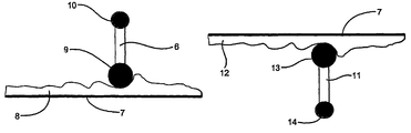
- FIGS. 3( a ) and 3 ( b ) show sealing elements for use in accordance with the invention
- FIG. 4 shows schematically a sealing element of the kind shown in FIGS. 3( a ) and 3 ( b ) in place to seal or stem a leak.
- FIG. 5 shows schematically a leak location apparatus for use in accordance with the present invention
- FIG. 6 shows a relationship between the apparatus of FIG. 5 when provided in a pipe with a leak and a measurement of flow field
- FIG. 7 illustrates an array of differential sensors for use in the apparatus shown in FIG. 5 ;
- FIG. 8 illustrates one example of detected pressure characteristics of a leak using the sensor array of FIG. 7 ;
- FIG. 9 illustrates schematically, and cross-sectionally of a pipe, a composite sealing element for use in certain embodiments of the invention.
- the present invention can be applied to fluids generally, for example, oil, water, natural gas etc.
- the present embodiment will be described with respect to water.
- a fluid passes through pipework, it can be represented as a flow field varying according to the spatial location within the pipe.
- the characteristics of the fluid flow field will vary according to a large number of parameters, including for example pipe size (diameter), fluid pressure, pipe surface characteristics, the type of flow, side passages, directional variation of the pipe etc.
- Another parameter that will modify the fluid flow field characteristics is the presence of a leak. Indeed, the degree of modification of the fluid flow field characteristics will vary according to the form of leak, for example its size, type, geometry and location within the pipe.
- the inventor considers that a part of the reason for the very small localised effect of a leak is that the flow within the pipe recovers very quickly after the leak.
- the disturbance in the flow field characteristic probably derives from a velocity component of the leaking water as it flows through the leak, this velocity component being essentially normal to the direction of the gross flow of water in the pipe.
- the effect of this component will be small within the terms of the gross water flow and will disappear rapidly either side of the leak.
- a leak location system comprises a sensor means, in the form of a capsule 2 , which is located in a pipe section 1 through which water is flowing in the direction of the arrow.
- the pipe section has preset parameters.
- the capsule has dispersed around its periphery a plurality of sensors 3 for measuring a fluid flow field characteristic within the pipe interior. Measurements taken by the sensors 3 are communicated to a remote computer 4 .
- the measurements may be communicated in real time, for example by way of a transmitter on the capsule and a suitable receiver for the computer.
- the measurements may be stored in a memory on the capsule, for example on a smart card, the data from which can be transferred to the computer following a passage of the capsule within the section of pipe.
- the capsule 2 is arranged to traverse along the interior of the pipe in the flow of water.
- the capsule may rely on the flow of water to carry it through a designated section of pipe, or it may be provided with propulsion means for affording it independent movement within the flow.
- the capsule is provided with location means whereby the location of the capsule within the pipe section can be determined.
- the location means may comprise, for example, ultrasonic sensors for accurately measuring distances to pipe walls and/or GSM technology for accurately determining the position of the sensor within e.g. a long stretch of pipe.
- a movement control means can also be provided for adjusting the spatial position of the capsule.
- Such movement control means may include radio controlled vanes or fins or the like for guiding the capsule within the flow.
- the data from the measurements of the sensors are processed by a processing means and stored in memory.
- a series of data are obtained from pipe sections having different parameters and with and without leaks of varying forms whereby a library of fluid flow field characteristics is built up which can be differentiated according to these parameters.
- the artificial neural network learns to classify the fluid flow field characteristics with more and more accuracy.
- a suitable inlet in the pipe is required for insertion of the capsule into the flow.
- the capsule 2 traverses along the pipe taking separate pressure measurements from the individual pressure sensors 3 . Such measurements are recorded within the capsule.
- the fluid flow field characteristics as represented by the pressure measurements are modified by the presence of a leak 5 as shown by the pressure contour 6 .
- the pressure measurements taken by the sensors on the capsule provide information about the presence of the leak according to the graphical plot of pressure in relation to distance along the pipe section, as shown in the figure.
- the plot is only illustrative and will vary depending on the geometry of the leak.
- the measurements taken by the capsule are not necessarily particularly helpful on their own in establishing conditions within the pipe, e.g. the position and geometry of the leak.
- they are compared with similar measurements from other pipe sections having known internal conditions.
- Such known measurements may be held by the computer in a library of prior measurement and associated pipe internal condition data.
- the measurements can be used to form a fluid flow field signature of the pipe under examination as shown generally by the plot in FIG. 6 .
- a signature can be readily compared with signatures formed for prior known pipe internal configurations to draw out relevant characteristics.
- neural networks may be employed. Pre-processing of the measurements can be conducted using several techniques such as principal component analysis, wavelet transforms, and higher order spectral analysis. With use of pre-processing of the signal, it is possible to extract the maximum amount of detail about pertinent aspects of the signatures whilst minimising unwanted information and noise.
- FIG. 7 illustrates an array of sensors which provides a more sensitive form of sensor means that can be applied to the capsule 2 shown in FIG. 1 .
- four differential pressure sensors e.g. Honeywell 24 PCA
- the sensors can resolve small localised pressure differentials enabling the detection of the small pressure drops resulting from leaks.
- the angular arrangement of the outlets spatial location of the leak is provided.
- pressure differential it will be appreciated that the pressure will depend on the depth of the outlet in the water. For example, each 10 mm of depth represents 100 Pa.
- the sensors can easily detect a differential pressure between the outlets in the presence of a leak.
- FIG. 8 illustrates an example of detected fluid flow characteristics in the form of pressure.
- this figure shows results from a pipe of 0.2 m diameter with a water flow rate therethrough of 20 l/s at a pressure of 1 bar (10 5 Pa).
- a hole of diameter 0.01 m has been made in the pipe at a specific location providing a leakage of 0.7 l/s.
- the capsule 2 is moved incrementally along the pipe to take readings.
- the increments are 0.1 m.
- the capsule is moved incrementally in this case so that localised turbulence caused by the capsule subsides to provide more stable readings.
- the size of the increment can be reduced and by application of suitable pre-processing techniques as mentioned above, the instability of the readings resulting from localised turbulence can be filtered out to provide a cleaner overall characteristic or signature.
- the difference in differential pressure between the lines for sensors A-B and A-D in FIG. 5 could either be an intrinsic instrument offset or a relative tilt of the sensors.
- the magnitude of the leak is related to the pressure drop measured by the differential pressure sensors. Moreover, it will be noted that since the outlets D-A are remote from the position of the leak, no differential pressure drop is detected. This further illustrates the localised nature of the disturbance in the fluid field characteristic. Whilst the detected magnitude of the pressure drop is related to the magnitude of the leak, it is apparent that the further from the leak, the smaller the magnitude of the pressure drop. Nevertheless, by using the differential pressure from openings B-C (not shown in FIG. 4 for convenience), it is possible to still resolve out a pressure drop that is representative of the magnitude of the leak.
- FIG. 8 Whilst the results of FIG. 8 show a simple pressure drop for tapping points A-B that is compared with the reference pressure drop for tapping points D-A, it will be appreciated that by using the analytical techniques mentioned above, greater accuracy in leak detection and information about the leak in relation to specific pipework can be obtained.
- FIG. 1 there is shown a related arrangement of a sealing element 1 in the form of a flexible membrane comprising a sheet of plastics or other suitable material having one pair of opposing sides joined together, and being cut so as to present open ends 2 and 3 and to adopt a frustoconical form when filled with the fluid in a pipe (not shown in FIG. 1 ).
- the location of a leak is known as a result, for example, of the use of the sensor described with reference to FIGS. 5 to 8 and as described in the aforesaid International Patent Application and the sealing element 1 is thus intended to be transported to the area of the leak, for example by being towed through the subject pipework behind the sensor actually used to locate the leak, or behind another device that is guided to the relevant area, either by the sensor itself or by remote transmitter means.
- the pressure differential associated with the leak which, in a mains water pipe can be as much as 16 bar, is effective to draw the element 1 into the leakage aperture itself, as shown in FIG. 2 , and the doubled sheet is thus pulled against the inner wall 4 of the pipe, shown in part at 5 .
- the sheet of the sealing element 1 carries a suitable bonding agent which enables the element to be firmly adherent to the inner wall 4 .
- the bonding agent may be contained in microcapsules which burst in response to the pressure imparted to the element 1 when it is in position to seal the leak.
- Pressure sensitive release means may be incorporated in the towing link which enable the towing vehicle to leave the sealing element behind at the site of the leak and proceed alone to a suitable collection point.
- the towing vehicle (assuming that the leak sensor itself is not used for that purpose) may be regarded as disposable and remain attached to the sealing element with any motive power disabled by remote control.
- one or more simple streamers can be used if preferred. If streamers are used, there may usefully be several, these having varying degrees of positive and negative buoyancy, as well as some of neutral buoyancy which can drift from side to side. By this means, there is provided an increased probability that one or more streamers will be positioned within the pipe so as to be “captured” by the pressure differential associated with the leak, and thus able to move into the leaking area and effect the desired sealing or stemming.
- the leak sensor device will be re-employed to investigate the extent to which the action has been successful. If the action has not been successful, and/or has succeeded only to a degree, a follow-up operation may be carried out, using any of the procedures described above. In the event that a follow-up operation is required to improve or complete the sealing, then sealing elements of different dimensions and/or of different materials to those used in the first operation may be employed.
- sealing elements used in a follow-up operation may carry a different bonding medium to that carried by the element(s) used in the original operation, bearing in mind that they will need to bond primarily to the material of the element(s) already in place, rather than to the wall 4 of the tube 5 .
- the element(s) used in a follow-up operation may not be required to carry any bonding material at all, especially if the material of the elements exhibits a degree of surface roughness that provides frictional inter-engagement.
- sealing elements of the kind described above can be introduced into pipework without any knowledge of the location of a leak and/or without the use of towing or steerage devices, thereby to be carried along the pipe by the flow of fluid therein and attracted to the site of a leak by the aforementioned pressure differential. If this approach is to be adopted, however, it is preferred that sealing elements of the kind shown at 6 and 11 in FIG. 3 are employed.
- freely mobile elements such as 6
- flexible membrane are released into a pipe 7 , part of the bottom wall of which is shown at 8 .
- the surface of wall 8 is shown as being roughened by the presence of sediment, scaling and/or other deposits.
- each element such as 6 resemble tadpoles, and typically take the form of small streamers or flow socks.
- each element such as 6 is provided with one or more floats such as 9 and 10 .
- the various elements such as 6 are provided with respective pairs of floats having different buoyancy characteristics, so that different elements will be borne at differing heights within the pipe, thereby to increase the probability that wherever, around the circumference of a pipe, a leak may exist, one or more elements is or are disposed and presented so as to be captured by the localised pressure differential attributable to the leak and pulled into sealing relationship with the leakage aperture.
- the element 6 is provided with a relatively large float 9 of negative buoyancy and a relatively small float 10 of positive buoyancy.
- the net buoyancy is negative, so the element 6 tends to bump along the bottom wall 8 , driven by the fluid flow.
- the small, positively buoyant float 10 allows the flow-based inertial forces within the pipe to move the element 6 if it has become trapped in the roughness on the pipe wall. Once near a leak, the differential pressure forces will dominate over the inertial forces and so the element (provided it is suitably dimensioned) will be drawn into position to seal the leak, and will be held there.
- a suitable bonding agent may be borne by the element 6 to ensure its firm adhesion at the desired location.
- elements such as 6 of differing sizes may be introduced into the pipe 7 ; and in some circumstances it is preferred to introduce the elements in size groups, starting with the largest. This strategy reduces the risk of small elements being drawn out through a leakage aperture and thus lost to the system.
- FIG. 3( b ) shows another tadpole-like element 11 which is inversely constructed as regards buoyancy to the element 6 , and is thus caused to bump along the top wall 12 of the pipe 7 .
- the element 11 has a relatively large positively buoyant float 13 and a relatively small negatively buoyant float 14 , but operates in a similar way to the float 6 .
- the linking connection may be so constructed as to dissolve or change in length during exposure, over a prescribed period of time, to the fluid content of the pipe.
- FIG. 9 shows that the equilibrium position for the sealing elements 90 , 91 would be at the mid-height of the pipe 1 as the elements are of equal buoyancy and, because of the length of the linking connection 92 , they cannot position themselves in any other arrangement. Likewise, positively buoyant sealing elements linked with a connection shorter than connection 92 will naturally float closer to the top of the pipe 1 .
- connection such as 92
- the link 92 were constructed so as to shorten significantly, the link can be configured to fold over, allowing the two elements 90 and 91 to bond together and jointly contribute to the seal.
- sealing elements of a number of configurations, such as frustoconical, rectangular, tubular etc., with varying material stiffness and some with interconnecting links as just described.
- the efficiency of the sealing process may be enhanced by reducing the flow rate of fluid in the pipe zone being treated, whilst maintaining the operative pressure. This increases the probability of elements being entrained into the leakage aperture by the pressure differential associated with the leak, since that pressure, in such circumstances, becomes very much the dominant force acting upon the relevant elements.
- a pipework loop containing water pressurised to 1.4 bar was provided with a leak of diameter 10 mm, giving a leakage rate of 0.7 l/s.
- a windsock-shaped sealing element such as that shown in FIG. 1 of front diameter 80 mm; rear diameter 20 mm and length 300 mm was attached to a sensor device, or “fish” as it is typically called, using four lengths of cable, each 400 mm in length. When the fish was dragged past the leak, the windsock-shaped element was sucked to the leak and sealed it completely, reducing the leakage to zero.
- sealing elements are preferably constructed so as to be capable of use with a signalling system for leak and/or positional detection purposes.
- Such elements may either transmit under their own power to a remote location outside of the pipe; transmit to a pipework-borne transponder which in turn transmits (either automatically or in response to an interrogating stimulus) to the remote location; or transmit within the pipe for detection by an intelligent unit traversing the pipe.
- a tagged element may merely contain an electrically conductive loop which is sensed by an intelligent unit traversing the pipe and/or by external sensors, in a technical sense rather in the manner of security tags used in departmental stores and the like.
- the tagging technology used may be active (requiring an on-board power source) or passive (not requiring an on-board power source).
- any convenient signalling technology may be adopted, depending upon various criteria such as the fluid flowing in the pipe, the materials, dimensions and condition of the pipework, the environment surrounding the pipework and so on.
- Candidate technologies include the transmission and/or reception of electrical, electronic, magnetic, electromagnetic, optical, vibrational, acoustic, or ultrasonic signals and chemical or radioactive markers.
- an intelligent unit (sometimes called a pipeline PIG) is caused to traverse the pipe and is provided with sensors to detect the presence of the passive tag. Once detected, this information is correlated with the PIG's distance travelled and/or other information that provides an accurate position for the leak.
- the positional information may be transmitted by the PIG in real time to an external location where it can be detected and the information used straight away, or stored on the PIG for later analysis.
- the tag may be used by itself to transmit signals via any convenient medium, such as along or through the pipe wall, though the fluid in the pipe, and/or through the environment surrounding the pipework. If pulsed signals are transmitted, timing processes can be used to evaluate distance. Any information transmitted externally of the pipework may be routed to a remote receiver via transponders supported on, or close to, the pipework, or they may be picked up directly by detector/receivers placed close to the pipework. In the case of buried pipework, detector/receivers may be lowered into test bores made close to a suspected leak site.
Landscapes
- Engineering & Computer Science (AREA)
- General Engineering & Computer Science (AREA)
- Mechanical Engineering (AREA)
- Chemical & Material Sciences (AREA)
- Combustion & Propulsion (AREA)
- Examining Or Testing Airtightness (AREA)
- Medicines That Contain Protein Lipid Enzymes And Other Medicines (AREA)
- Medicines Containing Material From Animals Or Micro-Organisms (AREA)
- Pipe Accessories (AREA)
- Pipeline Systems (AREA)
- Paper (AREA)
- Patch Boards (AREA)
- Valve Device For Special Equipments (AREA)
- Rigid Pipes And Flexible Pipes (AREA)
Priority Applications (1)
| Application Number | Priority Date | Filing Date | Title |
|---|---|---|---|
| US13/253,301 US20120080114A1 (en) | 2000-05-09 | 2011-10-05 | Duct leakage control |
Applications Claiming Priority (2)
| Application Number | Priority Date | Filing Date | Title |
|---|---|---|---|
| GBGB0011190.6A GB0011190D0 (en) | 2000-05-09 | 2000-05-09 | Duct leakage control |
| GB0011190.6 | 2000-05-09 |
Related Child Applications (1)
| Application Number | Title | Priority Date | Filing Date |
|---|---|---|---|
| US13/253,301 Continuation US20120080114A1 (en) | 2000-05-09 | 2011-10-05 | Duct leakage control |
Publications (2)
| Publication Number | Publication Date |
|---|---|
| US20030160391A1 US20030160391A1 (en) | 2003-08-28 |
| US8061389B2 true US8061389B2 (en) | 2011-11-22 |
Family
ID=9891266
Family Applications (2)
| Application Number | Title | Priority Date | Filing Date |
|---|---|---|---|
| US10/275,742 Expired - Lifetime US8061389B2 (en) | 2000-05-09 | 2001-05-08 | Duct leakage control |
| US13/253,301 Abandoned US20120080114A1 (en) | 2000-05-09 | 2011-10-05 | Duct leakage control |
Family Applications After (1)
| Application Number | Title | Priority Date | Filing Date |
|---|---|---|---|
| US13/253,301 Abandoned US20120080114A1 (en) | 2000-05-09 | 2011-10-05 | Duct leakage control |
Country Status (14)
| Country | Link |
|---|---|
| US (2) | US8061389B2 (de) |
| EP (1) | EP1282799B1 (de) |
| AT (1) | ATE430894T1 (de) |
| AU (1) | AU2001254944A1 (de) |
| BR (1) | BR0110995B1 (de) |
| CA (1) | CA2409886C (de) |
| DE (1) | DE60138616D1 (de) |
| DK (1) | DK1282799T3 (de) |
| EA (1) | EA004112B1 (de) |
| ES (1) | ES2328012T3 (de) |
| GB (1) | GB0011190D0 (de) |
| NO (1) | NO330289B1 (de) |
| PT (1) | PT1282799E (de) |
| WO (1) | WO2001086191A1 (de) |
Cited By (9)
| Publication number | Priority date | Publication date | Assignee | Title |
|---|---|---|---|---|
| US20110042902A1 (en) * | 2008-01-23 | 2011-02-24 | Heriot-Watt University | Self-sealing method |
| US20110221137A1 (en) * | 2008-11-20 | 2011-09-15 | Udoka Obi | Sealing method and apparatus |
| US20120067447A1 (en) * | 2009-04-16 | 2012-03-22 | Nicholas John Ryan | Delivery method and compositions |
| US9188467B1 (en) | 2013-11-21 | 2015-11-17 | Marisela Payne | Visual sight flexible gas flow indicator |
| US9261218B2 (en) | 2013-07-31 | 2016-02-16 | Elwha Llc | Pipeline leak sealing system and method |
| US9709204B2 (en) | 2013-07-31 | 2017-07-18 | Elwha Llc | Systems and methods for pipeline device propulsion |
| US20170276284A1 (en) * | 2016-03-28 | 2017-09-28 | Hyperloop Technologies, Inc. | Systems and methods for leak detection and sealing |
| US10184678B2 (en) | 2013-09-06 | 2019-01-22 | Carrier Corporation | System and method for measuring duct leakage in a HVAC system |
| US11320082B2 (en) * | 2017-05-11 | 2022-05-03 | Qinov8 Uk Ltd | Sealing element |
Families Citing this family (19)
| Publication number | Priority date | Publication date | Assignee | Title |
|---|---|---|---|---|
| CA2329504C (en) * | 2000-12-22 | 2004-01-20 | Canadian Mining Industry Research Organization/Organisation De Recherche De L'industrie Miniere Canadienne | Device for in-line measurement of properties of fluid flows in pipeline systems |
| GB0209771D0 (en) * | 2002-04-29 | 2002-06-05 | Univ Aberdeen | Duct leakage control |
| GB2423562B (en) * | 2005-05-27 | 2007-01-17 | Brinker Technology Ltd | Determining leak location and size in pipes |
| GB0723661D0 (en) | 2007-12-03 | 2008-01-16 | Brinker Technology Ltd | Leak sealing |
| GB0801461D0 (en) * | 2008-01-25 | 2008-03-05 | Brinker Technology Ltd | Duct assessment and leak sealing method for ducts transporting gas |
| BRPI0800473B1 (pt) * | 2008-03-05 | 2020-04-22 | Petroleo Brasileiro S.A. - Petrobras | sistema e processo para detecção de vazamento em umbilicais |
| GB0804566D0 (en) * | 2008-03-12 | 2008-04-16 | Brinker Technology Ltd | Method for sealing a leak in a vessel or duct |
| US8282013B2 (en) | 2009-01-16 | 2012-10-09 | Parker-Hannifin Corporation | RFID-tagged seal |
| US9328857B2 (en) * | 2009-08-04 | 2016-05-03 | Zia Systems, Llc | System and method for real-time tracking of objects |
| US9651445B2 (en) * | 2013-04-15 | 2017-05-16 | Ut-Battelle, Llc | Fluid pipeline leak detection and location with miniature RF tags |
| US10513653B2 (en) | 2015-04-28 | 2019-12-24 | Thru Tubing Solutions, Inc. | Flow control in subterranean wells |
| US11851611B2 (en) | 2015-04-28 | 2023-12-26 | Thru Tubing Solutions, Inc. | Flow control in subterranean wells |
| US9745820B2 (en) | 2015-04-28 | 2017-08-29 | Thru Tubing Solutions, Inc. | Plugging device deployment in subterranean wells |
| US10774612B2 (en) | 2015-04-28 | 2020-09-15 | Thru Tubing Solutions, Inc. | Flow control in subterranean wells |
| WO2018200698A1 (en) | 2017-04-25 | 2018-11-01 | Thru Tubing Solutions, Inc. | Plugging undesired openings in fluid conduits |
| CA3058511C (en) * | 2017-04-25 | 2022-08-23 | Thru Tubing Solutions, Inc. | Plugging undesired openings in fluid vessels |
| CN113464852B (zh) * | 2021-07-26 | 2022-11-08 | 广东电网有限责任公司 | 一种管道漏水点自动定位设备 |
| US12584372B2 (en) * | 2023-08-30 | 2026-03-24 | Thru Tubing Solutions, Inc. | Anchoring plugging devices to perforations |
| US20250146611A1 (en) * | 2023-11-06 | 2025-05-08 | Saudi Arabian Oil Company | Smart Scale Locator |
Citations (18)
| Publication number | Priority date | Publication date | Assignee | Title |
|---|---|---|---|---|
| US3144049A (en) * | 1962-06-28 | 1964-08-11 | Standard Oil Co | Method for sealing leaks and leak sealant |
| US3298399A (en) | 1964-10-27 | 1967-01-17 | Warren Petroleum Corp | Apparatus to detect and temporarily seal a leak in a pipeline |
| GB1101870A (en) | 1966-09-09 | 1968-01-31 | Georg Woerle | Improvements in or relating to sealing bodies for sealing apertures in piping carrying fluid under pressure and to applications thereof |
| US3837214A (en) * | 1973-01-30 | 1974-09-24 | Halliburton Co | Self-propelled pipeline plug |
| US3974680A (en) * | 1975-05-27 | 1976-08-17 | Inspection Technology Development, Inc. | Pipeline leak detector |
| US4016748A (en) | 1975-11-10 | 1977-04-12 | Boyens Virgil C | Pipeline and leak locater and method |
| US4402213A (en) * | 1980-10-14 | 1983-09-06 | Agl Corporation | Method and device for detecting and locating leaks in pipelines |
| US4582091A (en) | 1982-02-02 | 1986-04-15 | The British Petroleum Company P.L.C. | Leak sealing method |
| US4714095A (en) * | 1985-06-10 | 1987-12-22 | Hans Muller | Method of salvaging a pipe conduit buried under ground |
| EP0303048A1 (de) | 1987-08-13 | 1989-02-15 | STAHLGRUBER Otto Gruber GmbH & Co. | Reparaturflicken für Gummi-und Kunststoffgegenstände |
| US4894539A (en) * | 1986-08-22 | 1990-01-16 | Imperial Chemical Industries Plc | Leak detector |
| US5680885A (en) * | 1992-10-08 | 1997-10-28 | Catallo; Giulio | Method for rehabilitating pipe |
| GB2334532A (en) | 1998-02-19 | 1999-08-25 | Truetzschler Gmbh & Co Kg | Preparing fibres for spinning : separating foreign matter |
| US6161588A (en) * | 1995-11-01 | 2000-12-19 | Bellamy; Norman West | Lining of pipelines and passageways |
| US6206049B1 (en) * | 1998-11-20 | 2001-03-27 | Tele Environmental Systems | Apparatus and method for the robotic repairing of an underground pipe junction with removable heating element |
| US6615875B2 (en) * | 2000-08-30 | 2003-09-09 | Owens Corning Composites Sprl. | Liner for reinforcing a pipe and method of making the same |
| GB2400898A (en) | 2003-04-25 | 2004-10-27 | Anthony O'donnell | Method and apparatus for repairing a pipe |
| US6931952B2 (en) * | 2000-12-22 | 2005-08-23 | Canadian Mining Industry Research Organization | Device for in-line measurement of properties of fluid flows in pipeline systems |
Family Cites Families (9)
| Publication number | Priority date | Publication date | Assignee | Title |
|---|---|---|---|---|
| US2754910A (en) * | 1955-04-27 | 1956-07-17 | Chemical Process Company | Method of temporarily closing perforations in the casing |
| US4187909A (en) * | 1977-11-16 | 1980-02-12 | Exxon Production Research Company | Method and apparatus for placing buoyant ball sealers |
| US4329132A (en) * | 1980-10-06 | 1982-05-11 | Rockwell International Corporation | Hole plugging system |
| US4715747A (en) * | 1986-06-20 | 1987-12-29 | Behrens Robert N | Air motivated conduit prover apparatus |
| US5485882A (en) * | 1994-10-27 | 1996-01-23 | Exxon Production Research Company | Low-density ball sealer for use as a diverting agent in hostile environment wells |
| GB0209771D0 (en) * | 2002-04-29 | 2002-06-05 | Univ Aberdeen | Duct leakage control |
| GB2423562B (en) * | 2005-05-27 | 2007-01-17 | Brinker Technology Ltd | Determining leak location and size in pipes |
| US7647964B2 (en) * | 2005-12-19 | 2010-01-19 | Fairmount Minerals, Ltd. | Degradable ball sealers and methods for use in well treatment |
| US8205677B1 (en) * | 2010-06-28 | 2012-06-26 | Samuel Salkin | System and method for controlling underwater oil-well leak |
-
2000
- 2000-05-09 GB GBGB0011190.6A patent/GB0011190D0/en not_active Ceased
-
2001
- 2001-05-08 AT AT01928078T patent/ATE430894T1/de active
- 2001-05-08 CA CA2409886A patent/CA2409886C/en not_active Expired - Fee Related
- 2001-05-08 EP EP01928078A patent/EP1282799B1/de not_active Expired - Lifetime
- 2001-05-08 EA EA200201189A patent/EA004112B1/ru not_active IP Right Cessation
- 2001-05-08 BR BRPI0110995-2A patent/BR0110995B1/pt not_active IP Right Cessation
- 2001-05-08 DK DK01928078T patent/DK1282799T3/da active
- 2001-05-08 DE DE60138616T patent/DE60138616D1/de not_active Expired - Lifetime
- 2001-05-08 US US10/275,742 patent/US8061389B2/en not_active Expired - Lifetime
- 2001-05-08 AU AU2001254944A patent/AU2001254944A1/en not_active Abandoned
- 2001-05-08 WO PCT/GB2001/002002 patent/WO2001086191A1/en not_active Ceased
- 2001-05-08 ES ES01928078T patent/ES2328012T3/es not_active Expired - Lifetime
- 2001-05-08 PT PT01928078T patent/PT1282799E/pt unknown
-
2002
- 2002-11-08 NO NO20025367A patent/NO330289B1/no not_active IP Right Cessation
-
2011
- 2011-10-05 US US13/253,301 patent/US20120080114A1/en not_active Abandoned
Patent Citations (19)
| Publication number | Priority date | Publication date | Assignee | Title |
|---|---|---|---|---|
| US3144049A (en) * | 1962-06-28 | 1964-08-11 | Standard Oil Co | Method for sealing leaks and leak sealant |
| US3298399A (en) | 1964-10-27 | 1967-01-17 | Warren Petroleum Corp | Apparatus to detect and temporarily seal a leak in a pipeline |
| GB1101870A (en) | 1966-09-09 | 1968-01-31 | Georg Woerle | Improvements in or relating to sealing bodies for sealing apertures in piping carrying fluid under pressure and to applications thereof |
| US3837214A (en) * | 1973-01-30 | 1974-09-24 | Halliburton Co | Self-propelled pipeline plug |
| US3974680A (en) * | 1975-05-27 | 1976-08-17 | Inspection Technology Development, Inc. | Pipeline leak detector |
| US4016748A (en) | 1975-11-10 | 1977-04-12 | Boyens Virgil C | Pipeline and leak locater and method |
| US4402213A (en) * | 1980-10-14 | 1983-09-06 | Agl Corporation | Method and device for detecting and locating leaks in pipelines |
| US4582091A (en) | 1982-02-02 | 1986-04-15 | The British Petroleum Company P.L.C. | Leak sealing method |
| US4714095A (en) * | 1985-06-10 | 1987-12-22 | Hans Muller | Method of salvaging a pipe conduit buried under ground |
| US4894539A (en) * | 1986-08-22 | 1990-01-16 | Imperial Chemical Industries Plc | Leak detector |
| EP0303048A1 (de) | 1987-08-13 | 1989-02-15 | STAHLGRUBER Otto Gruber GmbH & Co. | Reparaturflicken für Gummi-und Kunststoffgegenstände |
| US4913950A (en) | 1987-08-13 | 1990-04-03 | Stahlgruber Otto Gruber Gmbh & Co. | Repair patch for rubber and plastic articles |
| US5680885A (en) * | 1992-10-08 | 1997-10-28 | Catallo; Giulio | Method for rehabilitating pipe |
| US6161588A (en) * | 1995-11-01 | 2000-12-19 | Bellamy; Norman West | Lining of pipelines and passageways |
| GB2334532A (en) | 1998-02-19 | 1999-08-25 | Truetzschler Gmbh & Co Kg | Preparing fibres for spinning : separating foreign matter |
| US6206049B1 (en) * | 1998-11-20 | 2001-03-27 | Tele Environmental Systems | Apparatus and method for the robotic repairing of an underground pipe junction with removable heating element |
| US6615875B2 (en) * | 2000-08-30 | 2003-09-09 | Owens Corning Composites Sprl. | Liner for reinforcing a pipe and method of making the same |
| US6931952B2 (en) * | 2000-12-22 | 2005-08-23 | Canadian Mining Industry Research Organization | Device for in-line measurement of properties of fluid flows in pipeline systems |
| GB2400898A (en) | 2003-04-25 | 2004-10-27 | Anthony O'donnell | Method and apparatus for repairing a pipe |
Non-Patent Citations (1)
| Title |
|---|
| Merriam-Webster's Collegiate Dictionary, Tenth Edition, pp. 660, 724 and 1079. * |
Cited By (13)
| Publication number | Priority date | Publication date | Assignee | Title |
|---|---|---|---|---|
| US20110042902A1 (en) * | 2008-01-23 | 2011-02-24 | Heriot-Watt University | Self-sealing method |
| US8459354B2 (en) * | 2008-01-23 | 2013-06-11 | Heriot-Watt University | Self-sealing method |
| US20110221137A1 (en) * | 2008-11-20 | 2011-09-15 | Udoka Obi | Sealing method and apparatus |
| US20120067447A1 (en) * | 2009-04-16 | 2012-03-22 | Nicholas John Ryan | Delivery method and compositions |
| US8950438B2 (en) * | 2009-04-16 | 2015-02-10 | Brinker Technology Ltd | Method and compositions for delivery of a concentrated quantity of sealing elements to a leak site in a vessel |
| US9261218B2 (en) | 2013-07-31 | 2016-02-16 | Elwha Llc | Pipeline leak sealing system and method |
| US9587780B2 (en) | 2013-07-31 | 2017-03-07 | Elwha Llc | Pipeline leak sealing system and method |
| US9709204B2 (en) | 2013-07-31 | 2017-07-18 | Elwha Llc | Systems and methods for pipeline device propulsion |
| US10184678B2 (en) | 2013-09-06 | 2019-01-22 | Carrier Corporation | System and method for measuring duct leakage in a HVAC system |
| US9188467B1 (en) | 2013-11-21 | 2015-11-17 | Marisela Payne | Visual sight flexible gas flow indicator |
| US20170276284A1 (en) * | 2016-03-28 | 2017-09-28 | Hyperloop Technologies, Inc. | Systems and methods for leak detection and sealing |
| US10309574B2 (en) * | 2016-03-28 | 2019-06-04 | Hyperloop Technologies, Inc. | Systems and methods for leak detection and sealing |
| US11320082B2 (en) * | 2017-05-11 | 2022-05-03 | Qinov8 Uk Ltd | Sealing element |
Also Published As
| Publication number | Publication date |
|---|---|
| WO2001086191A1 (en) | 2001-11-15 |
| DK1282799T3 (da) | 2009-09-07 |
| NO330289B1 (no) | 2011-03-21 |
| CA2409886A1 (en) | 2001-11-15 |
| US20030160391A1 (en) | 2003-08-28 |
| BR0110995B1 (pt) | 2011-01-11 |
| ES2328012T3 (es) | 2009-11-06 |
| NO20025367L (no) | 2003-01-08 |
| ATE430894T1 (de) | 2009-05-15 |
| NO20025367D0 (no) | 2002-11-08 |
| EP1282799B1 (de) | 2009-05-06 |
| BR0110995A (pt) | 2003-03-11 |
| CA2409886C (en) | 2011-07-26 |
| AU2001254944A1 (en) | 2001-11-20 |
| DE60138616D1 (de) | 2009-06-18 |
| EA200201189A1 (ru) | 2003-04-24 |
| US20120080114A1 (en) | 2012-04-05 |
| EP1282799A1 (de) | 2003-02-12 |
| EA004112B1 (ru) | 2003-12-25 |
| PT1282799E (pt) | 2009-09-01 |
| GB0011190D0 (en) | 2000-06-28 |
Similar Documents
| Publication | Publication Date | Title |
|---|---|---|
| US8061389B2 (en) | Duct leakage control | |
| US6935425B2 (en) | Method for utilizing microflowable devices for pipeline inspections | |
| El-Zahab et al. | Leak detection in water distribution networks: an introductory overview | |
| Al Qahtani et al. | A review on water leakage detection method in the water distribution network | |
| CA2485180C (en) | Duct seepage reduction | |
| EP2205825B1 (de) | Intelligentes unterwasserleckagedetektionssystem | |
| US20140130577A1 (en) | Leak Detection Apparatus | |
| US9651445B2 (en) | Fluid pipeline leak detection and location with miniature RF tags | |
| CN105467000A (zh) | 埋地管道管体缺陷非开挖检测方法及装置 | |
| Abdulazeez et al. | IOT-enabled intelligent drones for leak detection with using simple text oriented messaging protocol (STOMP) | |
| Kurtz | Developments in a free-swimming acoustic leak detection system for water transmission pipelines | |
| CN105987285A (zh) | 一种管道异常点的快速检测方法 | |
| IL127202A (en) | Method and device for controlling the flow of liquids in at least one pipe, in particular clarification of areas of lack of flow | |
| Shukla et al. | Unsupervised classification of flow-induced vibration signals to detect leakages in water distribution pipelines | |
| US4375763A (en) | Device for detecting and locating leaks in pipelines | |
| van Pol et al. | The future of in-line inspection: free-floating smart sensors | |
| Ariaratnam et al. | Development of an innovative free-swimming device for detection of leaks in oil and gas pipelines | |
| WO2000028296A1 (en) | Leak location method and system | |
| Awolusi et al. | Emerging technologies and systems for gas pipeline leak detection | |
| Exaudi et al. | Leak Detection in Water Pipe using FSR (Force Sensitive Resistor) Sensor | |
| Mohd Yussof et al. | Review of Water Leak Detection Methods in Smart Building Applications. Buildings 2022, 12, 1535 | |
| AU2019477996A1 (en) | Method and system to determine variations in a fluidic channel | |
| Galleher et al. | Evaluation of an un-tethered free-swimming acoustic leak detection technology | |
| Yang | Water leak detection and localization using multi-sensor data fusion | |
| Chatzigeorgiou et al. | In-pipe acoustic characterization of leak signals in plastic water-filled pipes |
Legal Events
| Date | Code | Title | Description |
|---|---|---|---|
| AS | Assignment |
Owner name: ABERDEEN UNIVERSITY, GREAT BRITAIN Free format text: ASSIGNMENT OF ASSIGNORS INTEREST;ASSIGNOR:MCEWAN, IAN KENNETH;REEL/FRAME:013937/0096 Effective date: 20030303 |
|
| AS | Assignment |
Owner name: BRINKER TECHNOLOGY LIMITED, UNITED KINGDOM Free format text: ASSIGNMENT OF ASSIGNORS INTEREST;ASSIGNOR:ABERDEEN UNIVERSITY;REEL/FRAME:020877/0200 Effective date: 20080324 |
|
| STCF | Information on status: patent grant |
Free format text: PATENTED CASE |
|
| AS | Assignment |
Owner name: SEAL-TITE, LLC, LOUISIANA Free format text: ASSIGNMENT OF ASSIGNORS INTEREST;ASSIGNOR:BRINKER TECHNOLOGY LIMITED;REEL/FRAME:032746/0918 Effective date: 20121019 |
|
| FPAY | Fee payment |
Year of fee payment: 4 |
|
| MAFP | Maintenance fee payment |
Free format text: PAYMENT OF MAINTENANCE FEE, 8TH YR, SMALL ENTITY (ORIGINAL EVENT CODE: M2552); ENTITY STATUS OF PATENT OWNER: SMALL ENTITY Year of fee payment: 8 |
|
| MAFP | Maintenance fee payment |
Free format text: PAYMENT OF MAINTENANCE FEE, 12TH YR, SMALL ENTITY (ORIGINAL EVENT CODE: M2553); ENTITY STATUS OF PATENT OWNER: SMALL ENTITY Year of fee payment: 12 |