US8061289B2 - Marine lifting apparatus - Google Patents
Marine lifting apparatus Download PDFInfo
- Publication number
- US8061289B2 US8061289B2 US12/435,134 US43513409A US8061289B2 US 8061289 B2 US8061289 B2 US 8061289B2 US 43513409 A US43513409 A US 43513409A US 8061289 B2 US8061289 B2 US 8061289B2
- Authority
- US
- United States
- Prior art keywords
- frame
- vessel
- lifting apparatus
- catamaran
- vessels
- Prior art date
- Legal status (The legal status is an assumption and is not a legal conclusion. Google has not performed a legal analysis and makes no representation as to the accuracy of the status listed.)
- Active
Links
Images


Classifications
-
- B—PERFORMING OPERATIONS; TRANSPORTING
- B63—SHIPS OR OTHER WATERBORNE VESSELS; RELATED EQUIPMENT
- B63C—LAUNCHING, HAULING-OUT, OR DRY-DOCKING OF VESSELS; LIFE-SAVING IN WATER; EQUIPMENT FOR DWELLING OR WORKING UNDER WATER; MEANS FOR SALVAGING OR SEARCHING FOR UNDERWATER OBJECTS
- B63C7/00—Salvaging of disabled, stranded, or sunken vessels; Salvaging of vessel parts or furnishings, e.g. of safes; Salvaging of other underwater objects
- B63C7/02—Salvaging of disabled, stranded, or sunken vessels; Salvaging of vessel parts or furnishings, e.g. of safes; Salvaging of other underwater objects in which the lifting is done by hauling
- B63C7/04—Salvaging of disabled, stranded, or sunken vessels; Salvaging of vessel parts or furnishings, e.g. of safes; Salvaging of other underwater objects in which the lifting is done by hauling using pontoons or the like
-
- B—PERFORMING OPERATIONS; TRANSPORTING
- B63—SHIPS OR OTHER WATERBORNE VESSELS; RELATED EQUIPMENT
- B63C—LAUNCHING, HAULING-OUT, OR DRY-DOCKING OF VESSELS; LIFE-SAVING IN WATER; EQUIPMENT FOR DWELLING OR WORKING UNDER WATER; MEANS FOR SALVAGING OR SEARCHING FOR UNDERWATER OBJECTS
- B63C3/00—Launching or hauling-out by landborne slipways; Slipways
- B63C3/06—Launching or hauling-out by landborne slipways; Slipways by vertical movement of vessel, i.e. by crane
-
- B—PERFORMING OPERATIONS; TRANSPORTING
- B63—SHIPS OR OTHER WATERBORNE VESSELS; RELATED EQUIPMENT
- B63C—LAUNCHING, HAULING-OUT, OR DRY-DOCKING OF VESSELS; LIFE-SAVING IN WATER; EQUIPMENT FOR DWELLING OR WORKING UNDER WATER; MEANS FOR SALVAGING OR SEARCHING FOR UNDERWATER OBJECTS
- B63C7/00—Salvaging of disabled, stranded, or sunken vessels; Salvaging of vessel parts or furnishings, e.g. of safes; Salvaging of other underwater objects
- B63C7/16—Apparatus engaging vessels or objects
Definitions
- the present invention relates to marine lifting devices. More particularly, the present invention relates to an improved catamaran type lifting apparatus that employs spaced apart or catamaran hulls, each of the hulls supporting a truss or frame that spans between the hulls at spaced apart positions. Even more particularly, the present invention relates to an improved catamaran lifting apparatus for use in a marine environment, wherein spaced apart frames are connected to the hulls in a configuration that spaces the vessels apart, the first frame connecting with a first of the hulls with the universal joint and to the second hull with a hinged connection, the second frame connecting to the second hull with a universal joint and to the first hull with a hinged connection.
- a catamaran lifting apparatus that can be used to lift multi-ton objects employs two spaced apart barges or hulls or vessels.
- lifting devices that employ a pair of spaced apart hulls have been patented, many patents having been issued to applicant as contained in the following table.
- the present invention provides an improved catamaran lifting apparatus that employs first and second spaced apart vessels or hulls.
- the vessels can be barges, dynamically positioned marine vessels, other floating hulls or the like.
- a first frame or truss spans between the vessels or hulls at a first position.
- a second frame or truss spans between the hulls at a second position. The first and second positions are spaced apart so that each frame can move independently of the other, notwithstanding wave action acting upon the hulls.
- Load spreaders can provide an interface between each frame or truss and each vessel (e.g. barge, ship, etc.)
- the first of the frames or trusses connects to the first hull or vessel with a universal joint and to the second hull or vessel with a hinged connection.
- the second frame connects to the second hull with a universal joint and to the first hull with a hinged connection.
- the catamaran hull arrangement of the present invention provides longitudinal flexibility in a quartering sea state due to the unique universal joint and hinge placement between the frames or trusses and the hulls or vessels.
- Each frame extends upwardly in a generally inverted u-shape that provides space under each frame or truss and in between the vessels or hulls for enabling a marine vessel to be positioned in between the hulls and under the frames.
- the space in between the hulls or vessels and under the frames or trusses can also be used as clearance for elevating an object to be salvaged from the seabed to a position next to or above the water's surface.
- each frame or truss can be generally triangular in shape. Winches and rigging such as a block and tackle arrangement can be used to lift objects with the apparatus of the present invention.
- the frames can each be of a truss configuration.
- one or more slings can be provided that connect between a frame and a hull.
- the connection of each frame to a hull opposite the universal joint can be a pinned or a hinged connection.
- FIG. 1 is a perspective view of the preferred embodiment of the apparatus of the present invention
- FIG. 2 is a side, elevation view of the preferred embodiment of the apparatus of the present invention.
- FIG. 3 is an end elevation view of the preferred embodiment of the apparatus of the present invention, with each winch and lifting line removed for clarity;
- FIG. 4 is a top plan view of the preferred embodiment of the apparatus of the present invention.
- FIG. 5 is a perspective view of the preferred embodiment of the apparatus of the present invention.
- FIGS. 6-8 are schematic illustrations of a rough sea condition
- FIGS. 9A-9D are fragmentary views of the preferred embodiment of the apparatus of the present invention, wherein FIG. 9B is a sectional, top view taken along lines 9 B- 9 B of FIG. 9A , FIG. 9C is an elevation view taken along lines 9 C- 9 C of FIG. 9A , and FIG. 9D is a sectional view taken along lines 9 D- 9 D of FIG. 9C ;
- FIG. 10 is a perspective view of the preferred embodiment of the apparatus of the present invention showing a block and tackle rigging with winches and lift lines;
- FIG. 11 is a fragmentary perspective view of the preferred embodiment of the apparatus of the present invention.
- FIG. 12 is an elevation view of the preferred embodiment of the apparatus of the present invention and showing a method step of the present invention
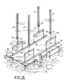
- FIG. 13 is a partial perspective view of the preferred embodiment of the apparatus of the present invention and showing a method step of the present invention
- FIG. 14 is an elevation view of the preferred embodiment of the apparatus of the present invention and illustrating the method of the present invention
- FIGS. 15-16 are elevation views that further illustrate the method of the present invention.
- FIG. 17 is a sectional view taken along lines 17 - 17 of FIG. 10 .
- FIGS. 1-7 and 9 - 11 show the preferred embodiment of the apparatus of the present invention designated generally by the numeral 10 .
- Marine lifting apparatus 10 provides a pair of spaced apart vessels or hulls 11 , 12 , each providing a deck 30 .
- Hulls 11 , 12 can be barges, dynamically positioned vessels, or any other buoyant structure.
- a pair of frames or trusses 13 , 14 are provided, each frame 13 , 14 spanning between the vessels 11 , 12 .
- Each frame 13 , 14 connects to one vessel 11 or 12 with a universal joint 15 or 17 (see FIGS. 1 , 4 , 9 ) and to the other hull 11 or 12 with a hinged or pinned connection 16 or 19 (see FIG. 4 ).
- the first frame 13 connects to hull 11 with universal joint 15 (or articulating connection).
- the first frame 13 connects to vessel 12 with a pinned connection or hinge 16 .
- the second frame 14 connects to hull 12 with a universal joint 17 (or articulating connection) and to hull 11 with a hinge or pinned connection 18 (see FIG. 4 ).
- An interface such as a deck beam or load spreader platform can be provided on the upper deck 30 of each hull 11 , 12 for forming an interface between the frames 13 , 14 and the vessels 11 , 12 .
- vessel 11 is provided with deck beam or load spreader platform 19 on its deck 30 that forms an interface between each of the frames 13 , 14 and the barge or vessel 11 deck 30 .
- Deck beam or load spreader platform 20 provides an interface between each of the frames 13 , 14 and deck 30 of the vessel or barge 12 .
- a lifting area 21 is that area that is in between the vessels 11 , 12 , the area 21 having a length defined by dimension arrow 23 and a width defined by dimension arrow 22 in FIG. 4 .
- This area 21 is sized and shaped to receive a vessel having a cargo to be lifted if that cargo (e.g. deck package) is to be installed.
- the area 21 can be an area that receives a vessel for supporting and transporting an item to be salvaged from an ocean floor (see FIGS. 5 and 11 - 15 ) such as a hurricane smashed or damaged offshore platform section 34 , sunken boat 33 or the like. In either case, a clearance is provided above the water surface 24 .
- a clearance between water surface 24 and frame 13 or 14 is indicated schematically by the dimension line 25 .
- a clearance 26 is provided above the maximum deck elevation 35 of the hulls 11 , 12 as shown in FIG. 3 .
- Each of the frames 13 , 14 can be in the form of a truss as shown.
- the frames are generally speaking in the shape of an arch or inverted U so that an area is provided under the frames and above the water surface for raising an item that is being salvaged or to lift an item from a barge or other vessel or support that is under the frames.
- Each truss or frame 13 , 14 can be a one piece structure (see FIG. 10 ) or a multi-section truss (see FIGS. 1-4 ).
- Pinned connections 31 , 32 can be provided for attaching the smaller truss sections 28 , 29 to the larger center truss section 27 as shown in FIGS. 3 and 4 .
- Slings can optionally be provided for connecting the center section 27 to the lower end portion of each of the smaller truss sections 28 , 29 .
- Shackles can be used to attach each of the slings to eyelets or padeyes on the center section 27 .
- shackles can be used to attach the slings to eyelets or padeyes on the smaller truss sections 28 , 29 .
- a hook 40 or other lifting fitting can be attached to a lifting line 41 and payed out from winch 42 . More than one lifting line 41 and hook 40 can be provided as shown. Sheaves 43 , 44 , 45 as needed can be used to route the line 41 from winch 42 to hook 40 .
- Line 41 can be a multiple line assembly to increase lift capacity such as is shown in FIG. 13 .
- Hook 40 can be any lifting fitting such as any known commercially available crown block, for example.
- FIGS. 6-9 illustrate the articulation that is achieved with the method and apparatus of the present invention, even in rough seas.
- FIGS. 6 and 7 rough sea conditions are shown wherein the vessels 11 , 12 assume differing orientations relative to each other caused by the rough sea state. Notwithstanding the orientation of the vessels 11 , 12 the combination of an articulating connection 15 , 17 with hinged or pinned connections 16 , 18 enables complete articulation between each of the frames or trusses 13 , 14 and each of the vessels or hulls 11 , 12 .
- FIGS. 9A-9D an exemplary articulating connection 15 , 17 is shown.
- a frame or truss 13 , 14 connects to a load spreader platform 19 or 20 at padeyes 61 , 62 .
- a first shaft 63 is pivotally attached to the padeyes 61 , 62 .
- a second shaft 64 is pivotally attached to the first shaft 63 at opening 69 in first shaft 63 .
- the second shaft 64 also defines a pivotal connection for the frame 13 or 14 to the first shaft 63 as shown.
- This universal joint arrangement enables the frame 13 (or 14 ) to move in an articulating fashion with respect to the load spreader platform 19 or 20 and with respect to the underlying vessel 11 or 12 as indicated schematically by arrows 65 , 66 in FIG. 9 .
- FIGS. 10-17 show the preferred embodiment of the apparatus of the present invention when fitted with a block and tackle arrangement.
- Vessels 11 , 12 are also shown fitted with anchor lines 67 that connect conventional anchors (not shown) to anchor winches 68 on the vessels 11 , 12 .
- the anchor winches 68 can be used to exactly position vessels 11 , 12 and to stabilize their positions during a lift.
- a block and tackle arrangement ( FIGS. 10-17 ) can be used to lift an item to be salvaged from the seabed 55 such as the damaged platform section 34 in FIG. 11 .
- each of the frames 13 , 14 is rigged with an upper sheave 48 and upper pulley block 49 .
- Each frame 13 or 14 can be rigged with a lifting line 41 and one or more winches 42 .
- each frame 13 , 14 has two winches 42 , each winch 42 having a lifting line or cable 41 .
- Lower pulley block 50 is positioned below upper pulley block 49 .
- the pulley blocks 49 , 50 can provide multiple pulleys such as is shown in FIGS. 10 , 13 and 17 .
- Slings 51 can be rigged to each lower pulley block 50 .
- Each sling 51 can support a lifting beam or spreader bar 54 .
- Each spreader bar 54 can support one or more slings 53 as shown in FIGS. 12 , 17 .
- the slings 53 can be provided with any selected additional rigging such as clamps, shackles or grabs 60 , as examples.
- Arrows 47 in FIG. 12 show lines 41 being payed out to lower the lower pulley blocks 50 to damaged platform section 34 (see arrow 56 , FIG. 12 ).
- the damaged platform section 34 to be salvaged can be fitted with beams 52 such as I-beams as an example.
- grabs 60 can be attached to the beams 52 with slings 53 as shown in FIG. 12 for a lifting operation.
- Arrow 56 in FIG. 12 schematically illustrates a lowering of the lower pulley blocks 50 to the sunken, damaged platform section 34 .
- arrow 57 in FIG. 14 schematically illustrates an elevating of the platform section 34 as each line 41 is wound upon its winch 42 .
- FIG. 15 the transport vessel 46 is moved into the area 21 under frames 12 , 13 , 14 .
- Arrow 58 schematically illustrates a lowering of the damaged platform section 34 to the vessel 46 .
- grabs 60 have been released from beams 52 and lifted upwardly in the direction of arrow 59 , away from the damaged platform section 34 .
- the damaged or salvaged item such as a vessel 33 or damaged platform section 34 can then be transported to a selected locale using the transport vessel or transport barge 46 .
- FIG. 11 an alternate load spreader platform construction is shown.
- a smaller load spreader platform 36 is placed under each universal joint 15 or 17 of the frame 13 or 14 .
- a larger load spreader platform 37 is placed under each pinned connection or hinge 16 or 18 of the frame 13 or 14 .
- Each platform 36 , 37 can comprise a plurality of longitudinal beams 38 and a plurality of transverse beams 39 as shown.
- the beams 38 , 39 can be structurally connected together (e.g. welded together).
- marine lifting apparatus 11 vessel 12 vessel 13 first frame or truss 14 second frame or truss 15 universal joint 16 hinge 17 universal joint 18 hinge 19 load spreader platform interface 20 load spreader platform interface 21 area 22 dimension line 23 dimension line 24 water surface 25 clearance above water 26 clearance above hull deck 27 center truss section 28 smaller truss section 29 smaller truss section 30 hull deck 31 pinned connection 32 pinned connection 33 sunken vessel 34 damaged platform section 35 maximum deck elevation 36 load spreader platform 37 load spreader platform 38 longitudinal beam 39 longitudinal beam 40 lifting hook 41 lifting line 42 winch 43 sheave 44 sheave 45 sheave 46 transport vessel 47 arrow 48 upper sheave 49 upper pulley block 50 lower pulley block 51 sling 52 beam 53 sling 54 spreader bar 55 seabed 56 arrow 57 arrow 58 arrow 59 arrow 60 grab 61 padeye 62 padeye 63 first shaft 64 second shaft 65 arrow 66 arrow 67 anchor line 68 anchor winch 69 opening
Landscapes
- Engineering & Computer Science (AREA)
- Mechanical Engineering (AREA)
- Ocean & Marine Engineering (AREA)
- Ship Loading And Unloading (AREA)
Abstract
Description
| TABLE 1 | ||
| PAT. NO. | TITLE | ISSUE DATE |
| 4,714,382 | Method and Apparatus for the Offshore | Dec. 22, 1987 |
| Installation of Multi-Ton Prefabricated | ||
| Deck Packages on Partially Submerged | ||
| Offshore Jacket Foundations | ||
| 5,607,260 | Method and Apparatus for the Offshore | Mar. 01, 1997 |
| Installation of Multi-Ton Prefabricated | ||
| Deck Packages on Partially Submerged | ||
| Offshore Jacket Foundations | ||
| 5,609,441 | Method and Apparatus for the Offshore | Mar. 11, 1997 |
| Installation of Multi-Ton Prefabricated | ||
| Deck Packages on Partially Submerged | ||
| Offshore Jacket Foundations | ||
| 5,662,434 | Method and Apparatus for the Offshore | Sep. 02, 1997 |
| Installation of Multi-Ton Prefabricated | ||
| Deck Packages on Partially Submerged | ||
| Offshore Jacket Foundations | ||
| 5,800,093 | Method and Apparatus for the Offshore | Sep. 01, 1998 |
| Installation of Multi-Ton Packages Such | ||
| as Deck Packages, Jackets, and Sunken | ||
| Vessels | ||
| 5,975,807 | Method and Apparatus for the Offshore | Nov. 02, 1999 |
| Installation of Multi-Ton Packages Such | ||
| as Deck Packages and Jackets | ||
| 6,039,506 | Method and Apparatus for the Offshore | Mar. 21, 2000 |
| Installation of Multi-Ton Packages Such | ||
| as Deck Packages and Jackets | ||
| 6,149,350 | Method and Apparatus for the Offshore | Nov. 21, 2000 |
| Installation of Multi-Ton Packages Such | ||
| as Deck Packages and Jackets | ||
| 6,318,931 | Method and Apparatus for the Offshore | Nov. 20, 2001 |
| Installation of Multi-Ton Packages Such | ||
| as Deck Packages and Jackets | ||
| 6,364,574 | Method and Apparatus for the Offshore | Apr. 02, 2002 |
| Installation of Multi-Ton Packages Such | ||
| as Deck Packages and Jackets | ||
| | Description | |
| 10 | |
|
| 11 | |
|
| 12 | |
|
| 13 | first frame or |
|
| 14 | second frame or |
|
| 15 | universal joint | |
| 16 | |
|
| 17 | universal joint | |
| 18 | |
|
| 19 | load |
|
| 20 | load |
|
| 21 | |
|
| 22 | |
|
| 23 | |
|
| 24 | |
|
| 25 | clearance above |
|
| 26 | clearance above |
|
| 27 | |
|
| 28 | |
|
| 29 | |
|
| 30 | |
|
| 31 | pinned |
|
| 32 | pinned |
|
| 33 | |
|
| 34 | damaged |
|
| 35 | |
|
| 36 | |
|
| 37 | |
|
| 38 | |
|
| 39 | |
|
| 40 | |
|
| 41 | |
|
| 42 | |
|
| 43 | |
|
| 44 | |
|
| 45 | |
|
| 46 | |
|
| 47 | |
|
| 48 | |
|
| 49 | |
|
| 50 | |
|
| 51 | |
|
| 52 | |
|
| 53 | |
|
| 54 | |
|
| 55 | |
|
| 56 | |
|
| 57 | |
|
| 58 | |
|
| 59 | |
|
| 60 | |
|
| 61 | |
|
| 62 | |
|
| 63 | |
|
| 64 | |
|
| 65 | |
|
| 66 | |
|
| 67 | |
|
| 68 | |
|
| 69 | opening | |
Claims (53)
Priority Applications (1)
| Application Number | Priority Date | Filing Date | Title |
|---|---|---|---|
| US12/435,134 US8061289B2 (en) | 2006-03-29 | 2009-05-04 | Marine lifting apparatus |
Applications Claiming Priority (3)
| Application Number | Priority Date | Filing Date | Title |
|---|---|---|---|
| US74391706P | 2006-03-29 | 2006-03-29 | |
| US11/610,271 US7527006B2 (en) | 2006-03-29 | 2006-12-13 | Marine lifting apparatus |
| US12/435,134 US8061289B2 (en) | 2006-03-29 | 2009-05-04 | Marine lifting apparatus |
Related Parent Applications (1)
| Application Number | Title | Priority Date | Filing Date |
|---|---|---|---|
| US11/610,271 Continuation US7527006B2 (en) | 2006-03-29 | 2006-12-13 | Marine lifting apparatus |
Publications (2)
| Publication Number | Publication Date |
|---|---|
| US20090301372A1 US20090301372A1 (en) | 2009-12-10 |
| US8061289B2 true US8061289B2 (en) | 2011-11-22 |
Family
ID=39536923
Family Applications (2)
| Application Number | Title | Priority Date | Filing Date |
|---|---|---|---|
| US11/610,271 Active US7527006B2 (en) | 2006-03-29 | 2006-12-13 | Marine lifting apparatus |
| US12/435,134 Active US8061289B2 (en) | 2006-03-29 | 2009-05-04 | Marine lifting apparatus |
Family Applications Before (1)
| Application Number | Title | Priority Date | Filing Date |
|---|---|---|---|
| US11/610,271 Active US7527006B2 (en) | 2006-03-29 | 2006-12-13 | Marine lifting apparatus |
Country Status (5)
| Country | Link |
|---|---|
| US (2) | US7527006B2 (en) |
| EP (1) | EP2089268B1 (en) |
| CA (1) | CA2672548C (en) |
| DK (1) | DK2089268T3 (en) |
| WO (1) | WO2008076462A2 (en) |
Cited By (17)
| Publication number | Priority date | Publication date | Assignee | Title |
|---|---|---|---|---|
| US20110197799A1 (en) * | 2007-12-17 | 2011-08-18 | Jon Khachaturian | Marine lifting apparatus |
| US20110203507A1 (en) * | 2008-10-28 | 2011-08-25 | Piet Ellnor | Ocean going transport vessel with docking arrangements |
| US20110236174A1 (en) * | 2008-05-20 | 2011-09-29 | Fred Francis Escher | Floating vessel for servicing air diffusers |
| WO2011133876A2 (en) | 2010-04-22 | 2011-10-27 | Alnylam Pharmaceuticals, Inc. | Oligonucleotides comprising acyclic and abasic nucleosides and analogs |
| WO2011133868A2 (en) | 2010-04-22 | 2011-10-27 | Alnylam Pharmaceuticals, Inc. | Conformationally restricted dinucleotide monomers and oligonucleotides |
| US20120266804A1 (en) * | 2011-04-22 | 2012-10-25 | Stx France S.A. | Passenger ship of which the superstructure is equipped with at least one arch |
| US20130071207A1 (en) * | 2011-09-20 | 2013-03-21 | Technip France | Quick release system for topsides float-over installation on offshore platforms |
| US8960114B2 (en) | 2010-11-30 | 2015-02-24 | Jon Khachaturian | Marine lifting apparatus |
| US20150259053A1 (en) * | 2006-03-29 | 2015-09-17 | Jon Khachaturian | Marine lifting apparatus |
| US9138817B1 (en) | 2012-09-17 | 2015-09-22 | Jon Khachaturian | Method and apparatus for removing underwater platforms |
| US9446825B1 (en) | 2013-12-10 | 2016-09-20 | Hugh Francis Gallagher | Self-propelled, catamaran-type, dual-application, semisubmersible ship with hydrodynamic hulls and columns |
| US10279872B2 (en) | 2015-10-16 | 2019-05-07 | Versabar, Inc. | Floating catamaran production platform |
| US10486779B2 (en) | 2015-10-16 | 2019-11-26 | Versabar, Inc. | Floating catamaran production platform |
| US11492080B1 (en) | 2019-08-26 | 2022-11-08 | Jon Khachaturian | Method and apparatus for unloading cargo in an offshore marine environment |
| US12172737B2 (en) | 2022-06-11 | 2024-12-24 | Hugh Francis Gallagher | Semi-autonomous immersible waterborne dock enclosure |
| US12473060B2 (en) | 2006-03-29 | 2025-11-18 | Gatorfur, Llc | Marine lifting apparatus |
| US12584461B2 (en) | 2022-09-08 | 2026-03-24 | Jason C. FABRE | Floating offshore wind turbine apparatus and installation method |
Families Citing this family (35)
| Publication number | Priority date | Publication date | Assignee | Title |
|---|---|---|---|---|
| US7527006B2 (en) * | 2006-03-29 | 2009-05-05 | Jon Khachaturian | Marine lifting apparatus |
| ATE409279T1 (en) * | 2006-07-14 | 2008-10-15 | Openhydro Group Ltd | TURBINES WITH A SLIDE FOR THE FLOW OF FOREIGN BODY |
| EP1878913B1 (en) * | 2006-07-14 | 2013-03-13 | OpenHydro Group Limited | Bi-directional tidal flow hydroelectric turbine |
| DE602007001582D1 (en) * | 2007-04-11 | 2009-08-27 | Openhydro Group Ltd | Method for installing a hydroelectric turbine |
| EP1980746B2 (en) | 2007-04-11 | 2013-08-07 | OpenHydro Group Limited | A method of installing a hydroelectric turbine |
| WO2009070034A2 (en) * | 2007-11-26 | 2009-06-04 | Subsea 7 Norway Nuf | Method for picking up and towing a structure under water |
| ATE480035T1 (en) * | 2007-12-12 | 2010-09-15 | Openhydro Group Ltd | GENERATOR COMPONENT FOR A HYDROELECTRIC TURBINE |
| US20100263581A1 (en) * | 2007-12-17 | 2010-10-21 | Jon Khachaturian | Marine Lifting Apparatus |
| US12522329B2 (en) | 2007-12-17 | 2026-01-13 | Gatorfur, Llc | Marine lifting apparatus |
| BRPI0800075A2 (en) * | 2008-02-01 | 2009-10-20 | Zytech Industrial Ltda | auxiliary floating structure and process for descending equipment overboard |
| BRPI0800140A2 (en) * | 2008-02-01 | 2009-10-20 | Zytech Industrial Ltda | process for lowering equipment to the bottom of the sea |
| EP2088311B1 (en) | 2008-02-05 | 2015-10-14 | OpenHydro Group Limited | A hydroelectric turbine with floating rotor |
| EP2110910A1 (en) | 2008-04-17 | 2009-10-21 | OpenHydro Group Limited | An improved turbine installation method |
| US20110094427A1 (en) * | 2008-12-16 | 2011-04-28 | Burns Mark L | Fast jack hybrid liftboat hull |
| EP2199598B1 (en) | 2008-12-18 | 2012-05-02 | OpenHydro IP Limited | A hydroelectric turbine comprising a passive brake and method of operation |
| DE602008002602D1 (en) | 2008-12-19 | 2010-10-28 | Openhydro Ip Ltd | Method for installing a hydroelectric turbine generator |
| RU2382731C1 (en) * | 2009-02-17 | 2010-02-27 | Виктор Валентинович Занченко | Floating crane |
| ATE548562T1 (en) | 2009-04-17 | 2012-03-15 | Openhydro Ip Ltd | IMPROVED METHOD FOR CONTROLLING THE OUTPUT OF A HYDROELECTRIC TURBINE GENERATOR |
| EP2302766B1 (en) | 2009-09-29 | 2013-03-13 | OpenHydro IP Limited | A hydroelectric turbine with coil cooling |
| EP2302755B1 (en) | 2009-09-29 | 2012-11-28 | OpenHydro IP Limited | An electrical power conversion system and method |
| EP2302204A1 (en) | 2009-09-29 | 2011-03-30 | OpenHydro IP Limited | A hydroelectric turbine system |
| MX2012011928A (en) | 2010-04-14 | 2013-05-09 | Jon Khachaturian | Marine lifting apparatus. |
| MY166840A (en) | 2010-09-22 | 2018-07-24 | Jon E Khachaturian | Articulated multiple buoy marine platform apparatus and method of installation |
| EP2450562B1 (en) | 2010-11-09 | 2015-06-24 | Openhydro IP Limited | A hydroelectric turbine recovery system and a method therefore |
| EP2469257B1 (en) | 2010-12-23 | 2014-02-26 | Openhydro IP Limited | A hydroelectric turbine testing method |
| US8826839B2 (en) * | 2011-08-30 | 2014-09-09 | Horton do Brasil Technologia Offshore, Ltda | Methods and systems for FPSO deck mating |
| AU2014342198A1 (en) * | 2013-10-31 | 2016-05-05 | Jon Khachaturian | Method and apparatus for removing underwater platforms |
| JP6154921B1 (en) * | 2016-01-15 | 2017-06-28 | 日綜産業株式会社 | Gondola for blade maintenance in wind power generators |
| US10184587B1 (en) * | 2016-04-28 | 2019-01-22 | Versabar, Inc. | Underwater pipe lifting and cutting apparatus and method |
| CN108045514B (en) * | 2017-12-08 | 2023-10-20 | 中国铁建港航局集团有限公司 | Fishing device for bridge construction |
| CN113582037B (en) * | 2021-09-28 | 2021-11-30 | 江苏海通海洋工程装备有限公司 | Large barge hoisting and launching method based on different-tonnage double gantry cranes |
| CN114750899B (en) * | 2022-04-12 | 2023-06-30 | 交通运输部上海打捞局 | Method for assembling end plate top beam assembly of sunken ship integral salvaging equipment |
| CN115679831B (en) * | 2022-11-14 | 2025-06-17 | 中铁四局集团第二工程有限公司 | A trestle construction method using ship-assisted construction |
| CN116623738A (en) * | 2023-04-25 | 2023-08-22 | 浙江大学 | Full-section excavated end plate suitable for underwater salvage equipment and sinking method thereof |
| US20250223018A1 (en) * | 2024-01-08 | 2025-07-10 | Bardex Corporation | Modular launch and recovery platform |
Citations (31)
| Publication number | Priority date | Publication date | Assignee | Title |
|---|---|---|---|---|
| US2378A (en) * | 1841-12-10 | Machinery foe | ||
| US485398A (en) | 1892-11-01 | tyler | ||
| US541794A (en) | 1895-06-25 | Fifths to anton lutz and george muth | ||
| US1659647A (en) | 1927-01-14 | 1928-02-21 | Althouse Robert Mcallister | Sea crane |
| US3645405A (en) | 1970-04-20 | 1972-02-29 | Eness Research & Dev Corp | Cargo-handling vessel |
| US3807336A (en) | 1972-09-13 | 1974-04-30 | H Briggs | Structure for salvaging sunken ships |
| US4385583A (en) | 1980-10-16 | 1983-05-31 | Shell Oil Company | Work platform |
| JPS58122694A (en) | 1982-01-18 | 1983-07-21 | Toshiba Corp | Storage device |
| US4714382A (en) | 1985-05-14 | 1987-12-22 | Khachaturian Jon E | Method and apparatus for the offshore installation of multi-ton prefabricated deck packages on partially submerged offshore jacket foundations |
| US5054415A (en) | 1987-03-11 | 1991-10-08 | Marshall Industries Limited | Mooring/support system for marine structures |
| US5607260A (en) | 1995-03-15 | 1997-03-04 | Khachaturian; Jon E. | Method and apparatus for the offshore installation of multi-ton prefabricated deck packages on partially submerged offshore jacket foundations |
| US5662434A (en) | 1995-03-15 | 1997-09-02 | Khachaturian; Jon E. | Method and apparatus for the offshore installation of multi-ton prefabricated deck packages on partially submerged offshore jacket foundations |
| US5800093A (en) | 1995-03-15 | 1998-09-01 | Khachaturian; Jon E. | Method and apparatus for the offshore installation of multi-ton packages such as deck packages, jackets, and sunken vessels |
| US5836463A (en) | 1996-12-09 | 1998-11-17 | Khachaturian; Jon E. | Powered lifting apparatus using multiple booms |
| US5863085A (en) | 1996-09-23 | 1999-01-26 | Versabar, Inc. | Spreader bar assembly |
| WO1999013164A1 (en) | 1997-09-08 | 1999-03-18 | Khachaturian Jon E | Method and apparatus for the offshore installation of multi-ton packages such as deck packages and jackets |
| US5975807A (en) | 1995-03-15 | 1999-11-02 | Khachaturian; Jon E. | Method and apparatus for the offshore installation of multi-ton packages such as deck packages and jackets |
| US6079760A (en) | 1996-09-23 | 2000-06-27 | Khachaturian; Jon E. | Spreader bar apparatus |
| US6149350A (en) | 1995-03-15 | 2000-11-21 | Khachaturian; Jon E. | Method and apparatus for the offshore installation of multi-ton packages such as deck packages and jackets |
| US6318931B1 (en) | 1995-03-15 | 2001-11-20 | Jon E. Khachaturian | Method and apparatus for the offshore installation of multi-ton packages such as deck packages and jackets |
| US6367399B1 (en) | 1995-03-15 | 2002-04-09 | Jon E. Khachaturian | Method and apparatus for modifying new or existing marine platforms |
| US6412649B1 (en) | 2000-02-07 | 2002-07-02 | Jon E. Khachaturian | Spreader bar apparatus |
| US6425710B1 (en) | 2000-06-21 | 2002-07-30 | Jon Khachaturian | Articulated multiple buoy marine platform apparatus |
| US6601717B1 (en) | 1996-12-09 | 2003-08-05 | Jon Khachaturian | Powered lifting apparatus using multiple booms |
| US6719495B2 (en) | 2000-06-21 | 2004-04-13 | Jon E. Khachaturian | Articulated multiple buoy marine platform apparatus and method of installation |
| US7066343B1 (en) | 1996-12-09 | 2006-06-27 | Khachaturian Jon E | Powered lifting apparatus using multiple booms |
| US7399018B1 (en) | 2003-05-15 | 2008-07-15 | Khachaturian Jon E | Lifting sling |
| US7527006B2 (en) * | 2006-03-29 | 2009-05-05 | Jon Khachaturian | Marine lifting apparatus |
| KR20100008652A (en) | 2008-07-16 | 2010-01-26 | 인천대학교 산학협력단 | A manless vessel system using catamaram |
| US7845296B1 (en) | 2006-12-13 | 2010-12-07 | Jon Khachaturian | Marine lifting apparatus |
| US7886676B2 (en) | 2007-12-17 | 2011-02-15 | Jon Khachaturian | Marine lifting apparatus |
Family Cites Families (1)
| Publication number | Priority date | Publication date | Assignee | Title |
|---|---|---|---|---|
| US2916002A (en) * | 1957-04-26 | 1959-12-08 | William A Hunsucker | Marine hoisting apparatus |
-
2006
- 2006-12-13 US US11/610,271 patent/US7527006B2/en active Active
-
2007
- 2007-05-10 EP EP07783599.9A patent/EP2089268B1/en active Active
- 2007-05-10 CA CA2672548A patent/CA2672548C/en active Active
- 2007-05-10 WO PCT/US2007/068689 patent/WO2008076462A2/en not_active Ceased
- 2007-05-10 DK DK07783599.9T patent/DK2089268T3/en active
-
2009
- 2009-05-04 US US12/435,134 patent/US8061289B2/en active Active
Patent Citations (41)
| Publication number | Priority date | Publication date | Assignee | Title |
|---|---|---|---|---|
| US2378A (en) * | 1841-12-10 | Machinery foe | ||
| US485398A (en) | 1892-11-01 | tyler | ||
| US541794A (en) | 1895-06-25 | Fifths to anton lutz and george muth | ||
| US1659647A (en) | 1927-01-14 | 1928-02-21 | Althouse Robert Mcallister | Sea crane |
| US3645405A (en) | 1970-04-20 | 1972-02-29 | Eness Research & Dev Corp | Cargo-handling vessel |
| US3807336A (en) | 1972-09-13 | 1974-04-30 | H Briggs | Structure for salvaging sunken ships |
| US4385583A (en) | 1980-10-16 | 1983-05-31 | Shell Oil Company | Work platform |
| JPS58122694A (en) | 1982-01-18 | 1983-07-21 | Toshiba Corp | Storage device |
| US4714382A (en) | 1985-05-14 | 1987-12-22 | Khachaturian Jon E | Method and apparatus for the offshore installation of multi-ton prefabricated deck packages on partially submerged offshore jacket foundations |
| US5054415A (en) | 1987-03-11 | 1991-10-08 | Marshall Industries Limited | Mooring/support system for marine structures |
| US5607260A (en) | 1995-03-15 | 1997-03-04 | Khachaturian; Jon E. | Method and apparatus for the offshore installation of multi-ton prefabricated deck packages on partially submerged offshore jacket foundations |
| US5609441A (en) | 1995-03-15 | 1997-03-11 | Khachaturian; Jon E. | Method and apparatus for the offshore installation of multi-ton prefabricated deck packages on partially submerged offshore jacket foundations |
| US5662434A (en) | 1995-03-15 | 1997-09-02 | Khachaturian; Jon E. | Method and apparatus for the offshore installation of multi-ton prefabricated deck packages on partially submerged offshore jacket foundations |
| US5800093A (en) | 1995-03-15 | 1998-09-01 | Khachaturian; Jon E. | Method and apparatus for the offshore installation of multi-ton packages such as deck packages, jackets, and sunken vessels |
| US6367399B1 (en) | 1995-03-15 | 2002-04-09 | Jon E. Khachaturian | Method and apparatus for modifying new or existing marine platforms |
| US6364574B1 (en) | 1995-03-15 | 2002-04-02 | Jon E. Khachaturian | Method and apparatus for the offshore installation of multi-ton packages such as deck packages and jackets |
| US6318931B1 (en) | 1995-03-15 | 2001-11-20 | Jon E. Khachaturian | Method and apparatus for the offshore installation of multi-ton packages such as deck packages and jackets |
| US5975807A (en) | 1995-03-15 | 1999-11-02 | Khachaturian; Jon E. | Method and apparatus for the offshore installation of multi-ton packages such as deck packages and jackets |
| US6149350A (en) | 1995-03-15 | 2000-11-21 | Khachaturian; Jon E. | Method and apparatus for the offshore installation of multi-ton packages such as deck packages and jackets |
| US6079760A (en) | 1996-09-23 | 2000-06-27 | Khachaturian; Jon E. | Spreader bar apparatus |
| US5863085A (en) | 1996-09-23 | 1999-01-26 | Versabar, Inc. | Spreader bar assembly |
| US6000562A (en) | 1996-12-09 | 1999-12-14 | Khachaturian; Jon E. | Powered lifting apparatus using multiple booms |
| US6213319B1 (en) | 1996-12-09 | 2001-04-10 | Jon E. Khachaturian | Powered lifting apparatus using multiple booms |
| US5836463A (en) | 1996-12-09 | 1998-11-17 | Khachaturian; Jon E. | Powered lifting apparatus using multiple booms |
| US7066343B1 (en) | 1996-12-09 | 2006-06-27 | Khachaturian Jon E | Powered lifting apparatus using multiple booms |
| US6601717B1 (en) | 1996-12-09 | 2003-08-05 | Jon Khachaturian | Powered lifting apparatus using multiple booms |
| US6039506A (en) | 1997-09-08 | 2000-03-21 | Khachaturian; Jon E. | Method and apparatus for the offshore installation of multi-ton packages such as deck packages and jackets |
| WO1999013164A1 (en) | 1997-09-08 | 1999-03-18 | Khachaturian Jon E | Method and apparatus for the offshore installation of multi-ton packages such as deck packages and jackets |
| US6296288B1 (en) | 1998-06-25 | 2001-10-02 | Jon E. Khachaturian | Spreader bar apparatus |
| US6412649B1 (en) | 2000-02-07 | 2002-07-02 | Jon E. Khachaturian | Spreader bar apparatus |
| US6435774B1 (en) | 2000-06-21 | 2002-08-20 | Jon Khachaturian | Articulated multiple buoy marine platform apparatus |
| US6435773B1 (en) | 2000-06-21 | 2002-08-20 | Jon Khachaturian | Articulated multiple buoy marine platform apparatus and method of installation |
| US6692190B2 (en) | 2000-06-21 | 2004-02-17 | Jon Khachaturian | Articulated multiple buoy marine platform apparatus |
| US6719495B2 (en) | 2000-06-21 | 2004-04-13 | Jon E. Khachaturian | Articulated multiple buoy marine platform apparatus and method of installation |
| US6425710B1 (en) | 2000-06-21 | 2002-07-30 | Jon Khachaturian | Articulated multiple buoy marine platform apparatus |
| US7399018B1 (en) | 2003-05-15 | 2008-07-15 | Khachaturian Jon E | Lifting sling |
| US7527006B2 (en) * | 2006-03-29 | 2009-05-05 | Jon Khachaturian | Marine lifting apparatus |
| US20090301372A1 (en) | 2006-03-29 | 2009-12-10 | Jon Khachaturian | Marine lifting apparatus |
| US7845296B1 (en) | 2006-12-13 | 2010-12-07 | Jon Khachaturian | Marine lifting apparatus |
| US7886676B2 (en) | 2007-12-17 | 2011-02-15 | Jon Khachaturian | Marine lifting apparatus |
| KR20100008652A (en) | 2008-07-16 | 2010-01-26 | 인천대학교 산학협력단 | A manless vessel system using catamaram |
Cited By (32)
| Publication number | Priority date | Publication date | Assignee | Title |
|---|---|---|---|---|
| US12473060B2 (en) | 2006-03-29 | 2025-11-18 | Gatorfur, Llc | Marine lifting apparatus |
| US11345452B2 (en) | 2006-03-29 | 2022-05-31 | Versabar, Inc. | Marine lifting apparatus |
| US10543890B2 (en) | 2006-03-29 | 2020-01-28 | Versabar, Inc. | Marine lifting apparatus |
| US9604710B2 (en) * | 2006-03-29 | 2017-03-28 | Jon Khachaturian | Marine lifting apparatus |
| US20150259053A1 (en) * | 2006-03-29 | 2015-09-17 | Jon Khachaturian | Marine lifting apparatus |
| US20110197799A1 (en) * | 2007-12-17 | 2011-08-18 | Jon Khachaturian | Marine lifting apparatus |
| US8240264B2 (en) * | 2007-12-17 | 2012-08-14 | Jon Khachaturian | Marine lifting apparatus |
| US8522705B2 (en) * | 2008-05-20 | 2013-09-03 | Fred Francis Escher | Floating vessel for servicing air diffusers |
| US20110236174A1 (en) * | 2008-05-20 | 2011-09-29 | Fred Francis Escher | Floating vessel for servicing air diffusers |
| US8739717B2 (en) | 2008-10-28 | 2014-06-03 | Piet Ellnor | Ocean going transport vessel with docking arrangements |
| US20110203507A1 (en) * | 2008-10-28 | 2011-08-25 | Piet Ellnor | Ocean going transport vessel with docking arrangements |
| WO2011133876A2 (en) | 2010-04-22 | 2011-10-27 | Alnylam Pharmaceuticals, Inc. | Oligonucleotides comprising acyclic and abasic nucleosides and analogs |
| WO2011133868A2 (en) | 2010-04-22 | 2011-10-27 | Alnylam Pharmaceuticals, Inc. | Conformationally restricted dinucleotide monomers and oligonucleotides |
| US9701376B2 (en) | 2010-11-30 | 2017-07-11 | Jon Khachaturian | Marine lifting apparatus |
| US10286985B2 (en) | 2010-11-30 | 2019-05-14 | Versabar, Inc. | Marine lifting apparatus |
| US8960114B2 (en) | 2010-11-30 | 2015-02-24 | Jon Khachaturian | Marine lifting apparatus |
| US10960959B2 (en) | 2010-11-30 | 2021-03-30 | Versabar, Inc. | Marine lifting apparatus |
| US8939101B2 (en) * | 2011-04-22 | 2015-01-27 | Stx France S.A. | Passenger ship of which the superstructure is equipped with at least one arch |
| US20120266804A1 (en) * | 2011-04-22 | 2012-10-25 | Stx France S.A. | Passenger ship of which the superstructure is equipped with at least one arch |
| US20130071207A1 (en) * | 2011-09-20 | 2013-03-21 | Technip France | Quick release system for topsides float-over installation on offshore platforms |
| US8708604B2 (en) * | 2011-09-20 | 2014-04-29 | Technip France | Quick release system for topsides float-over installation on offshore platforms |
| US9138817B1 (en) | 2012-09-17 | 2015-09-22 | Jon Khachaturian | Method and apparatus for removing underwater platforms |
| US10471526B2 (en) | 2012-09-17 | 2019-11-12 | Versabar, Inc. | Method and apparatus for removing underwater platforms |
| US9808873B2 (en) | 2012-09-17 | 2017-11-07 | Jon Khachaturian | Method and apparatus for removing underwater platforms |
| US9446825B1 (en) | 2013-12-10 | 2016-09-20 | Hugh Francis Gallagher | Self-propelled, catamaran-type, dual-application, semisubmersible ship with hydrodynamic hulls and columns |
| US10486779B2 (en) | 2015-10-16 | 2019-11-26 | Versabar, Inc. | Floating catamaran production platform |
| US10279872B2 (en) | 2015-10-16 | 2019-05-07 | Versabar, Inc. | Floating catamaran production platform |
| US11034416B2 (en) | 2015-10-16 | 2021-06-15 | Versabar, Inc. | Floating catamaran production platform |
| US11034417B2 (en) | 2015-10-16 | 2021-06-15 | Versabar, Inc. | Floating catamaran production platform |
| US11492080B1 (en) | 2019-08-26 | 2022-11-08 | Jon Khachaturian | Method and apparatus for unloading cargo in an offshore marine environment |
| US12172737B2 (en) | 2022-06-11 | 2024-12-24 | Hugh Francis Gallagher | Semi-autonomous immersible waterborne dock enclosure |
| US12584461B2 (en) | 2022-09-08 | 2026-03-24 | Jason C. FABRE | Floating offshore wind turbine apparatus and installation method |
Also Published As
| Publication number | Publication date |
|---|---|
| US20090301372A1 (en) | 2009-12-10 |
| CA2672548C (en) | 2013-10-08 |
| US7527006B2 (en) | 2009-05-05 |
| EP2089268B1 (en) | 2016-04-06 |
| EP2089268A2 (en) | 2009-08-19 |
| EP2089268A4 (en) | 2012-10-10 |
| US20070231076A1 (en) | 2007-10-04 |
| DK2089268T3 (en) | 2016-04-18 |
| CA2672548A1 (en) | 2008-06-26 |
| WO2008076462A2 (en) | 2008-06-26 |
| WO2008076462A3 (en) | 2008-08-28 |
Similar Documents
| Publication | Publication Date | Title |
|---|---|---|
| US11345452B2 (en) | Marine lifting apparatus | |
| US8061289B2 (en) | Marine lifting apparatus | |
| US7845296B1 (en) | Marine lifting apparatus | |
| US11479329B2 (en) | Marine lifting apparatus | |
| US10960959B2 (en) | Marine lifting apparatus | |
| US8240264B2 (en) | Marine lifting apparatus | |
| US20250214690A1 (en) | Marine lifting apparatus | |
| US12473060B2 (en) | Marine lifting apparatus | |
| MX2007003760A (en) | Marine lifting apparatus. |
Legal Events
| Date | Code | Title | Description |
|---|---|---|---|
| STCF | Information on status: patent grant |
Free format text: PATENTED CASE |
|
| FPAY | Fee payment |
Year of fee payment: 4 |
|
| AS | Assignment |
Owner name: WELLS FARGO BANK, NATIONAL ASSOCIATION, NORTH CARO Free format text: SECURITY INTEREST;ASSIGNOR:VERSABAR, INC.;REEL/FRAME:042945/0055 Effective date: 20170615 |
|
| AS | Assignment |
Owner name: VERSABAR, INC., TEXAS Free format text: ASSIGNMENT OF ASSIGNORS INTEREST;ASSIGNOR:KHACHATURIAN, JON E.;REEL/FRAME:043572/0098 Effective date: 20170615 |
|
| MAFP | Maintenance fee payment |
Free format text: PAYMENT OF MAINTENANCE FEE, 8TH YR, SMALL ENTITY (ORIGINAL EVENT CODE: M2552); ENTITY STATUS OF PATENT OWNER: SMALL ENTITY Year of fee payment: 8 |
|
| MAFP | Maintenance fee payment |
Free format text: PAYMENT OF MAINTENANCE FEE, 12TH YR, SMALL ENTITY (ORIGINAL EVENT CODE: M2553); ENTITY STATUS OF PATENT OWNER: SMALL ENTITY Year of fee payment: 12 |
|
| AS | Assignment |
Owner name: MC51, LLC, TEXAS Free format text: ASSIGNMENT OF SECURITY INTEREST;ASSIGNOR:WELLS FARGO BANK, NATIONAL ASSOCIATION;REEL/FRAME:067077/0781 Effective date: 20210311 |
|
| AS | Assignment |
Owner name: VERSABAR, INC., TEXAS Free format text: RELEASE BY SECURED PARTY;ASSIGNOR:MC51, LLC;REEL/FRAME:067381/0630 Effective date: 20240418 Owner name: VERSABAR, INC., TEXAS Free format text: RELEASE OF SECURITY INTEREST;ASSIGNOR:MC51, LLC;REEL/FRAME:067381/0630 Effective date: 20240418 |
|
| AS | Assignment |
Owner name: GATORFUR, LLC, TEXAS Free format text: ASSIGNMENT OF ASSIGNORS INTEREST;ASSIGNOR:VERSABAR, INC.;REEL/FRAME:067571/0487 Effective date: 20240419 |