US8059719B2 - Adaptive area of influence filter - Google Patents
Adaptive area of influence filter Download PDFInfo
- Publication number
- US8059719B2 US8059719B2 US11/229,284 US22928405A US8059719B2 US 8059719 B2 US8059719 B2 US 8059719B2 US 22928405 A US22928405 A US 22928405A US 8059719 B2 US8059719 B2 US 8059719B2
- Authority
- US
- United States
- Prior art keywords
- pixel
- motion vector
- area
- filter
- cell
- Prior art date
- Legal status (The legal status is an assumption and is not a legal conclusion. Google has not performed a legal analysis and makes no representation as to the accuracy of the status listed.)
- Expired - Fee Related, expires
Links
Images


Classifications
-
- H—ELECTRICITY
- H04—ELECTRIC COMMUNICATION TECHNIQUE
- H04N—PICTORIAL COMMUNICATION, e.g. TELEVISION
- H04N19/00—Methods or arrangements for coding, decoding, compressing or decompressing digital video signals
- H04N19/50—Methods or arrangements for coding, decoding, compressing or decompressing digital video signals using predictive coding
- H04N19/503—Methods or arrangements for coding, decoding, compressing or decompressing digital video signals using predictive coding involving temporal prediction
- H04N19/51—Motion estimation or motion compensation
- H04N19/513—Processing of motion vectors
- H04N19/521—Processing of motion vectors for estimating the reliability of the determined motion vectors or motion vector field, e.g. for smoothing the motion vector field or for correcting motion vectors
-
- H—ELECTRICITY
- H04—ELECTRIC COMMUNICATION TECHNIQUE
- H04N—PICTORIAL COMMUNICATION, e.g. TELEVISION
- H04N19/00—Methods or arrangements for coding, decoding, compressing or decompressing digital video signals
- H04N19/10—Methods or arrangements for coding, decoding, compressing or decompressing digital video signals using adaptive coding
- H04N19/102—Methods or arrangements for coding, decoding, compressing or decompressing digital video signals using adaptive coding characterised by the element, parameter or selection affected or controlled by the adaptive coding
- H04N19/117—Filters, e.g. for pre-processing or post-processing
-
- H—ELECTRICITY
- H04—ELECTRIC COMMUNICATION TECHNIQUE
- H04N—PICTORIAL COMMUNICATION, e.g. TELEVISION
- H04N19/00—Methods or arrangements for coding, decoding, compressing or decompressing digital video signals
- H04N19/10—Methods or arrangements for coding, decoding, compressing or decompressing digital video signals using adaptive coding
- H04N19/169—Methods or arrangements for coding, decoding, compressing or decompressing digital video signals using adaptive coding characterised by the coding unit, i.e. the structural portion or semantic portion of the video signal being the object or the subject of the adaptive coding
- H04N19/182—Methods or arrangements for coding, decoding, compressing or decompressing digital video signals using adaptive coding characterised by the coding unit, i.e. the structural portion or semantic portion of the video signal being the object or the subject of the adaptive coding the unit being a pixel
-
- H—ELECTRICITY
- H04—ELECTRIC COMMUNICATION TECHNIQUE
- H04N—PICTORIAL COMMUNICATION, e.g. TELEVISION
- H04N19/00—Methods or arrangements for coding, decoding, compressing or decompressing digital video signals
- H04N19/50—Methods or arrangements for coding, decoding, compressing or decompressing digital video signals using predictive coding
- H04N19/503—Methods or arrangements for coding, decoding, compressing or decompressing digital video signals using predictive coding involving temporal prediction
- H04N19/51—Motion estimation or motion compensation
- H04N19/513—Processing of motion vectors
Definitions
- the invention is related to the field of video compression.
- a temporal prediction filter is used in a video compression process to predict a target image from a set of previously decoded reference images.
- the temporal prediction process is effective at removing a significant amount of temporal redundancy, which generally results in a higher coding efficiency.
- the prediction process uses a set of motion vectors and a filter that operates on the motion vectors to predict the target image.
- the prediction method divides a reference image 110 into multiple fixed-size blocks 120 , as shown in FIG. 1 .
- Each block has an associated motion vector to describe the motion of the block relative to the target image.
- the motion vectors are shown by the white dots in image 110 .
- a temporal prediction filter uses the associated motion vector to perform a simple motion compensation technique on each block in the reference image to predict the location of the block in the target image.
- each block in the target image is estimated from a block in the reference image using the single motion vector.
- this approach treats each motion vector independently and is not adaptive to image features.
- a method of generating an adaptive temporal filter is performed by constructing a motion vector area cell around each of a plurality of motion vectors in a target image, selecting a pixel in the target image, constructing a pixel area cell around the selected pixel, determining an overlap area between the motion vector area cells and the pixel area cell, generating filter weights from the overlap area, and using the filter weights to filter the selected pixel.
- FIG. 1 shows an example of a conventional block based temporal filter.
- FIG. 2 shows an example of an adaptive temporal filtering procedure.
- FIG. 3 shows examples of an irregular pattern of motion vectors and area of influence cells used in the adaptive temporal filtering procedure.
- FIGS. 4A and 4B show examples of a method to generate an adaptive temporal filter used in the adaptive temporal filtering procedure.
- FIG. 5 shows an example of a prediction performed with the adaptive temporal filter.
- FIG. 6 shows an example of an error reduction method which can be used in the adaptive temporal filtering procedure.
- FIG. 7 shows an example of a video compression encoding process that uses the adaptive temporal filter.
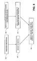
- FIG. 8 shows an example of a decoding process that uses the adaptive temporal filter.
- FIG. 9 shows an example of a system that uses the adaptive area of influence filter.
- An adaptive area of influence (AAOI) temporal filter automatically adapts to an irregular pattern of motion vectors, object features, and spatial textures when predicting a target image.
- the AAOI filter operates in the time-domain over motion compensated signals, which is different from other methods that attempt to filter motion vectors directly (e.g., triangulation filtering in the motion vector domain). For example, because the AAOI filtering method operates in the time-domain, it is more amenable to adaptation to object and spatial textures.
- the AAOI filter performs a two stage process to couple neighboring motion vectors during the prediction of a pixel. The first stage adapts the filter to an irregular sampling pattern of motion vectors, to object shapes, and to boundaries. The second stage adapts the filter to spatial textures of the image.
- FIG. 2 An example of an adaptive temporal filtering procedure is shown in FIG. 2 .
- an irregular sampling pattern of motion vectors is generated for an image. Such irregular patterning may be done in various ways using methods that are known to those of skill in the art.
- An example of an irregular pattern of motion vectors is shown in block 310 of FIG. 3 .
- the white dots in the image 310 represent the motion vectors.
- the motion vectors are more concentrated in regions that are difficult to predict from the reference image (i.e., image regions with more complex motion, such as regions near moving boundaries). Fewer motion vectors are placed in simple motion regions, such as image background regions, for example.
- each AOI cell has one motion vector as its node.
- An example of an image partitioned into AOI cells is shown in FIG. 3 , at block 320 .
- Each AOI cell represents a region that is influenced more by the motion vector inside of the cell than by any other motion vector in the image. Because an AOI cell is generated for each motion vector, the size of the AOI cells may be related to features of objects in the image, such as boundary regions. For example, AOI cells near a boundary region between objects may be smaller than AOI cells in an image background region.
- the shape of the AOI cell can be locally modified to adapt to the shape of an object's boundary.
- a method for generating AOI cells is a distance nearest motion vector partitioning method (e.g., Voronoi cells). Other partitioning methods may be used, such as block or triangular methods for example.
- the AOI cell can be locally modified to adapt to an object boundary.
- an initial motion estimation is performed to determine an initial value for the motion vector in each AOI cell.
- the initial motion estimation maps the AOI cell associated with the motion vector to a corresponding cell in the reference image, and measures a displacement between the two cells.
- the displacement provides the initial value for each motion vector. Consequently, the initial value does not reflect any influence from surrounding motion vectors, because it is determined by this cell-to-cell mapping and displacement measurement. Therefore, the initial value for a particular motion vector is independent of other motion vectors.
- the adaptive area of influence (AAOI) filter is applied to the area of influence cells to perform temporal prediction for the target image.
- the filter is applied in the time domain to generate a prediction result for the target image given the set of motion vector values and sampling pattern.
- the AAOI filter uses a filter tap and filter coefficients that are defined by an area of overlapping regions to capture the relevance of motion vectors neighboring a pixel to be predicted.
- the prediction results produced by the filter are used to re-estimate the values of the motion vectors, so as to improve the accuracy of the adaptive filter.
- the process may return to 240 to decrease the prediction error generated by the adaptive area of influence filter. Otherwise, the process ends at 270 .
- the adaptive area of influence filter is applied to the area of influence cells to generate a temporal prediction of the target image from the reference image and the set of motion vectors.
- the filter has the following structure. Let ⁇ v j ⁇ denote the set of N motion vectors, and I(x) the reference image (a previously decoded image). Let S(x) denote some set of motion vectors surrounding the location of pixel x.
- the prediction of that target pixel x can be generally expressed as:
- I pred ⁇ ( x ) ⁇ i ⁇ S ⁇ ( x ) ⁇ ⁇ f i ⁇ I ref ⁇ ( x + v i )
- ⁇ f i ⁇ is a set of filter coefficients
- x+v i is the motion compensated pixel when motion vector v i is applied to pixel x.
- the support or tap of the filter is defined by the set S(x).
- the tap support S(x) and the filter coefficients ⁇ f i ⁇ are, in general, functions of the pixel position x and its neighboring motion vectors. That is, the filter coefficients can change for each pixel, because the distribution of motion vectors changes throughout the image. Hence, the filter locally adapts to the changing motion vector pattern.
- filter coefficients ⁇ f i ⁇ are computed using the method illustrated by FIG. 4A .
- a natural tap structure and filter weights are defined, and in the second stage, the filter is adapted to spatial textures of the image.
- the first stage generates an AAOI filter that can adapt to features such as an irregular sampling pattern, as well as object shapes and boundaries.
- the second stage allows the AAOI filter to adapt to spatial textures of the image during a motion vector based temporal prediction process for video compression.
- the first stage begins at 410 , receiving a local motion vector sampling pattern, that contains motion vectors in the neighborhood of a target pixel to be predicted.
- area of influence cells are constructed around each local motion vector.
- the local area of the target pixel is thus partitioned into a set of AOI cells.
- a pixel area of influence cell is constructed around it.
- the area of each neighboring AOI cell that overlaps the pixel area of influence cell is determined.
- the overlapping areas define a natural tap structure and filter weight.
- the tap structure is defined by each motion vector i whose AOI cell has a non-zero overlapping area A i with the pixel area cell.
- the filter weight of each motion vector in the tap structure is defined by the ratio A i /A. That is, for some pixel location x:
- S(x) is a set of local motion vectors in the neighborhood of pixel x
- a i is an overlapping area of an AOI cell for motion vector i in the set S(x) and the pixel influence cell
- A is the total overlap area of the AOI cells and the pixel influence cell
- f i is the filter weight.
- the filter is adapted to image features, such as an object boundary of a moving object, for example.
- the shape of the area of influence cells in some embodiments changes to adapt to the boundary of the moving object.
- the area cells are adapted to an object boundary in the image by constraining the motion vector area cells and pixel area cell to include only pixels that belong to the same object. This generates modified AOI cells around the pixel to be predicted. Therefore, in one embodiment, the filter support and coefficients are expressed as:
- ⁇ i is the modified AOI cell for motion vector i, due to the object boundary.
- Each modified AOI cell includes pixels in the same motion layer as the pixel to be predicted, and excludes pixels in other motion layers.
- the filter has adapted to the both the irregular pattern of motion vectors and to the boundary of the moving object.
- the second stage of the filtering process is performed.
- the filter is adapted to spatial textures.
- a least squared (LS) trained filter is used in some embodiments in the second stage to adapt the filter to spatial textures.
- a spatial adaptation process can directly modify the AOI cells in stage 1 to include only those pixels that have a similar spatial texture.
- the adaptive filtering process illustrated in FIG. 4A generates an area-based filter defined in the time domain that couples neighboring motion vectors during a temporal prediction process.
- the filter adapts naturally to a non-uniform or irregular sampling pattern of motion vectors in a motion image, object shapes and boundaries, and spatial textures.
- FIG. 4B An example of the intermediate results produced during the first stage of the process of FIG. 4A is shown in FIG. 4B .
- a local node pattern is received.
- the local node pattern includes a set of motion vectors (represented by the circles) that are in the neighborhood of pixel x, which needs to be predicted.
- the motion vectors are numbered, from (1) through (6).
- area of influence cells are constructed around the motion vectors. Each dashed line represents a boundary between AOI cells.
- an area of influence cell represented by the solid line, is constructed around the pixel x to be predicted.
- an overlap area between the AOI cell of each motion vector and the AOI cell of the pixel is determined.
- the AOI cell for motion vector ( 1 ) overlaps the pixel AOI cell in overlap area A 1 .
- the tap and filter weights of the filter are determined by the overlap areas.
- the tap structure is defined by each motion vector i whose AOI cell has a non-zero overlapping area A i with the pixel area cell.
- the AOI cell for motion vector ( 4 ) does not overlap with the pixel AOI cell. Therefore, the filter tap structure for pixel x is motion vectors ( 1 ), ( 2 ), ( 3 ), ( 5 ), and ( 6 ).
- the filter is adapted to image features, such as an object boundary 451 of a moving object, for example.
- the moving object's object boundary 451 separates motion layers 453 and 455 .
- the tap structure is modified to include motion vectors that are in the same motion layer as the pixel x. Because pixel x is in motion layer 455 , the tap structure from 447 is modified to remove motion vectors ( 3 ) and ( 5 ), leaving motion vectors ( 1 ), ( 2 ) and ( 6 ) as the tap structure.
- the filter weights are adapted to the shape of the object boundary 451 .
- the shapes of the area of influence cells along object boundary 451 change to adapt to the boundary of the moving object.
- Object boundary 451 dissects the AOI cell for motion vector ( 2 ).
- the AOI cell for motion vector ( 2 ) is redefined to include only those pixels of its original cell that are in motion layer 455 . This generates a modified AOI cell around motion vector ( 2 ).
- the shape of the AOI cell for motion vector ( 6 ) is also adapted to the object boundary 451 .
- the area between the AOI cell for motion vector ( 6 ) and object boundary 451 is in motion layer 455 . However, this area was initially included in the AOI cell for motion vector ( 5 ). Because motion vector ( 5 ) is no longer part of the tap structure for the filter, the pixels in this area now become part of the AOI cell for motion vector ( 6 ).
- the modified overlapping areas, ⁇ 2 and ⁇ 6 , and overlapping area A 1 are used to generate filter weights.
- the filter produced by the method illustrated in FIGS. 4A and 4B is used to predict a pixel in a target image.
- the filter is used to predict a pixel x in the target image, as illustrated in FIG. 5 .
- Pixels in a reference image 510 are used to predict pixels in a target image 520 .
- the reference pixels are represented by solid circles in reference image 510
- the target pixels to be predicted are represented by dashed circles in target image 520 .
- the filter forms a prediction for pixel x in the target image 520 using a tap structure of local motion vectors v 1 through v 5 .
- the motion vectors are local to pixel x because each of their respective AOI cells overlap with at least a portion of the AOI cell for pixel x.
- Each motion vector ⁇ v i ⁇ in the tap structure maps to image data ⁇ I i ⁇ in the reference image 510 .
- the adaptive temporal prediction filter adjusts the reference data ⁇ I i ⁇ by a filter weight ⁇ f i ⁇ to predict pixel x.
- the process re-estimates the values of the motion vectors, as shown in block 250 of FIG. 2 , to improve the accuracy of the filter.
- the re-estimation is performed using the method illustrated in FIG. 6 .
- the motion vector that contributes the largest prediction error to the AAOI filter is identified.
- the value of the identified motion vector is changed until the AAOI filter's prediction error is reduced or minimized.
- the value of the motion vector is then updated with the changed value.
- the process ends. Otherwise, the process returns to 610 until the prediction error reduction saturates. Then, in some embodiments, the process of FIG. 2 is repeated for all the motion vectors in the image.
- the AAOI filter is used by a video coding system for encoding an image (or frame, or field) of video data, as shown in FIG. 7 .
- the encoder receives an input target image. (A set of reference images, which contain decoded image data related to the target image, is available to the encoder during the encoding process, and also to the decoder during the decoding process).
- the encoder generates a sampling, or distribution, of motion vectors associated with the target image. That is, given a number N of motion vectors, these N motion vectors are placed in the target image. The positions of the motion vectors are generally adapted to areas of motion in the image content, yielding an irregular pattern of motion vectors as shown in FIG. 3 , for example.
- the sampling pattern information (e.g., bits to represent the pattern) is transmitted to a decoder. Many approaches can be used to generate the adaptive sampling pattern.
- a temporal prediction filtering process is applied to the irregular motion sampling pattern.
- This adaptive filtering process uses the motion vectors, irregular sampling pattern, and reference images to generate a prediction of the target image.
- the motion vector values are coded and sent to the decoder.
- a residual is generated, which is the actual target data of the target image minus the prediction error from the adaptive filtering process.
- the residual is coded and at 780 is sent to the decoder.
- the AAOI filter is used in decoding a image (or frame, or image) of video data, as shown in FIG. 8 .
- an encoded residual is received.
- the decoder decodes the received encoded residual.
- the decoder receives the sample pattern information, reference images, and motion vector values. Then, at 840 the decoder applies the adaptive temporal filter procedure to generate the temporal prediction.
- the decoded target image is generated by adding the decoded residual to the temporal prediction.
- FIG. 9 shows an example of a system that uses the adaptive area of influence filter.
- a digital video camera 910 captures images in an electronic form, and processes the images using compression device 920 , which uses the adaptive area of influence filter during the compression and encoding process.
- the encoded images are sent over an electronic transmission medium 930 to digital playback device 940 .
- the images are decoded by decoding device 950 , which uses the filter during the decoding process.
- Camera 910 is illustrative of various image processing apparatuses (e.g., other image capture devices, image editors, image processors, personal and commercial computing platforms, etc.) that include embodiments of the invention.
- decoding device 950 is illustrative of various devices that decode image data.
Landscapes
- Engineering & Computer Science (AREA)
- Multimedia (AREA)
- Signal Processing (AREA)
- Compression Or Coding Systems Of Tv Signals (AREA)
- Image Analysis (AREA)
Abstract
Description
where {fi} is a set of filter coefficients, and x+vi is the motion compensated pixel when motion vector vi is applied to pixel x. The support or tap of the filter is defined by the set S(x). The tap support S(x) and the filter coefficients {fi} are, in general, functions of the pixel position x and its neighboring motion vectors. That is, the filter coefficients can change for each pixel, because the distribution of motion vectors changes throughout the image. Hence, the filter locally adapts to the changing motion vector pattern.
where S(x) is a set of local motion vectors in the neighborhood of pixel x, Ai is an overlapping area of an AOI cell for motion vector i in the set S(x) and the pixel influence cell, A is the total overlap area of the AOI cells and the pixel influence cell, and fi is the filter weight.
where Ãi is the modified AOI cell for motion vector i, due to the object boundary. Each modified AOI cell includes pixels in the same motion layer as the pixel to be predicted, and excludes pixels in other motion layers. At the conclusion of this first stage, the filter has adapted to the both the irregular pattern of motion vectors and to the boundary of the moving object.
Prediction=I 1 *f 1 +I 2 *f 2 +I 3 *f 3 +I 4 *f 4 +I 5 *f 5
where the filter tap, which is defined by the local motion vectors, and the filter coefficients {fi}, are determined by the method illustrated in
Claims (27)
Priority Applications (6)
| Application Number | Priority Date | Filing Date | Title |
|---|---|---|---|
| US11/229,284 US8059719B2 (en) | 2005-09-16 | 2005-09-16 | Adaptive area of influence filter |
| CNA2006800338859A CN101263662A (en) | 2005-09-16 | 2006-09-12 | Adaptive Area of Influence Filter |
| EP06814715A EP1932247A4 (en) | 2005-09-16 | 2006-09-12 | Adaptive area of influence filter |
| PCT/US2006/035982 WO2007035465A2 (en) | 2005-09-16 | 2006-09-12 | Adaptive area of influence filter |
| KR1020087009013A KR101276450B1 (en) | 2005-09-16 | 2006-09-12 | Adaptive area of influence filter |
| JP2008531350A JP2009509415A (en) | 2005-09-16 | 2006-09-12 | Adaptive influence area filter |
Applications Claiming Priority (1)
| Application Number | Priority Date | Filing Date | Title |
|---|---|---|---|
| US11/229,284 US8059719B2 (en) | 2005-09-16 | 2005-09-16 | Adaptive area of influence filter |
Publications (2)
| Publication Number | Publication Date |
|---|---|
| US20070064807A1 US20070064807A1 (en) | 2007-03-22 |
| US8059719B2 true US8059719B2 (en) | 2011-11-15 |
Family
ID=37884052
Family Applications (1)
| Application Number | Title | Priority Date | Filing Date |
|---|---|---|---|
| US11/229,284 Expired - Fee Related US8059719B2 (en) | 2005-09-16 | 2005-09-16 | Adaptive area of influence filter |
Country Status (6)
| Country | Link |
|---|---|
| US (1) | US8059719B2 (en) |
| EP (1) | EP1932247A4 (en) |
| JP (1) | JP2009509415A (en) |
| KR (1) | KR101276450B1 (en) |
| CN (1) | CN101263662A (en) |
| WO (1) | WO2007035465A2 (en) |
Cited By (1)
| Publication number | Priority date | Publication date | Assignee | Title |
|---|---|---|---|---|
| US8908767B1 (en) * | 2012-02-09 | 2014-12-09 | Google Inc. | Temporal motion vector prediction |
Families Citing this family (6)
| Publication number | Priority date | Publication date | Assignee | Title |
|---|---|---|---|---|
| US7894522B2 (en) * | 2005-09-16 | 2011-02-22 | Sony Corporation | Classified filtering for temporal prediction |
| US8687693B2 (en) | 2007-11-30 | 2014-04-01 | Dolby Laboratories Licensing Corporation | Temporal image prediction |
| US8059908B2 (en) * | 2008-04-29 | 2011-11-15 | Sony Corporation | Adaptive area of influence filter for irregular spatial sub-sampled images |
| US8059909B2 (en) * | 2008-04-29 | 2011-11-15 | Sony Corporation | Adaptive generation of irregular spatial sub-sampling for images |
| JP2012151576A (en) | 2011-01-18 | 2012-08-09 | Hitachi Ltd | Image coding method, image coding device, image decoding method and image decoding device |
| US9544613B2 (en) * | 2013-04-24 | 2017-01-10 | Sony Corporation | Local detection model (LDM) for recursive motion estimation |
Citations (34)
| Publication number | Priority date | Publication date | Assignee | Title |
|---|---|---|---|---|
| US4922341A (en) | 1987-09-30 | 1990-05-01 | Siemens Aktiengesellschaft | Method for scene-model-assisted reduction of image data for digital television signals |
| US5047850A (en) | 1989-03-03 | 1991-09-10 | Matsushita Electric Industrial Co., Ltd. | Detector for detecting vector indicating motion of image |
| US5654771A (en) | 1995-05-23 | 1997-08-05 | The University Of Rochester | Video compression system using a dense motion vector field and a triangular patch mesh overlay model |
| US5872866A (en) | 1995-04-18 | 1999-02-16 | Advanced Micro Devices, Inc. | Method and apparatus for improved video decompression by predetermination of IDCT results based on image characteristics |
| US5974188A (en) | 1996-11-20 | 1999-10-26 | U.S. Philips Corporation | Method of fractal image coding and arrangement of performing the method |
| WO2000016563A1 (en) | 1998-09-10 | 2000-03-23 | Microsoft Corporation | Tracking semantic objects in vector image sequences |
| US6069670A (en) * | 1995-05-02 | 2000-05-30 | Innovision Limited | Motion compensated filtering |
| US6178205B1 (en) * | 1997-12-12 | 2001-01-23 | Vtel Corporation | Video postfiltering with motion-compensated temporal filtering and/or spatial-adaptive filtering |
| US6208692B1 (en) | 1997-12-31 | 2001-03-27 | Sarnoff Corporation | Apparatus and method for performing scalable hierarchical motion estimation |
| US6212235B1 (en) | 1996-04-19 | 2001-04-03 | Nokia Mobile Phones Ltd. | Video encoder and decoder using motion-based segmentation and merging |
| WO2001078402A1 (en) | 2000-04-11 | 2001-10-18 | Koninklijke Philips Electronics N.V. | Video encoding and decoding method |
| WO2002037859A2 (en) | 2000-11-03 | 2002-05-10 | Compression Science | Video data compression system |
| US6456340B1 (en) * | 1998-08-12 | 2002-09-24 | Pixonics, Llc | Apparatus and method for performing image transforms in a digital display system |
| US6466624B1 (en) | 1998-10-28 | 2002-10-15 | Pixonics, Llc | Video decoder with bit stream based enhancements |
| US6480615B1 (en) | 1999-06-15 | 2002-11-12 | University Of Washington | Motion estimation within a sequence of data frames using optical flow with adaptive gradients |
| US6590934B1 (en) | 1998-08-20 | 2003-07-08 | Lg Electronics Inc. | Error concealment method |
| US6591015B1 (en) | 1998-07-29 | 2003-07-08 | Matsushita Electric Industrial Co., Ltd. | Video coding method and apparatus with motion compensation and motion vector estimator |
| US6608865B1 (en) | 1996-10-09 | 2003-08-19 | Texas Instruments Incorporated | Coding method for video signal based on the correlation between the edge direction and the distribution of the DCT coefficients |
| US6690729B2 (en) | 1999-12-07 | 2004-02-10 | Nec Electronics Corporation | Motion vector search apparatus and method |
| US20040057517A1 (en) | 2002-09-25 | 2004-03-25 | Aaron Wells | Content adaptive video processor using motion compensation |
| US20040062307A1 (en) | 2002-07-09 | 2004-04-01 | Nokia Corporation | Method and system for selecting interpolation filter type in video coding |
| US20040101050A1 (en) * | 1997-07-16 | 2004-05-27 | Samsung Electronics Co., Ltd. | Signal adaptive filtering method, signal adaptive filter and computer readable medium for storing program method |
| WO2004047454A1 (en) | 2002-11-20 | 2004-06-03 | Sony Corporation | Image signal processing device and processing method, coefficient data generation device and generation method used for the same, program for executing the methods, and computer-readable medium containing the program |
| US6754269B1 (en) | 1996-10-31 | 2004-06-22 | Kabushiki Kaisha Toshiba | Video encoding apparatus and video decoding apparatus |
| US20040131267A1 (en) | 1996-06-21 | 2004-07-08 | Adiletta Matthew James | Method and apparatus for performing quality video compression and motion estimation |
| US6765965B1 (en) | 1999-04-22 | 2004-07-20 | Renesas Technology Corp. | Motion vector detecting apparatus |
| US6782054B2 (en) | 2001-04-20 | 2004-08-24 | Koninklijke Philips Electronics, N.V. | Method and apparatus for motion vector estimation |
| US20040233991A1 (en) | 2003-03-27 | 2004-11-25 | Kazuo Sugimoto | Video encoding apparatus, video encoding method, video encoding program, video decoding apparatus, video decoding method and video decoding program |
| US6864994B1 (en) | 2000-01-19 | 2005-03-08 | Xerox Corporation | High-speed, high-quality descreening system and method |
| US20050100092A1 (en) | 1997-02-13 | 2005-05-12 | Mitsubishi Denki Kabushiki Kaisha | Moving picture prediction system |
| US20050135483A1 (en) | 2003-12-23 | 2005-06-23 | Genesis Microchip Inc. | Temporal motion vector filtering |
| WO2005069629A1 (en) | 2004-01-15 | 2005-07-28 | Samsung Electronics Co., Ltd. | Video coding/decoding method and apparatus |
| US20070009050A1 (en) * | 2005-04-11 | 2007-01-11 | Nokia Corporation | Method and apparatus for update step in video coding based on motion compensated temporal filtering |
| US7242815B2 (en) * | 1997-03-13 | 2007-07-10 | Nokia Corporation | Adaptive filter |
Family Cites Families (7)
| Publication number | Priority date | Publication date | Assignee | Title |
|---|---|---|---|---|
| US5690934A (en) * | 1987-12-31 | 1997-11-25 | Tanox Biosystems, Inc. | Peptides relating to the extracellular membrane-bound segment of human alpha chain |
| US5982438A (en) * | 1996-03-22 | 1999-11-09 | Microsoft Corporation | Overlapped motion compensation for object coding |
| SE511892C2 (en) * | 1997-06-18 | 1999-12-13 | Abb Ab | Gutter inductor and melting furnace including such gutter inductor |
| US5978048A (en) | 1997-09-25 | 1999-11-02 | Daewoo Electronics Co., Inc. | Method and apparatus for encoding a motion vector based on the number of valid reference motion vectors |
| JPH10243401A (en) * | 1998-04-06 | 1998-09-11 | Nec Corp | Method for predicting inter motion compensation frame by adaptive motion vector interpolation |
| JP4169932B2 (en) | 1999-01-29 | 2008-10-22 | エールシステム | Fluid product dispenser with flexible bag |
| WO2003003749A1 (en) * | 2001-06-29 | 2003-01-09 | Ntt Docomo, Inc. | Image encoder, image decoder, image encoding method, and image decoding method |
-
2005
- 2005-09-16 US US11/229,284 patent/US8059719B2/en not_active Expired - Fee Related
-
2006
- 2006-09-12 JP JP2008531350A patent/JP2009509415A/en active Pending
- 2006-09-12 CN CNA2006800338859A patent/CN101263662A/en active Pending
- 2006-09-12 WO PCT/US2006/035982 patent/WO2007035465A2/en not_active Ceased
- 2006-09-12 KR KR1020087009013A patent/KR101276450B1/en not_active Expired - Fee Related
- 2006-09-12 EP EP06814715A patent/EP1932247A4/en not_active Ceased
Patent Citations (35)
| Publication number | Priority date | Publication date | Assignee | Title |
|---|---|---|---|---|
| US4922341A (en) | 1987-09-30 | 1990-05-01 | Siemens Aktiengesellschaft | Method for scene-model-assisted reduction of image data for digital television signals |
| US5047850A (en) | 1989-03-03 | 1991-09-10 | Matsushita Electric Industrial Co., Ltd. | Detector for detecting vector indicating motion of image |
| US5872866A (en) | 1995-04-18 | 1999-02-16 | Advanced Micro Devices, Inc. | Method and apparatus for improved video decompression by predetermination of IDCT results based on image characteristics |
| US6069670A (en) * | 1995-05-02 | 2000-05-30 | Innovision Limited | Motion compensated filtering |
| US5654771A (en) | 1995-05-23 | 1997-08-05 | The University Of Rochester | Video compression system using a dense motion vector field and a triangular patch mesh overlay model |
| US6212235B1 (en) | 1996-04-19 | 2001-04-03 | Nokia Mobile Phones Ltd. | Video encoder and decoder using motion-based segmentation and merging |
| US20040131267A1 (en) | 1996-06-21 | 2004-07-08 | Adiletta Matthew James | Method and apparatus for performing quality video compression and motion estimation |
| US6608865B1 (en) | 1996-10-09 | 2003-08-19 | Texas Instruments Incorporated | Coding method for video signal based on the correlation between the edge direction and the distribution of the DCT coefficients |
| US6754269B1 (en) | 1996-10-31 | 2004-06-22 | Kabushiki Kaisha Toshiba | Video encoding apparatus and video decoding apparatus |
| US5974188A (en) | 1996-11-20 | 1999-10-26 | U.S. Philips Corporation | Method of fractal image coding and arrangement of performing the method |
| US20050100092A1 (en) | 1997-02-13 | 2005-05-12 | Mitsubishi Denki Kabushiki Kaisha | Moving picture prediction system |
| US7242815B2 (en) * | 1997-03-13 | 2007-07-10 | Nokia Corporation | Adaptive filter |
| US7492823B2 (en) * | 1997-07-16 | 2009-02-17 | Samsung Electronics Co., Ltd. | Signal adaptive filtering method, signal adaptive filter and computer readable medium for storing program therefor |
| US20040101050A1 (en) * | 1997-07-16 | 2004-05-27 | Samsung Electronics Co., Ltd. | Signal adaptive filtering method, signal adaptive filter and computer readable medium for storing program method |
| US6178205B1 (en) * | 1997-12-12 | 2001-01-23 | Vtel Corporation | Video postfiltering with motion-compensated temporal filtering and/or spatial-adaptive filtering |
| US6208692B1 (en) | 1997-12-31 | 2001-03-27 | Sarnoff Corporation | Apparatus and method for performing scalable hierarchical motion estimation |
| US6591015B1 (en) | 1998-07-29 | 2003-07-08 | Matsushita Electric Industrial Co., Ltd. | Video coding method and apparatus with motion compensation and motion vector estimator |
| US6456340B1 (en) * | 1998-08-12 | 2002-09-24 | Pixonics, Llc | Apparatus and method for performing image transforms in a digital display system |
| US6590934B1 (en) | 1998-08-20 | 2003-07-08 | Lg Electronics Inc. | Error concealment method |
| WO2000016563A1 (en) | 1998-09-10 | 2000-03-23 | Microsoft Corporation | Tracking semantic objects in vector image sequences |
| US6466624B1 (en) | 1998-10-28 | 2002-10-15 | Pixonics, Llc | Video decoder with bit stream based enhancements |
| US6765965B1 (en) | 1999-04-22 | 2004-07-20 | Renesas Technology Corp. | Motion vector detecting apparatus |
| US6480615B1 (en) | 1999-06-15 | 2002-11-12 | University Of Washington | Motion estimation within a sequence of data frames using optical flow with adaptive gradients |
| US6690729B2 (en) | 1999-12-07 | 2004-02-10 | Nec Electronics Corporation | Motion vector search apparatus and method |
| US6864994B1 (en) | 2000-01-19 | 2005-03-08 | Xerox Corporation | High-speed, high-quality descreening system and method |
| WO2001078402A1 (en) | 2000-04-11 | 2001-10-18 | Koninklijke Philips Electronics N.V. | Video encoding and decoding method |
| WO2002037859A2 (en) | 2000-11-03 | 2002-05-10 | Compression Science | Video data compression system |
| US6782054B2 (en) | 2001-04-20 | 2004-08-24 | Koninklijke Philips Electronics, N.V. | Method and apparatus for motion vector estimation |
| US20040062307A1 (en) | 2002-07-09 | 2004-04-01 | Nokia Corporation | Method and system for selecting interpolation filter type in video coding |
| US20040057517A1 (en) | 2002-09-25 | 2004-03-25 | Aaron Wells | Content adaptive video processor using motion compensation |
| WO2004047454A1 (en) | 2002-11-20 | 2004-06-03 | Sony Corporation | Image signal processing device and processing method, coefficient data generation device and generation method used for the same, program for executing the methods, and computer-readable medium containing the program |
| US20040233991A1 (en) | 2003-03-27 | 2004-11-25 | Kazuo Sugimoto | Video encoding apparatus, video encoding method, video encoding program, video decoding apparatus, video decoding method and video decoding program |
| US20050135483A1 (en) | 2003-12-23 | 2005-06-23 | Genesis Microchip Inc. | Temporal motion vector filtering |
| WO2005069629A1 (en) | 2004-01-15 | 2005-07-28 | Samsung Electronics Co., Ltd. | Video coding/decoding method and apparatus |
| US20070009050A1 (en) * | 2005-04-11 | 2007-01-11 | Nokia Corporation | Method and apparatus for update step in video coding based on motion compensated temporal filtering |
Non-Patent Citations (6)
| Title |
|---|
| Chang et al, Simultaneous Motion Estimation and Segmentation, IEEE Transactions on Image Processing, vol. 6 No. 9, Sep. 1997, pp. 1326-1333. |
| Du et al, Two Dimensional Hierarchical Mesh Based Video Compression Techniques, 6th Int'l Symposium on DSP for Communication Systems, 2002, Sydney Australia, pp. 247-252. |
| Leymarie et al, Tracking Deformable Objects in the Plane Using an Active Contour Model, IEEE Trans. on Pattern Analysis and Mach. Intel., vol. 15 No. 6, Jun. 1993, pp. 617-634. |
| Orchard et al, Overlapped Block Motion Compensation: An Estimation-Theoretic Approach, IEEE Transactions on Image Processing, vol. 3 No. 5, Sep. 1994, pp. 693-699. |
| Reshef et al, Low Bit-Rate Video Coding Using Iterave Affine Motion Estimation and Quadtree Segmentation, Proc. Int'l Conf. on Dig. Signal Processing, Jun. 1995 pp. 427-431. |
| Zhang et al, Image Sequence Segmentation Using 3-D Structure Tensor and Curve Evolution, IEEE Trans. on Circuits and Sys. For Video Tech., vol. 11 No. 5, May 2001, pp. 629-640. |
Cited By (1)
| Publication number | Priority date | Publication date | Assignee | Title |
|---|---|---|---|---|
| US8908767B1 (en) * | 2012-02-09 | 2014-12-09 | Google Inc. | Temporal motion vector prediction |
Also Published As
| Publication number | Publication date |
|---|---|
| WO2007035465A3 (en) | 2007-07-05 |
| CN101263662A (en) | 2008-09-10 |
| KR101276450B1 (en) | 2013-06-19 |
| WO2007035465A2 (en) | 2007-03-29 |
| EP1932247A2 (en) | 2008-06-18 |
| EP1932247A4 (en) | 2011-08-17 |
| US20070064807A1 (en) | 2007-03-22 |
| KR20080048070A (en) | 2008-05-30 |
| JP2009509415A (en) | 2009-03-05 |
Similar Documents
| Publication | Publication Date | Title |
|---|---|---|
| US7957466B2 (en) | Adaptive area of influence filter for moving object boundaries | |
| US8005308B2 (en) | Adaptive motion estimation for temporal prediction filter over irregular motion vector samples | |
| KR101591825B1 (en) | A method and an apparatus for encoding or decoding of a video signal | |
| US7894522B2 (en) | Classified filtering for temporal prediction | |
| US7620108B2 (en) | Integrated spatial-temporal prediction | |
| US8059719B2 (en) | Adaptive area of influence filter | |
| Chen et al. | Rough mode cost–based fast intra coding for high-efficiency video coding | |
| KR20080054400A (en) | Motion vector selection | |
| US7894527B2 (en) | Multi-stage linked process for adaptive motion vector sampling in video compression | |
| CN100429946C (en) | Method and device for processing digital moving images | |
| KR100196873B1 (en) | Method for controlling search motion vector in image encoder |
Legal Events
| Date | Code | Title | Description |
|---|---|---|---|
| AS | Assignment |
Owner name: SONY CORPORATION, JAPAN Free format text: ASSIGNMENT OF ASSIGNORS INTEREST;ASSIGNORS:PANICONI, MARCO;CARRIG, JAMES J.;MIAO, ZHOURONG;REEL/FRAME:017008/0975 Effective date: 20050831 Owner name: SONY ELECTRONICS INC., NEW JERSEY Free format text: ASSIGNMENT OF ASSIGNORS INTEREST;ASSIGNORS:PANICONI, MARCO;CARRIG, JAMES J.;MIAO, ZHOURONG;REEL/FRAME:017008/0975 Effective date: 20050831 |
|
| FEPP | Fee payment procedure |
Free format text: PAYOR NUMBER ASSIGNED (ORIGINAL EVENT CODE: ASPN); ENTITY STATUS OF PATENT OWNER: LARGE ENTITY |
|
| REMI | Maintenance fee reminder mailed | ||
| LAPS | Lapse for failure to pay maintenance fees | ||
| STCH | Information on status: patent discontinuation |
Free format text: PATENT EXPIRED DUE TO NONPAYMENT OF MAINTENANCE FEES UNDER 37 CFR 1.362 |
|
| STCH | Information on status: patent discontinuation |
Free format text: PATENT EXPIRED DUE TO NONPAYMENT OF MAINTENANCE FEES UNDER 37 CFR 1.362 |
|
| FP | Lapsed due to failure to pay maintenance fee |
Effective date: 20151115 |