US8056534B2 - Intake manifold system for internal combustion engine - Google Patents
Intake manifold system for internal combustion engine Download PDFInfo
- Publication number
- US8056534B2 US8056534B2 US12/470,533 US47053309A US8056534B2 US 8056534 B2 US8056534 B2 US 8056534B2 US 47053309 A US47053309 A US 47053309A US 8056534 B2 US8056534 B2 US 8056534B2
- Authority
- US
- United States
- Prior art keywords
- control shaft
- mounting flange
- intake manifold
- charge air
- control
- Prior art date
- Legal status (The legal status is an assumption and is not a legal conclusion. Google has not performed a legal analysis and makes no representation as to the accuracy of the status listed.)
- Expired - Fee Related, expires
Links
- 238000002485 combustion reaction Methods 0.000 title claims abstract description 9
- 238000007789 sealing Methods 0.000 claims description 6
- 239000000203 mixture Substances 0.000 claims description 4
- 230000000717 retained effect Effects 0.000 claims description 2
- 238000010276 construction Methods 0.000 description 4
- 125000006850 spacer group Chemical group 0.000 description 4
- 238000005266 casting Methods 0.000 description 3
- 238000003754 machining Methods 0.000 description 3
- 238000000034 method Methods 0.000 description 2
- 230000000712 assembly Effects 0.000 description 1
- 238000000429 assembly Methods 0.000 description 1
- 239000002131 composite material Substances 0.000 description 1
- 150000001875 compounds Chemical class 0.000 description 1
- 238000005553 drilling Methods 0.000 description 1
- 230000000694 effects Effects 0.000 description 1
- 239000000446 fuel Substances 0.000 description 1
- 230000006698 induction Effects 0.000 description 1
- 229910052751 metal Inorganic materials 0.000 description 1
- 239000002184 metal Substances 0.000 description 1
- 150000002739 metals Chemical class 0.000 description 1
- 238000003801 milling Methods 0.000 description 1
- 238000012986 modification Methods 0.000 description 1
- 230000004048 modification Effects 0.000 description 1
- 238000000465 moulding Methods 0.000 description 1
- 229910052755 nonmetal Inorganic materials 0.000 description 1
- 150000002843 nonmetals Chemical class 0.000 description 1
- 230000001737 promoting effect Effects 0.000 description 1
Images


Classifications
-
- F—MECHANICAL ENGINEERING; LIGHTING; HEATING; WEAPONS; BLASTING
- F02—COMBUSTION ENGINES; HOT-GAS OR COMBUSTION-PRODUCT ENGINE PLANTS
- F02B—INTERNAL-COMBUSTION PISTON ENGINES; COMBUSTION ENGINES IN GENERAL
- F02B31/00—Modifying induction systems for imparting a rotation to the charge in the cylinder
- F02B31/08—Modifying induction systems for imparting a rotation to the charge in the cylinder having multiple air inlets
- F02B31/085—Modifying induction systems for imparting a rotation to the charge in the cylinder having multiple air inlets having two inlet valves
-
- F—MECHANICAL ENGINEERING; LIGHTING; HEATING; WEAPONS; BLASTING
- F02—COMBUSTION ENGINES; HOT-GAS OR COMBUSTION-PRODUCT ENGINE PLANTS
- F02M—SUPPLYING COMBUSTION ENGINES IN GENERAL WITH COMBUSTIBLE MIXTURES OR CONSTITUENTS THEREOF
- F02M35/00—Combustion-air cleaners, air intakes, intake silencers, or induction systems specially adapted for, or arranged on, internal-combustion engines
- F02M35/10—Air intakes; Induction systems
- F02M35/10006—Air intakes; Induction systems characterised by the position of elements of the air intake system in direction of the air intake flow, i.e. between ambient air inlet and supply to the combustion chamber
- F02M35/10078—Connections of intake systems to the engine
- F02M35/10085—Connections of intake systems to the engine having a connecting piece, e.g. a flange, between the engine and the air intake being foreseen with a throttle valve, fuel injector, mixture ducts or the like
-
- F—MECHANICAL ENGINEERING; LIGHTING; HEATING; WEAPONS; BLASTING
- F02—COMBUSTION ENGINES; HOT-GAS OR COMBUSTION-PRODUCT ENGINE PLANTS
- F02M—SUPPLYING COMBUSTION ENGINES IN GENERAL WITH COMBUSTIBLE MIXTURES OR CONSTITUENTS THEREOF
- F02M35/00—Combustion-air cleaners, air intakes, intake silencers, or induction systems specially adapted for, or arranged on, internal-combustion engines
- F02M35/10—Air intakes; Induction systems
- F02M35/10091—Air intakes; Induction systems characterised by details of intake ducts: shapes; connections; arrangements
- F02M35/10098—Straight ducts
-
- F—MECHANICAL ENGINEERING; LIGHTING; HEATING; WEAPONS; BLASTING
- F02—COMBUSTION ENGINES; HOT-GAS OR COMBUSTION-PRODUCT ENGINE PLANTS
- F02M—SUPPLYING COMBUSTION ENGINES IN GENERAL WITH COMBUSTIBLE MIXTURES OR CONSTITUENTS THEREOF
- F02M35/00—Combustion-air cleaners, air intakes, intake silencers, or induction systems specially adapted for, or arranged on, internal-combustion engines
- F02M35/10—Air intakes; Induction systems
- F02M35/10242—Devices or means connected to or integrated into air intakes; Air intakes combined with other engine or vehicle parts
- F02M35/10255—Arrangements of valves; Multi-way valves
-
- F—MECHANICAL ENGINEERING; LIGHTING; HEATING; WEAPONS; BLASTING
- F02—COMBUSTION ENGINES; HOT-GAS OR COMBUSTION-PRODUCT ENGINE PLANTS
- F02M—SUPPLYING COMBUSTION ENGINES IN GENERAL WITH COMBUSTIBLE MIXTURES OR CONSTITUENTS THEREOF
- F02M35/00—Combustion-air cleaners, air intakes, intake silencers, or induction systems specially adapted for, or arranged on, internal-combustion engines
- F02M35/10—Air intakes; Induction systems
- F02M35/104—Intake manifolds
- F02M35/112—Intake manifolds for engines with cylinders all in one line
-
- Y—GENERAL TAGGING OF NEW TECHNOLOGICAL DEVELOPMENTS; GENERAL TAGGING OF CROSS-SECTIONAL TECHNOLOGIES SPANNING OVER SEVERAL SECTIONS OF THE IPC; TECHNICAL SUBJECTS COVERED BY FORMER USPC CROSS-REFERENCE ART COLLECTIONS [XRACs] AND DIGESTS
- Y02—TECHNOLOGIES OR APPLICATIONS FOR MITIGATION OR ADAPTATION AGAINST CLIMATE CHANGE
- Y02T—CLIMATE CHANGE MITIGATION TECHNOLOGIES RELATED TO TRANSPORTATION
- Y02T10/00—Road transport of goods or passengers
- Y02T10/10—Internal combustion engine [ICE] based vehicles
- Y02T10/12—Improving ICE efficiencies
Definitions
- the present disclosure relates to an intake manifold for an internal combustion engine.
- the inventive intake manifold has the ability to control the motion of charge air passing through the manifold.
- an intake manifold system for an internal combustion engine includes a number of inlet runners, with a mounting flange connecting the inlet runners.
- a charge air control is located within the mounting flange, with the charge air control including a control shaft passage formed in the mounting flange, and with the control shaft passage being configured as a channel opening into a cylinder head engaging surface of the mounting flange.
- a control shaft extends the length of the control shaft passage. The control shaft is journaled within the control shaft passage.
- a number of charge air control elements are mounted to the control shaft.
- an intake manifold system further includes a controller for operating a control shaft and attached charge air control elements to change a flow characteristic of charge air passing through the manifold's inlet runners.
- the mounting flange and inlet runners are one piece.
- a controller operates the control shaft and charge air elements by positioning the control shaft rotationally.
- the charge air control elements may include charge motion control valves, as well as runner control valves.
- charge motion control valve (“CMCV”) means a valve which can cause flow through a manifold runner to tumble or swirl, or to cause charge motion to be confined to one portion of an intake port of a cylinder head.
- runner control valve means a valve which substantially closes off or prevents flow through a passage. Runner control valves are often used for promoting charge motion.
- an intake manifold further includes a sealing composition applied as a continuous loop to an outer periphery of the manifold's mounting flange, so that leakage of air past the mounting flange and into an engine will be prevented, while permitting air exchange between adjacent ones of the inlet runners.
- an identical intake manifold casting design may be utilized for engines without charge air control and engines with charge air control, because the charge air control of the present disclosure may be accommodated by machining a blank manifold having no special provisions other than ones introduced by machining as required for mounting a control shaft and charge air control elements attached to the control shaft.
- FIG. 1 is a partially schematic view of an intake manifold system according to an aspect of the present disclosure.
- FIG. 2 is a perspective view of a portion of the intake manifold system of the present disclosure showing with particularity a mounting flange and cylinder head engaging surface of the mounting flange.
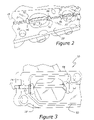
- FIG. 3 is a perspective view showing details of a control shaft mounting according to an aspect of the present disclosure.
- FIG. 4 is a perspective view showing details of a prior art control shaft mounting which uses a spacer to accommodate the control shaft.
- an intake manifold system, 10 has a number of inlet runners, 14 , extending from a throttle valve, 38 , and plenum, 40 , to a mounting flange, 18 .
- Runners 14 are preferably one-piece with mounting flange 18 .
- Mounting flange 18 has a cylinder head engaging surface, 20 , which is generally planar, and which has a control shaft passage, 26 , formed therein. Passage 26 may either be produced by machining of mounting flange 18 , or it may be cored and formed during a casting or molding operation. Because control shaft passage 26 is configured as an open channel for most of its length, passage 26 is readily created by either drilling and milling or slotting mounting flange 18 .
- control shaft passage 26 houses a control shaft, 22 , having a number of charge air control elements contained thereupon. These elements may include charge motion control valves, shown at 30 in FIG. 2 , runner control valves shown at 34 in FIG. 1 , or other types of elements which change the flow characteristics through the manifold's runners. Alternatively, more than one type of device, e.g., charge motion control valves and runner control valves, may be employed in a single intake manifold system.
- Charge motion control valves 30 are illustrated as having one-quarter of the valve plate removed, so as to cause air flowing through a manifold runner to be re-directed.
- runners 14 are shown as being bifurcated, in FIG. 1 , FIGS. 2 and 3 show a non-bifurcated runner system, the point being that the present system is useful with both types of charge air control elements.
- the present system may be employed with intake manifolds rendered in various metals, nonmetals, and composites, either by traditional casting methods, or as shell welded assemblies, or yet other types of construction.
- FIG. 1 also shows a control motor, 42 , and controller 46 , which rotationally positions control shaft 22 and charge air control elements whether they be CMCV 30 or runner control valves 34 , or both.
- FIG. 2 illustrates control shaft 22 as being journaled within mounting flange 18 by a number of bearing sections configured as bushings, 52 , which fit within bushing apertures 56 .
- bushings 52 extends within mounting flange 18 from control shaft passage 26 to cylinder head engaging surface 20 .
- bushings 52 are molded from an elastomeric compound which is sized to fit in a compressed state within bushing apertures 56 , and is in effect clamped and retained within bushing apertures 56 by clamping force applied by a cylinder head (not shown) which abuts each of bushings 52 when mounting flange 18 has been attached to the cylinder head of an engine.
- FIG. 3 shows more detail of bushing apertures 56 and bushings 52 , as well as shaft 22 .
- the present intake manifold system preferably further includes a sealing composition, 50 , applied as a continuous loop to an outer periphery of mounting flange 18 so as to prevent the leakage of air past mounting flange 18 and into an engine to which the present intake manifold system is attached.
- sealing composition 50 need not extend between the various runners, limited air exchange will be permitted between adjacent ones of the inlet runners. Testing has shown that this air exchange will not appreciably degrade induction system tuning, provided bushings 52 impose a reasonable restriction upon pressure pulses seeking to communicate between runners 14 parallel to control shaft 22 .
Landscapes
- Engineering & Computer Science (AREA)
- Chemical & Material Sciences (AREA)
- Combustion & Propulsion (AREA)
- Mechanical Engineering (AREA)
- General Engineering & Computer Science (AREA)
- Control Of Throttle Valves Provided In The Intake System Or In The Exhaust System (AREA)
Abstract
Description
Claims (16)
Priority Applications (3)
| Application Number | Priority Date | Filing Date | Title |
|---|---|---|---|
| US12/470,533 US8056534B2 (en) | 2009-05-22 | 2009-05-22 | Intake manifold system for internal combustion engine |
| DE102010019427A DE102010019427A1 (en) | 2009-05-22 | 2010-05-05 | Intake manifold system for internal combustion engine |
| CN2010202048375U CN201858060U (en) | 2009-05-22 | 2010-05-21 | Intake manifold system for internal combustion engine |
Applications Claiming Priority (1)
| Application Number | Priority Date | Filing Date | Title |
|---|---|---|---|
| US12/470,533 US8056534B2 (en) | 2009-05-22 | 2009-05-22 | Intake manifold system for internal combustion engine |
Publications (2)
| Publication Number | Publication Date |
|---|---|
| US20100294227A1 US20100294227A1 (en) | 2010-11-25 |
| US8056534B2 true US8056534B2 (en) | 2011-11-15 |
Family
ID=43028744
Family Applications (1)
| Application Number | Title | Priority Date | Filing Date |
|---|---|---|---|
| US12/470,533 Expired - Fee Related US8056534B2 (en) | 2009-05-22 | 2009-05-22 | Intake manifold system for internal combustion engine |
Country Status (3)
| Country | Link |
|---|---|
| US (1) | US8056534B2 (en) |
| CN (1) | CN201858060U (en) |
| DE (1) | DE102010019427A1 (en) |
Cited By (6)
| Publication number | Priority date | Publication date | Assignee | Title |
|---|---|---|---|---|
| US20120312275A1 (en) * | 2009-11-23 | 2012-12-13 | Marc Eisele | Flat device and intake system |
| US20130037000A1 (en) * | 2011-08-12 | 2013-02-14 | Roechling Automotive Ag & Co. Kg | Valve device with at least two separately produced valves assembled together for joint movement |
| USD677700S1 (en) * | 2012-09-24 | 2013-03-12 | Group A Autosports, Inc. | Intake manifold |
| DE102016123676A1 (en) | 2015-12-11 | 2017-06-14 | Ford Global Technologies, Llc | Charge movement flap seal and assembly method |
| US10012187B1 (en) | 2017-01-05 | 2018-07-03 | Ford Global Technologies, Llc | Charge motion control valve |
| US11536230B1 (en) | 2021-10-26 | 2022-12-27 | Ford Global Technologies, Llc | Charge-air cooler and water distribution device to evenly proved water to engine cylinders |
Families Citing this family (17)
| Publication number | Priority date | Publication date | Assignee | Title |
|---|---|---|---|---|
| CN102562380A (en) * | 2012-02-29 | 2012-07-11 | 长城汽车股份有限公司 | Air intake device of multi-cylinder pressurization engine |
| USD673977S1 (en) * | 2012-03-15 | 2013-01-08 | Group-A Autosports, Inc. | Intake manifold |
| USD674408S1 (en) * | 2012-03-15 | 2013-01-15 | Group-A Autosports, Inc. | Intake manifold |
| USD673978S1 (en) * | 2012-03-15 | 2013-01-08 | Group-A Autosports, Inc. | Intake manifold |
| JP5867322B2 (en) * | 2012-07-04 | 2016-02-24 | アイシン精機株式会社 | Airflow control device |
| JP6096055B2 (en) * | 2013-05-29 | 2017-03-15 | 富士重工業株式会社 | Mounting structure of intake flow control valve device |
| KR101465348B1 (en) * | 2013-06-27 | 2014-11-26 | 주식회사 현대케피코 | Actuator for intake manifold |
| JP6205968B2 (en) * | 2013-08-19 | 2017-10-04 | アイシン精機株式会社 | Intake device |
| DE102013017166B4 (en) * | 2013-10-16 | 2020-07-09 | Mann+Hummel Gmbh | Detachable connecting device for connecting at least two functional components and functional component |
| JP6281295B2 (en) * | 2014-01-27 | 2018-02-21 | アイシン精機株式会社 | Airflow control valve structure and intake device |
| JP6176144B2 (en) * | 2014-02-21 | 2017-08-09 | トヨタ紡織株式会社 | Intake manifold for internal combustion engines |
| USD788173S1 (en) * | 2015-09-22 | 2017-05-30 | Group-A Autosports, Inc. | Intake manifold |
| USD892171S1 (en) * | 2019-05-19 | 2020-08-04 | Deepmotor, Inc. | Intake manifold |
| USD899460S1 (en) * | 2019-05-19 | 2020-10-20 | Deepmotor, Inc. | Intake manifold |
| USD892172S1 (en) * | 2019-05-19 | 2020-08-04 | Deepmotor, Inc. | Intake manifold |
| USD899459S1 (en) * | 2019-05-19 | 2020-10-20 | Deepmotor, Inc. | Intake manifold |
| USD962291S1 (en) | 2021-08-06 | 2022-08-30 | Deepmotor Inc | Intake manifold |
Citations (28)
| Publication number | Priority date | Publication date | Assignee | Title |
|---|---|---|---|---|
| US4180041A (en) | 1976-03-05 | 1979-12-25 | Nissan Motor Company, Limited | Internal combustion engine with intake arrangement to produce swirl in combustion chamber |
| US4819953A (en) | 1986-11-15 | 1989-04-11 | Karl Joh Gummiwarenfabrik Gmbh | Cylinder head cover with gasket and method of making the gasket |
| US5005535A (en) * | 1989-02-27 | 1991-04-09 | Outboard Marine Corporation | Internal Combustion engine with recessed intake manifold |
| US5107804A (en) | 1989-10-16 | 1992-04-28 | Borg-Warner Automotive Transmission & Engine Components Corporation | Variable camshaft timing for internal combustion engine |
| US5145190A (en) | 1991-03-27 | 1992-09-08 | Freudenberg-Nok | Gasket assembly |
| US5267543A (en) | 1992-12-21 | 1993-12-07 | Ford Motor Company | Dual induction system for internal combustion engine |
| US5280769A (en) | 1993-05-04 | 1994-01-25 | General Motors Corporation | Pressure relief means for induction system |
| US5657725A (en) | 1994-09-15 | 1997-08-19 | Borg-Warner Automotive, Inc. | VCT system utilizing engine oil pressure for actuation |
| US5704333A (en) | 1995-10-19 | 1998-01-06 | Toyota Jidosha Kabushiki Kaisha | Fuel injection system for a lean burn engine |
| US5875758A (en) * | 1995-04-06 | 1999-03-02 | E. I. Du Pont De Nemours And Company | Resin air intake system provided with intake control valve |
| US5957464A (en) | 1997-07-11 | 1999-09-28 | Interwave Communications | Split dove-tail gasket channel for round gasket material |
| US6055806A (en) | 1998-05-08 | 2000-05-02 | Caterpillar Inc. | Exhaust manifold seals to eliminate oil slobber |
| US6311986B1 (en) | 1999-02-15 | 2001-11-06 | Hudson Products Corporation | Seal joint between internals and pressure vessel inlet for separator arrangement |
| JP2002106428A (en) | 2000-09-29 | 2002-04-10 | Suzuki Motor Corp | Engine intake manifold |
| US6604506B2 (en) * | 2000-09-28 | 2003-08-12 | Mazda Motor Corporation | Intake manifold of engine |
| US6662772B1 (en) | 1999-11-12 | 2003-12-16 | Siemens Canada Limited | Integrated swirl control valve |
| US20040134192A1 (en) | 2002-06-28 | 2004-07-15 | Tsutomu Umehara | Apparatus and method for controlling EGR in an engine |
| US6763802B1 (en) | 2002-11-25 | 2004-07-20 | Hayes Lemmerz International, Inc. | Intake manifold valve system |
| US20050179215A1 (en) | 2004-02-18 | 2005-08-18 | Eagle Engineering Aerospace Co., Ltd. | Seal device |
| US7096849B1 (en) | 2005-07-12 | 2006-08-29 | Steeda Autosports, Inc. | Charge motion control plate kit |
| US20070017468A1 (en) | 2005-07-20 | 2007-01-25 | Siemens Vdo Automotive Inc. | Intake manifold cross talk sealing |
| US20070044754A1 (en) * | 2005-08-24 | 2007-03-01 | Peffley Thomas R | Variable center pivot tumble control valve geometry for an intake manifold |
| US7293546B1 (en) * | 2006-05-08 | 2007-11-13 | Delphi Technologies, Inc. | Charge motion control device using a single common drive shaft |
| US20080035107A1 (en) * | 2006-08-11 | 2008-02-14 | Denso Corporation | Integrated valve device |
| US7337758B2 (en) | 2004-03-25 | 2008-03-04 | Sturdy Corporation | Charge motion control valve actuator |
| US20080271697A1 (en) | 2007-05-02 | 2008-11-06 | Mann & Hummel Gmbh | Lower Intake Manifold with Charge Motion Control Valve |
| US7552710B2 (en) * | 2006-10-05 | 2009-06-30 | Magneti Marelli Powertrain S.P.A. | Variable geometry intake manifold for an internal combustion engine |
| US7624715B2 (en) * | 2007-10-02 | 2009-12-01 | Dayco Products, Llc | System and method for controlling turbulence in a combustion engine |
-
2009
- 2009-05-22 US US12/470,533 patent/US8056534B2/en not_active Expired - Fee Related
-
2010
- 2010-05-05 DE DE102010019427A patent/DE102010019427A1/en not_active Withdrawn
- 2010-05-21 CN CN2010202048375U patent/CN201858060U/en not_active Expired - Lifetime
Patent Citations (28)
| Publication number | Priority date | Publication date | Assignee | Title |
|---|---|---|---|---|
| US4180041A (en) | 1976-03-05 | 1979-12-25 | Nissan Motor Company, Limited | Internal combustion engine with intake arrangement to produce swirl in combustion chamber |
| US4819953A (en) | 1986-11-15 | 1989-04-11 | Karl Joh Gummiwarenfabrik Gmbh | Cylinder head cover with gasket and method of making the gasket |
| US5005535A (en) * | 1989-02-27 | 1991-04-09 | Outboard Marine Corporation | Internal Combustion engine with recessed intake manifold |
| US5107804A (en) | 1989-10-16 | 1992-04-28 | Borg-Warner Automotive Transmission & Engine Components Corporation | Variable camshaft timing for internal combustion engine |
| US5145190A (en) | 1991-03-27 | 1992-09-08 | Freudenberg-Nok | Gasket assembly |
| US5267543A (en) | 1992-12-21 | 1993-12-07 | Ford Motor Company | Dual induction system for internal combustion engine |
| US5280769A (en) | 1993-05-04 | 1994-01-25 | General Motors Corporation | Pressure relief means for induction system |
| US5657725A (en) | 1994-09-15 | 1997-08-19 | Borg-Warner Automotive, Inc. | VCT system utilizing engine oil pressure for actuation |
| US5875758A (en) * | 1995-04-06 | 1999-03-02 | E. I. Du Pont De Nemours And Company | Resin air intake system provided with intake control valve |
| US5704333A (en) | 1995-10-19 | 1998-01-06 | Toyota Jidosha Kabushiki Kaisha | Fuel injection system for a lean burn engine |
| US5957464A (en) | 1997-07-11 | 1999-09-28 | Interwave Communications | Split dove-tail gasket channel for round gasket material |
| US6055806A (en) | 1998-05-08 | 2000-05-02 | Caterpillar Inc. | Exhaust manifold seals to eliminate oil slobber |
| US6311986B1 (en) | 1999-02-15 | 2001-11-06 | Hudson Products Corporation | Seal joint between internals and pressure vessel inlet for separator arrangement |
| US6662772B1 (en) | 1999-11-12 | 2003-12-16 | Siemens Canada Limited | Integrated swirl control valve |
| US6604506B2 (en) * | 2000-09-28 | 2003-08-12 | Mazda Motor Corporation | Intake manifold of engine |
| JP2002106428A (en) | 2000-09-29 | 2002-04-10 | Suzuki Motor Corp | Engine intake manifold |
| US20040134192A1 (en) | 2002-06-28 | 2004-07-15 | Tsutomu Umehara | Apparatus and method for controlling EGR in an engine |
| US6763802B1 (en) | 2002-11-25 | 2004-07-20 | Hayes Lemmerz International, Inc. | Intake manifold valve system |
| US20050179215A1 (en) | 2004-02-18 | 2005-08-18 | Eagle Engineering Aerospace Co., Ltd. | Seal device |
| US7337758B2 (en) | 2004-03-25 | 2008-03-04 | Sturdy Corporation | Charge motion control valve actuator |
| US7096849B1 (en) | 2005-07-12 | 2006-08-29 | Steeda Autosports, Inc. | Charge motion control plate kit |
| US20070017468A1 (en) | 2005-07-20 | 2007-01-25 | Siemens Vdo Automotive Inc. | Intake manifold cross talk sealing |
| US20070044754A1 (en) * | 2005-08-24 | 2007-03-01 | Peffley Thomas R | Variable center pivot tumble control valve geometry for an intake manifold |
| US7293546B1 (en) * | 2006-05-08 | 2007-11-13 | Delphi Technologies, Inc. | Charge motion control device using a single common drive shaft |
| US20080035107A1 (en) * | 2006-08-11 | 2008-02-14 | Denso Corporation | Integrated valve device |
| US7552710B2 (en) * | 2006-10-05 | 2009-06-30 | Magneti Marelli Powertrain S.P.A. | Variable geometry intake manifold for an internal combustion engine |
| US20080271697A1 (en) | 2007-05-02 | 2008-11-06 | Mann & Hummel Gmbh | Lower Intake Manifold with Charge Motion Control Valve |
| US7624715B2 (en) * | 2007-10-02 | 2009-12-01 | Dayco Products, Llc | System and method for controlling turbulence in a combustion engine |
Cited By (10)
| Publication number | Priority date | Publication date | Assignee | Title |
|---|---|---|---|---|
| US20120312275A1 (en) * | 2009-11-23 | 2012-12-13 | Marc Eisele | Flat device and intake system |
| US8752525B2 (en) * | 2009-11-23 | 2014-06-17 | Mahle International Gmbh | Flap device and intake system |
| US20130037000A1 (en) * | 2011-08-12 | 2013-02-14 | Roechling Automotive Ag & Co. Kg | Valve device with at least two separately produced valves assembled together for joint movement |
| US8739761B2 (en) * | 2011-08-12 | 2014-06-03 | Rochling Automotive Ag & Co. Kg | Valve device with at least two separately produced valves assembled together for joint movement |
| USD677700S1 (en) * | 2012-09-24 | 2013-03-12 | Group A Autosports, Inc. | Intake manifold |
| DE102016123676A1 (en) | 2015-12-11 | 2017-06-14 | Ford Global Technologies, Llc | Charge movement flap seal and assembly method |
| US10087899B2 (en) | 2015-12-11 | 2018-10-02 | Ford Global Technologies, Llc | Charge motion control valve seal and method of assembly |
| DE102016123676B4 (en) | 2015-12-11 | 2025-01-23 | Ford Global Technologies, Llc | Cargo movement flap seal and assembly method |
| US10012187B1 (en) | 2017-01-05 | 2018-07-03 | Ford Global Technologies, Llc | Charge motion control valve |
| US11536230B1 (en) | 2021-10-26 | 2022-12-27 | Ford Global Technologies, Llc | Charge-air cooler and water distribution device to evenly proved water to engine cylinders |
Also Published As
| Publication number | Publication date |
|---|---|
| US20100294227A1 (en) | 2010-11-25 |
| CN201858060U (en) | 2011-06-08 |
| DE102010019427A1 (en) | 2010-12-02 |
Similar Documents
| Publication | Publication Date | Title |
|---|---|---|
| US8056534B2 (en) | Intake manifold system for internal combustion engine | |
| US8122864B2 (en) | Intake manifold for multicylinder internal combustion engine | |
| US7802555B2 (en) | Intake control device for an engine | |
| US5979401A (en) | Internal combustion engine having induction system with aerodynamic charge motion control valve | |
| SE521262C2 (en) | Combustion engine with exhaust gas recirculation | |
| WO2001036796A1 (en) | Integrated swirl control valve | |
| US8069664B2 (en) | Integrated inlet and bypass throttle for positive-displacement supercharged engines | |
| EP2138691B1 (en) | Air intake apparatus for internal combustion engine | |
| US9032931B2 (en) | Exhaust gas recirculation (EGR) apparatus | |
| US20020117139A1 (en) | Air intake device for an internal combustion engine and methods for its operation | |
| US7096849B1 (en) | Charge motion control plate kit | |
| US20080184960A1 (en) | Throttle body with integrated reversion restriction | |
| US7178496B2 (en) | Intake manifold for an engine and method of controlling intake air flow | |
| JP2013540942A (en) | Internal combustion engine and method for manufacturing the internal combustion engine | |
| JP3372378B2 (en) | Structure of spark ignition type internal combustion engine equipped with fuel injection valve | |
| US8100108B2 (en) | Hydraulically operated charge air system for internal combustion engine | |
| JPWO2018069975A1 (en) | Intake passage structure of a turbocharged engine | |
| KR19990029143A (en) | Intake apparatus of internal combustion engine | |
| JPH0257209B2 (en) | ||
| JPH0437229Y2 (en) | ||
| JPS626252Y2 (en) | ||
| JP6157147B2 (en) | Blowby gas recirculation system | |
| JP3209578B2 (en) | Engine intake system | |
| JP2000227057A (en) | Engine intake system | |
| US20040159308A1 (en) | Integrated air and fuel carrier module |
Legal Events
| Date | Code | Title | Description |
|---|---|---|---|
| AS | Assignment |
Owner name: FORD GLOBAL TECHNOLOGIES, LLC, MICHIGAN Free format text: ASSIGNMENT OF ASSIGNORS INTEREST;ASSIGNORS:MAGNAN, MICHAEL BRUNO;RANDALL, KATHERINE JANE;NEWMAN, CHRISTOPHER WILLIAM;SIGNING DATES FROM 20090520 TO 20090521;REEL/FRAME:022724/0078 |
|
| FEPP | Fee payment procedure |
Free format text: PAYOR NUMBER ASSIGNED (ORIGINAL EVENT CODE: ASPN); ENTITY STATUS OF PATENT OWNER: LARGE ENTITY |
|
| ZAAA | Notice of allowance and fees due |
Free format text: ORIGINAL CODE: NOA |
|
| ZAAB | Notice of allowance mailed |
Free format text: ORIGINAL CODE: MN/=. |
|
| STCF | Information on status: patent grant |
Free format text: PATENTED CASE |
|
| FPAY | Fee payment |
Year of fee payment: 4 |
|
| MAFP | Maintenance fee payment |
Free format text: PAYMENT OF MAINTENANCE FEE, 8TH YEAR, LARGE ENTITY (ORIGINAL EVENT CODE: M1552); ENTITY STATUS OF PATENT OWNER: LARGE ENTITY Year of fee payment: 8 |
|
| FEPP | Fee payment procedure |
Free format text: MAINTENANCE FEE REMINDER MAILED (ORIGINAL EVENT CODE: REM.); ENTITY STATUS OF PATENT OWNER: LARGE ENTITY |
|
| LAPS | Lapse for failure to pay maintenance fees |
Free format text: PATENT EXPIRED FOR FAILURE TO PAY MAINTENANCE FEES (ORIGINAL EVENT CODE: EXP.); ENTITY STATUS OF PATENT OWNER: LARGE ENTITY |
|
| STCH | Information on status: patent discontinuation |
Free format text: PATENT EXPIRED DUE TO NONPAYMENT OF MAINTENANCE FEES UNDER 37 CFR 1.362 |
|
| FP | Lapsed due to failure to pay maintenance fee |
Effective date: 20231115 |