US8055092B2 - Image processing apparatus and image processing method - Google Patents
Image processing apparatus and image processing method Download PDFInfo
- Publication number
- US8055092B2 US8055092B2 US12/154,640 US15464008A US8055092B2 US 8055092 B2 US8055092 B2 US 8055092B2 US 15464008 A US15464008 A US 15464008A US 8055092 B2 US8055092 B2 US 8055092B2
- Authority
- US
- United States
- Prior art keywords
- brightness
- pixel
- weight
- interest
- level
- Prior art date
- Legal status (The legal status is an assumption and is not a legal conclusion. Google has not performed a legal analysis and makes no representation as to the accuracy of the status listed.)
- Active, expires
Links
- 238000003672 processing method Methods 0.000 title claims description 19
- 238000010586 diagram Methods 0.000 description 8
- 206010033307 Overweight Diseases 0.000 description 3
- 206010048828 underweight Diseases 0.000 description 3
- 230000008901 benefit Effects 0.000 description 2
- 238000000034 method Methods 0.000 description 2
Images


Classifications
-
- G06T5/94—
-
- H—ELECTRICITY
- H04—ELECTRIC COMMUNICATION TECHNIQUE
- H04N—PICTORIAL COMMUNICATION, e.g. TELEVISION
- H04N5/00—Details of television systems
- H04N5/14—Picture signal circuitry for video frequency region
- H04N5/20—Circuitry for controlling amplitude response
- H04N5/205—Circuitry for controlling amplitude response for correcting amplitude versus frequency characteristic
- H04N5/208—Circuitry for controlling amplitude response for correcting amplitude versus frequency characteristic for compensating for attenuation of high frequency components, e.g. crispening, aperture distortion correction
-
- G—PHYSICS
- G06—COMPUTING; CALCULATING OR COUNTING
- G06T—IMAGE DATA PROCESSING OR GENERATION, IN GENERAL
- G06T5/00—Image enhancement or restoration
- G06T5/20—Image enhancement or restoration by the use of local operators
-
- H—ELECTRICITY
- H04—ELECTRIC COMMUNICATION TECHNIQUE
- H04N—PICTORIAL COMMUNICATION, e.g. TELEVISION
- H04N9/00—Details of colour television systems
- H04N9/77—Circuits for processing the brightness signal and the chrominance signal relative to each other, e.g. adjusting the phase of the brightness signal relative to the colour signal, correcting differential gain or differential phase
-
- G—PHYSICS
- G06—COMPUTING; CALCULATING OR COUNTING
- G06T—IMAGE DATA PROCESSING OR GENERATION, IN GENERAL
- G06T2207/00—Indexing scheme for image analysis or image enhancement
- G06T2207/20—Special algorithmic details
- G06T2207/20024—Filtering details
- G06T2207/20028—Bilateral filtering
Definitions
- the present invention relates to an image processing apparatus and an image processing method, and more particularly, to an image processing apparatus and an image processing method by which noise on a plane part of an image is reduced and at the same time the contour of an edge part of the image is emphasized.
- the boundary of an object included in an image output from a general image processing apparatus such as a digital camera built into a mobile phone may be blurred.
- An image contour denotes a boundary in which the location, shape, size, etc. of an object is changed. Such an image contour has a lot of information about the image and exists at a point where the brightness of the image changes from a low value to a high value or vice versa.
- the image contour has been emphasized using a sharpening filter that is suitable for image signals.
- a sharpening filter causes noise generated on a plane part of an image to be reinforced.
- the present invention provides an image processing apparatus and an image processing method by which noise generated on a plane part of an image is minimized and the contour of the image is appropriately emphasized, consequently improving the definition of images.
- the present invention also provides an image processing apparatus and an image processing method by which detailed information included in an image is inspected and the image is then processed considering the detailed information, consequently efficiently improving the quality of output images.
- an image processing apparatus comprising: a brightness change level classifying unit comparing a brightness change average value representing brightness changes from a pixel of interest to neighboring pixels around the pixel of interest with an upper threshold value and a lower threshold value and classifying a brightness change level of the pixel of interest into three types of levels according to a result of the comparison, wherein the upper threshold value and the lower threshold value are predetermined based on a brightness of the pixel of interest; a dynamic weight calculating unit calculating different dynamic weights according to the brightness change level of the pixel of interest; and a brightness correcting unit correcting the brightness of the pixel of interest, based on the dynamic weights.
- the brightness change level classifying unit may comprise: a brightness variation calculating unit for calculating 8 brightness variations of 8 3 ⁇ 3 pixel areas surrounding, in 8 directions, a central 3 ⁇ 3 pixel area that includes a pixel of interest as a center pixel, wherein all the 3 ⁇ 3 pixel areas are within a 5 ⁇ 5 pixel area; and a comparing/classifying unit for comparing a brightness change average value corresponding to a mean of the 8 brightness variations with the lower threshold value and the upper threshold value, and classifying a brightness change level of the pixel of interest into three types of levels.
- Predetermined weights may be applied to center pixels of the 8 3 ⁇ 3 pixel areas and the central 3 ⁇ 3 pixel area.
- the comparing/classifying unit may classify the brightness change level of the pixel of interest into a first level.
- the comparing/classifying unit may classify the brightness change level of the pixel of interest into a second level.
- the comparing/classifying unit may classify the brightness change level of the pixel of interest into a third level.
- the upper and lower threshold values may be obtained by multiplying two different proportionality constants by an average brightness of the central 3 ⁇ 3 pixel area.
- the dynamic weight calculating unit may comprise: a first weight calculating unit calculating a first weight, based on the brightness change level of the pixel of interest; and a second weight adding unit adding a second weight to the first weight, based on the brightness of the pixel of interest.
- the first weight calculating unit may calculate a low-level first weight.
- the first weight calculating unit may calculate a high-level first weight.
- the first weight calculating unit may calculate an intermediate-level first weight that gradually increases from the low-level first weight to the high-level first weight.
- the intermediate-level first weight may linearly increase from the low-level first weight to the high-level first weight.
- the second weight adding unit may add a second weight having a value of 1 to the first weight.
- the second weight adding unit may add a second weight which is proportional to the brightness of the pixel of interest and has a value of 1 or less, to the first weight.
- the second weight adding unit may add a second weight which is inversely proportional to the brightness of the pixel of interest and has a value of 1 or less, to the first weight.
- the brightness correcting unit may comprise: a brightness difference calculating unit for calculating a brightness difference by subtracting an average brightness from the brightness of the pixel of interest, wherein the average brightness is obtained by applying, to the 5 ⁇ 5 pixel area, a mask having weights increasing toward the center of the 5 ⁇ 5 pixel area; and a corrected brightness calculating unit for calculating a corrected brightness adding the average brightness to a value obtained by multiplying the brightness difference from the brightness difference calculating unit and the dynamic weight from the dynamic weight calculating unit.
- an image processing method comprising: a brightness change level classifying operation of comparing a brightness change average value representing brightness changes from a pixel of interest to neighboring pixels around the pixel of interest with an upper threshold value and a lower threshold value and classifying the brightness change level of the pixel of interest into three types of levels according to a result of the comparison, wherein the upper threshold value and the lower threshold value are predetermined based on a brightness of the pixel of interest; a dynamic weight calculating operation of calculating different dynamic weights according to the brightness change level of the pixel of interest; and a brightness correcting operation of correcting the brightness of the pixel of interest, based on the dynamic weights.
- the brightness change level classifying operation may comprise: a brightness variation calculating sub-operation of calculating 8 brightness variations of 8 3 ⁇ 3 pixel areas surrounding, in 8 directions, a central 3 ⁇ 3 pixel area that includes a pixel of interest as a center pixel, wherein all the 3 ⁇ 3 pixel areas are within a 5 ⁇ 5 pixel area; and a comparing/classifying operation that include (1) comparing a brightness change average value corresponding to a mean of the 8 brightness variations with the lower threshold value and the upper threshold value, and (2) classifying a brightness change level of the pixel of interest into three types of levels.
- Predetermined weights may be applied to center pixels of the 8 3 ⁇ 3 pixel areas and the central 3 ⁇ 3 pixel area.
- the brightness change level of the pixel of interest when the brightness change average value is less than or equal to the lower threshold value, the brightness change level of the pixel of interest may be classified into a first level; when the brightness change average value is more than the lower threshold value and less than the upper threshold value, the brightness change level of the pixel of interest may be classified into a second level; and when the brightness change average value is equal to or more than the upper threshold value, the brightness change level of the pixel of interest may be classified into a third level.
- the dynamic weight calculating operation may comprise: a first weight calculating sub-operation of calculating a first weight, based on the brightness change level of the pixel of interest; and a second weight adding sub-operation of adding a second weight to the first weight, based on the brightness of the pixel of interest.
- a low-level first weight when the brightness change level of the pixel of interest is classified into the first level, a low-level first weight may be calculated; when the brightness change level of the pixel of interest is classified into the third level, a high-level first weight may be calculated; and when the brightness change level of the pixel of interest is classified into the second level, an intermediate-level first weight that gradually increases from the low-level first weight to the high-level first weight may be calculated.
- the intermediate-level first weight may linearly increase from the low-level first weight to the high-level first weight.
- a second weight having a value of 1 may be added to the first weight; when the brightness of the pixel of interest is less than or equal to 20% of the maximum gray scale, a second weight which is proportional to the brightness of the pixel of interest and has a value of 1 or less, may be added to the first weight; and when the brightness of the pixel of interest is equal to or more than 80% of the maximum gray scale, a second weight which is inversely proportional to the brightness of the pixel of interest and has a value of 1 or less, may be added to the first weight.
- the brightness correcting operation may comprise: a brightness difference calculating sub-operation of calculating a brightness difference by subtracting an average brightness from the brightness of the pixel of interest, wherein the average brightness is obtained by applying, to the 5 ⁇ 5 pixel area, a mask having weights increasing toward the center of the 5 ⁇ 5 pixel area; and a corrected brightness calculating sub-operation of calculating a corrected brightness by adding the average brightness to a value obtained by multiplying the brightness difference from the brightness difference calculating sub-operation and the dynamic weight from the dynamic weight calculating operation.
- FIG. 1 is a block diagram of an image processing apparatus according to an embodiment of the present invention.
- FIG. 2 is a block diagram of a brightness change level classifying unit illustrated in FIG. 1 ;
- FIGS. 3 through 6 illustrate a method of calculating brightness variations of a 5 ⁇ 5 pixel area including a pixel of interest in 8 directions;
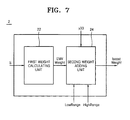
- FIG. 7 is a block diagram of a dynamic weight calculating unit illustrated in FIG. 1 ;
- FIG. 8 is a graph for illustrating an operation of a first weight calculating unit illustrated in FIG. 7 ;
- FIG. 9 is a graph for illustrating an operation of a second weight adding unit illustrated in FIG. 7 ;
- FIG. 10 is a block diagram of a brightness correcting unit illustrated in FIG. 1 ;
- FIGS. 11 through 13 illustrate results of an image processing experiment performed by the image processing apparatus illustrated in FIG. 1 .
- FIG. 1 is a block diagram of an image processing apparatus according to an embodiment of the present invention.
- the image processing apparatus according to the current embodiment includes a brightness change level classifying unit 1 , a dynamic weight calculating unit 2 , and a brightness correcting unit 3 .
- the brightness change level classifying unit 1 compares a brightness change average value representing brightness changes from a pixel of interest to neighboring pixels around the pixel of interest with an upper threshold value and a lower threshold value that are predetermined based on the brightness of the pixel of interest and classifies the brightness change level of the pixel of interest into three types of levels according to the result of the comparison.
- the brightness change level classifying unit 1 may be configured as illustrated in FIG. 2 .
- FIG. 2 is a block diagram of the brightness change level classifying unit 1 of FIG. 1 .
- the brightness change level classifying unit 1 includes a brightness variation calculating unit 12 , a threshold value calculating unit 14 , and a comparing/classifying unit 16 .
- the brightness variation calculating unit 12 calculates 8 brightness variations H 1 , H 2 , V 1 , V 2 , S 1 , S 2 , B 1 , and B 2 of 8 3 ⁇ 3 pixel areas, whose centers are respectively pixels y 22 , y 23 , y 24 , y 32 , y 34 , y 42 , y 43 , and y 44 , existing in 8 directions from a central 3 ⁇ 3 pixel area PVV including a pixel of interest y 33 within a 5 ⁇ 5 pixel area PA.
- FIGS. 3 through 6 illustrate a method of calculating brightness variations of the 8 3 ⁇ 3 pixel areas existing in 8 directions within the 5 ⁇ 5 pixel area PA including the pixel of interest y 33 .
- the brightness variation H 1 of a left 3 ⁇ 3 pixel area PUU 1 existing on a left side of the central 3 ⁇ 3 pixel area PVV including the pixel of interest y 33 and the brightness variation H 2 of a right 3 ⁇ 3 pixel area PWW 1 existing on a right side of the central 3 ⁇ 3 pixel area PVV are calculated using Equations 1 and 2:
- H ⁇ ⁇ 1 ⁇ VV - UU ⁇ ⁇ 1 ⁇ VV ( 1 )
- H 1 indicates the brightness variation of the left 3 ⁇ 3 pixel area PUU 1 on the left side of the central 3 ⁇ 3 pixel area PVV including the pixel of interest y 33
- VV indicates an average brightness of the central 3 ⁇ 3 pixel area PVV including the pixel of interest y 33
- UU 1 indicates an average brightness of the left 3 ⁇ 3 pixel area PUU 1 .
- An average brightness of each 3 ⁇ 3 pixel area is calculated after a predetermined weight is applied to the center pixel of each 3 ⁇ 3 pixel area. For example, upon calculation of VV as illustrated in FIG.
- a weight applied to the center pixel y 33 of the central 3 ⁇ 3 pixel area PVV may be 8 times as large as those applied to neighboring pixels y 22 , y 23 , y 24 , y 32 , y 34 , y 42 , y 43 , and y 44 around the center pixel y 33 .
- the value of the weight applied to the center pixel y 33 is not limited to the value which is 8 times as large as the values applied to the neighboring pixels.
- the weights which are applied to the center pixels of the 3 ⁇ 3 pixel areas during calculations of the average brightness values of the 3 ⁇ 3 pixel areas may be equal to the value of the weight applied to the center pixel y 33 of the central 3 ⁇ 3 pixel area PVV and used in Equations 2 through 8.
- Equation 2 Equation 2
- H ⁇ ⁇ 2 ⁇ VV - WW ⁇ ⁇ 1 ⁇ VV ( 2 ) wherein H 2 indicates the brightness variation of the right 3 ⁇ 3 pixel area PWW 1 on the right side of the central 3 ⁇ 3 pixel area PVV, VV indicates the average brightness of the central 3 ⁇ 3 pixel area PVV, and WW 1 indicates an average brightness of the right 3 ⁇ 3 pixel area PWW 1 .
- the brightness variation V 1 of an upper 3 ⁇ 3 pixel area PUU 2 existing on an upper side of the central 3 ⁇ 3 pixel area PVV and the brightness variation V 2 of a lower 3 ⁇ 3 pixel area PWW 2 existing on a lower side of the central 3 ⁇ 3 pixel area PVV are calculated using Equations 3 and 4:
- V ⁇ ⁇ 1 ⁇ VV - UU ⁇ ⁇ 2 ⁇ VV ( 3 )
- V ⁇ ⁇ 2 ⁇ VV - WW ⁇ ⁇ 2 ⁇ VV ( 4 )
- V 1 indicates the brightness variation of the upper 3 ⁇ 3 pixel area PUU 2 on the upper side of the central 3 ⁇ 3 pixel area PVV
- VV indicates the average brightness of the 3 ⁇ 3 pixel area PVV
- UU 2 indicates an average brightness of the upper 3 ⁇ 3 pixel area PUU 2
- V 2 indicates the brightness variation of the lower 3 ⁇ 3 pixel area PWW 2 on the lower side of the central 3 ⁇ 3 pixel area PVV
- WW 2 indicates an average brightness of the lower 3 ⁇ 3 pixel area PWW 2 .
- the brightness variation S 1 of a right upper 3 ⁇ 3 pixel area PUU 3 existing on a right upper side of the central 3 ⁇ 3 pixel area PVV including and the brightness variation S 2 of a left lower 3 ⁇ 3 pixel area PWW 3 existing on a left lower side of the central 3 ⁇ 3 pixel area PVV are calculated using Equations 5 and 6:
- S ⁇ ⁇ 1 ⁇ VV - UU ⁇ ⁇ 3 ⁇ VV ( 5 )
- S ⁇ ⁇ 2 ⁇ VV - WW ⁇ ⁇ 3 ⁇ VV ( 6 )
- S 1 indicates the brightness variation of the right upper 3 ⁇ 3 pixel area PUU 3 on the right upper side of the central 3 ⁇ 3 pixel area PVV
- VV indicates the average brightness of the central 3 ⁇ 3 pixel area PVV
- UU 3 indicates an average brightness of the right upper 3 ⁇ 3 pixel area PUU 3
- S 2 indicates the brightness variation of the left lower 3 ⁇ 3 pixel area PWW 3 on the left lower side of the central 3 ⁇ 3 pixel area PVV
- WW 3 indicates an average brightness of the left lower 3 ⁇ 3 pixel area PWW 3 .
- the brightness variation B 1 of a left upper 3 ⁇ 3 pixel area PUU 4 existing on a left upper side of the central 3 ⁇ 3 pixel area PVV and the brightness variation B 2 of a right lower 3 ⁇ 3 pixel area PWW 4 existing on a right lower side of the central 3 ⁇ 3 pixel area PVV are calculated using Equations 7 and 8:
- B ⁇ ⁇ 1 ⁇ VV - UU ⁇ ⁇ 4 ⁇ ⁇ VV ( 7 )
- B ⁇ ⁇ 2 ⁇ VV - WW ⁇ ⁇ 4 ⁇ VV ( 8 )
- B 1 indicates the brightness variation of the left upper 3 ⁇ 3 pixel area PUU 4 on the left upper side of the central 3 ⁇ 3 pixel area PVV
- VV indicates the average brightness of the central 3 ⁇ 3 pixel area PVV
- UU 4 indicates an average brightness of the left upper 3 ⁇ 3 pixel area PUU 4
- B 2 indicates the brightness variation of the right lower 3 ⁇ 3 pixel area PWW 4 on the right lower side of the central 3 ⁇ 3 pixel area PVV
- WW 4 indicates an average brightness of the right lower 3 ⁇ 3 pixel area PWW 4 .
- the threshold value calculating unit 14 calculates a lower threshold value TCT LM and an upper threshold value TCT HM , based on the average brightness C of the central 3 ⁇ 3 pixel area PVV. More specifically, the threshold value calculating unit 14 calculates the lower threshold value TCT LM and the upper threshold value TCT HM by multiplying two predetermined proportionality constants TCR LM and TCR HM by the average brightness C of the central 3 ⁇ 3 pixel area PVV, respectively.
- the comparing/classifying unit 16 compares a brightness change average value corresponding to a mean of the 8 brightness variations H 1 , H 2 , V 1 , V 2 , S 1 , S 2 , B 1 , and B 2 with the lower threshold value TCT LM and the upper threshold value TCT HM and classifies a brightness change level of the pixel of interest y 33 into three levels, thereby outputting a brightness change level signal S.
- EMV H ⁇ ⁇ 1 + H ⁇ ⁇ 2 + V ⁇ ⁇ 1 + V ⁇ ⁇ 2 + S ⁇ ⁇ 1 + S ⁇ ⁇ 2 + B ⁇ ⁇ 1 + B ⁇ ⁇ 2 8 ( 9 ) wherein EMV indicates the brightness change average value.
- the comparing/classifying unit 16 compares the brightness change average value EMV with the lower threshold value TCT LM and the upper threshold value TCT HM so as to output the brightness change level signal S having three stages of brightness change levels as described below.
- the comparing/classifying unit 16 classifies the brightness change level of the pixel of interest into a first level.
- the comparing/classifying unit 16 classifies the brightness change level of the pixel of interest into a third level.
- the comparing/classifying unit 16 classifies the brightness change level of the pixel of interest into an intermediate second level.
- the dynamic weight calculating unit 2 calculates different dynamic weights according to the brightness change level of the pixel of interest.
- the dynamic weight calculating unit 2 may be configured as illustrated in FIG. 7 .
- FIG. 7 is a block diagram of the dynamic weight calculating unit 2 of FIG. 1 .
- the dynamic weight calculating unit 2 includes a first weight calculating unit 22 and a second weight adding unit 24 .
- the first weight calculating unit 22 calculates a first weight, based on the brightness change level of the pixel of interest.
- the operation of the first weight calculating unit 22 will now be described in greater detail with reference to FIG. 8 .
- FIG. 8 is a graph for illustrating an operation of the first weight calculating unit 22 .
- the first weight calculating unit 22 calculates and outputs a low-level first weight LowWeight.
- the first weight calculating unit 22 calculates and outputs a high-level first weight HighWeight.
- the first weight calculating unit 22 calculates and outputs an intermediate-level first weight having an intermediate level in between the low-level first weight LowWeight and the high-level first weight HighWeight.
- the intermediate-level first weight may be a value that linearly increases from the low-level first weight LowWeight to the high-level first weight HighWeight.
- the second weight adding unit 24 calculates a second weight, based on the brightness of the pixel of interest, and adds the second weight to the first weight, thereby outputting a dynamic weight boostWeight.
- FIG. 9 is a graph for illustrating an operation of the second weight adding unit 24 of FIG. 7 .
- the second weight adding unit 24 adds a second weight having a value of 1 to the first weight.
- the second weight adding unit 24 adds a second weight which is proportional to the brightness of the pixel of interest and has a value of 1 or less, to the first weight.
- the second weight adding unit 24 adds a second weight which is inversely proportional to the brightness of the pixel of interest and has a value of 1 or less, to the first weight. As described above, by adding the second weight having a value of 1 or less to the first weight when the brightness of the pixel of interest is too high or too low, an edge part of an image can be emphasized and also, unnecessary noise can be efficiently reduced.
- EMVWeight in FIG. 9 indicates the first weight described above with reference to FIG. 8 .
- the brightness correcting unit 3 corrects the brightness of the pixel of interest, based on the dynamic weight.
- the brightness correcting unit 3 may be configured as illustrated in FIG. 10 .
- FIG. 10 is a block diagram of the brightness correcting unit 3 of FIG. 1 .
- the brightness correcting unit 3 includes a brightness difference calculating unit 34 and a corrected brightness calculating unit 36 .
- the brightness difference calculating unit 34 subtracts the average brightness of the 5 ⁇ 5 pixel area PA from the brightness Y 33 of the pixel of interest y 33 so as to calculate a brightness difference.
- the average brightness of the 5 ⁇ 5 pixel area PA is obtained by applying a 5 ⁇ 5 mask, in which a weight increases as going toward the center of the mask, to the 5 ⁇ 5 pixel area PA.
- the 5 ⁇ 5 mask having a weight is illustrated in FIG. 10 , the present invention is not limited thereto.
- Reference numeral 32 indicates a 5 ⁇ 5 pixel area average brightness calculating unit for calculating the average brightness BV of the 5 ⁇ 5 pixel area PA by applying the 5 ⁇ 5 mask, in which a weight increases the closer to the center of the 5 ⁇ 5 pixel area PA, to the 5 ⁇ 5 pixel area PA.
- the corrected brightness calculating unit 36 multiplies the brightness difference DV output by the brightness difference calculating unit 34 by the dynamic weight boostweight output by the dynamic weight calculating unit 2 of FIG. 1 , and adds the average brightness BV of the 5 ⁇ 5 pixel area PA to the result of the multiplication, thereby calculating a corrected brightness Boosted Value.
- the brightness Y 33 of the pixel of interest y 33 is replaced by the corrected brightness Boosted Value, so that the edge part of the image can be emphasized to a degree suitable for the brightness variation.
- noise generated on a plane part of an image is minimized and a contour of the image is appropriately emphasized, consequently improving the definition of images.
Abstract
Description
wherein H2 indicates the brightness variation of the right 3×3 pixel area PWW1 on the right side of the central 3×3 pixel area PVV, VV indicates the average brightness of the central 3×3 pixel area PVV, and WW1 indicates an average brightness of the right 3×3 pixel area PWW1.
wherein V1 indicates the brightness variation of the upper 3×3 pixel area PUU2 on the upper side of the central 3×3 pixel area PVV, VV indicates the average brightness of the 3×3 pixel area PVV, UU2 indicates an average brightness of the upper 3×3 pixel area PUU2. V2 indicates the brightness variation of the lower 3×3 pixel area PWW2 on the lower side of the central 3×3 pixel area PVV, and WW2 indicates an average brightness of the lower 3×3 pixel area PWW2.
wherein S1 indicates the brightness variation of the right upper 3×3 pixel area PUU3 on the right upper side of the central 3×3 pixel area PVV, VV indicates the average brightness of the central 3×3 pixel area PVV, UU3 indicates an average brightness of the right upper 3×3 pixel area PUU3. S2 indicates the brightness variation of the left lower 3×3 pixel area PWW3 on the left lower side of the central 3×3 pixel area PVV, and WW3 indicates an average brightness of the left lower 3×3 pixel area PWW3.
wherein B1 indicates the brightness variation of the left upper 3×3 pixel area PUU4 on the left upper side of the central 3×3 pixel area PVV, VV indicates the average brightness of the central 3×3 pixel area PVV, UU4 indicates an average brightness of the left upper 3×3 pixel area PUU4. B2 indicates the brightness variation of the right lower 3×3 pixel area PWW4 on the right lower side of the central 3×3 pixel area PVV, and WW4 indicates an average brightness of the right lower 3×3 pixel area PWW4.
wherein EMV indicates the brightness change average value.
DV=Y33−BV (10)
wherein DV indicates the brightness difference, Y33 indicates the brightness of the pixel of interest, and BV indicates the average brightness of the 5×5 pixel area obtained by applying the 5×5 mask to the 5×5 pixel area.
Boosted Value=BV+(boostWeight×DV) (11)
wherein Boosted Value indicates the corrected brightness and boostweight indicates the dynamic weight.
Claims (20)
Applications Claiming Priority (2)
| Application Number | Priority Date | Filing Date | Title |
|---|---|---|---|
| KR1020070050790A KR100901353B1 (en) | 2007-05-25 | 2007-05-25 | Image processing apparatus and method thereof |
| KR10-2007-0050790 | 2007-05-25 |
Publications (2)
| Publication Number | Publication Date |
|---|---|
| US20080292207A1 US20080292207A1 (en) | 2008-11-27 |
| US8055092B2 true US8055092B2 (en) | 2011-11-08 |
Family
ID=40072457
Family Applications (1)
| Application Number | Title | Priority Date | Filing Date |
|---|---|---|---|
| US12/154,640 Active 2030-07-14 US8055092B2 (en) | 2007-05-25 | 2008-05-23 | Image processing apparatus and image processing method |
Country Status (2)
| Country | Link |
|---|---|
| US (1) | US8055092B2 (en) |
| KR (1) | KR100901353B1 (en) |
Cited By (2)
| Publication number | Priority date | Publication date | Assignee | Title |
|---|---|---|---|---|
| US20170301071A1 (en) * | 2016-04-19 | 2017-10-19 | Realtek Semiconductor Corporation | Filtering device and filter method of the same |
| WO2019164207A1 (en) * | 2018-02-22 | 2019-08-29 | Samsung Electronics Co., Ltd. | Electronic device for taking moving picture by adjusting threshold associated with movement of object in region of interest according to movement of electronic device and method for operating same |
Families Citing this family (11)
| Publication number | Priority date | Publication date | Assignee | Title |
|---|---|---|---|---|
| US9595298B2 (en) * | 2012-07-18 | 2017-03-14 | Microsoft Technology Licensing, Llc | Transforming data to create layouts |
| US9967481B2 (en) * | 2013-03-13 | 2018-05-08 | Intel Corporation | Techniques for image sensor pixel correction |
| JP6245886B2 (en) * | 2013-08-08 | 2017-12-13 | キヤノン株式会社 | Image capturing method and image capturing apparatus |
| CN103824520B (en) * | 2014-01-26 | 2016-08-31 | 北京京东方光电科技有限公司 | Pel array and driving method, display floater and display device |
| CN104217703B (en) * | 2014-08-25 | 2016-08-31 | 京东方科技集团股份有限公司 | The driving method of pel array, pel array drive module and display device |
| CN104375302B (en) * | 2014-10-27 | 2020-09-08 | 上海中航光电子有限公司 | Pixel structure, display panel and pixel compensation method thereof |
| KR101687522B1 (en) * | 2015-06-25 | 2016-12-20 | 주식회사 뷰웍스 | X-ray detector |
| CN108259819B (en) * | 2016-12-29 | 2021-02-23 | 财团法人车辆研究测试中心 | Dynamic image feature enhancement method and system |
| US10129458B2 (en) * | 2016-12-29 | 2018-11-13 | Automotive Research & Testing Center | Method and system for dynamically adjusting parameters of camera settings for image enhancement |
| US10380228B2 (en) | 2017-02-10 | 2019-08-13 | Microsoft Technology Licensing, Llc | Output generation based on semantic expressions |
| CN114005185B (en) * | 2021-10-12 | 2023-07-21 | 红石阳光(北京)科技股份有限公司 | Intelligent park management system based on Internet of things |
Citations (9)
| Publication number | Priority date | Publication date | Assignee | Title |
|---|---|---|---|---|
| US5600370A (en) * | 1991-05-10 | 1997-02-04 | Canon Kabushiki Kaisha | Image sensing apparatus with fading action and control thereof |
| US20010007599A1 (en) * | 1999-12-28 | 2001-07-12 | Ryosuke Iguchi | Image processing method and image processing apparatus |
| US20030174216A1 (en) * | 2002-03-15 | 2003-09-18 | Canon Kabushiki Kaisha | Image processing apparatus, image processing system, image processing method, storage medium, and program |
| US20030174886A1 (en) * | 2002-03-15 | 2003-09-18 | Canon Kabushiki Kaisha | Image processing apparatus, image processing system, image processing method, storage medium, and program |
| US6636646B1 (en) * | 2000-07-20 | 2003-10-21 | Eastman Kodak Company | Digital image processing method and for brightness adjustment of digital images |
| US20030206664A1 (en) * | 2002-05-01 | 2003-11-06 | Cristina Gomila | Deblocking filter conditioned on pixel brightness |
| US20070036405A1 (en) * | 2005-05-16 | 2007-02-15 | Jean Lienard | Method and apparatus for correction of an image |
| US20070046829A1 (en) * | 2005-08-30 | 2007-03-01 | Jimmy Su | Apparatus and method for enhancing image contrast |
| US20070248282A1 (en) * | 2004-09-01 | 2007-10-25 | Nec Corporation | Image Correction Processing System and Image Correction Processing Method |
Family Cites Families (1)
| Publication number | Priority date | Publication date | Assignee | Title |
|---|---|---|---|---|
| KR100809346B1 (en) * | 2006-07-03 | 2008-03-05 | 삼성전자주식회사 | Apparatus and method for correcting edge |
-
2007
- 2007-05-25 KR KR1020070050790A patent/KR100901353B1/en not_active IP Right Cessation
-
2008
- 2008-05-23 US US12/154,640 patent/US8055092B2/en active Active
Patent Citations (9)
| Publication number | Priority date | Publication date | Assignee | Title |
|---|---|---|---|---|
| US5600370A (en) * | 1991-05-10 | 1997-02-04 | Canon Kabushiki Kaisha | Image sensing apparatus with fading action and control thereof |
| US20010007599A1 (en) * | 1999-12-28 | 2001-07-12 | Ryosuke Iguchi | Image processing method and image processing apparatus |
| US6636646B1 (en) * | 2000-07-20 | 2003-10-21 | Eastman Kodak Company | Digital image processing method and for brightness adjustment of digital images |
| US20030174216A1 (en) * | 2002-03-15 | 2003-09-18 | Canon Kabushiki Kaisha | Image processing apparatus, image processing system, image processing method, storage medium, and program |
| US20030174886A1 (en) * | 2002-03-15 | 2003-09-18 | Canon Kabushiki Kaisha | Image processing apparatus, image processing system, image processing method, storage medium, and program |
| US20030206664A1 (en) * | 2002-05-01 | 2003-11-06 | Cristina Gomila | Deblocking filter conditioned on pixel brightness |
| US20070248282A1 (en) * | 2004-09-01 | 2007-10-25 | Nec Corporation | Image Correction Processing System and Image Correction Processing Method |
| US20070036405A1 (en) * | 2005-05-16 | 2007-02-15 | Jean Lienard | Method and apparatus for correction of an image |
| US20070046829A1 (en) * | 2005-08-30 | 2007-03-01 | Jimmy Su | Apparatus and method for enhancing image contrast |
Cited By (4)
| Publication number | Priority date | Publication date | Assignee | Title |
|---|---|---|---|---|
| US20170301071A1 (en) * | 2016-04-19 | 2017-10-19 | Realtek Semiconductor Corporation | Filtering device and filter method of the same |
| US10198798B2 (en) * | 2016-04-19 | 2019-02-05 | Realtek Semiconductor Corporation | Filtering device and filter method of the same |
| WO2019164207A1 (en) * | 2018-02-22 | 2019-08-29 | Samsung Electronics Co., Ltd. | Electronic device for taking moving picture by adjusting threshold associated with movement of object in region of interest according to movement of electronic device and method for operating same |
| US10785387B2 (en) | 2018-02-22 | 2020-09-22 | Samsung Electronics Co., Ltd. | Electronic device for taking moving picture by adjusting threshold associated with movement of object in region of interest according to movement of electronic device and method for operating same |
Also Published As
| Publication number | Publication date |
|---|---|
| US20080292207A1 (en) | 2008-11-27 |
| KR20080103715A (en) | 2008-11-28 |
| KR100901353B1 (en) | 2009-06-05 |
Similar Documents
| Publication | Publication Date | Title |
|---|---|---|
| US8055092B2 (en) | Image processing apparatus and image processing method | |
| US11244432B2 (en) | Image filtering based on image gradients | |
| US8149299B2 (en) | Apparatus and method for generating a picture having a high visibility | |
| KR100895207B1 (en) | Image processing method and device | |
| EP1924082B1 (en) | Image processing apparatus and image processing method | |
| US8712106B2 (en) | Image processing apparatus, image processing method, and program | |
| US9692985B2 (en) | Image processing apparatus and image processing method for tone control by applying different gain | |
| US8831346B2 (en) | Image processing apparatus and method, and program | |
| US8189947B2 (en) | Image edge correction apparatus and method | |
| US10270981B2 (en) | Method for processing high dynamic range (HDR) data from a nonlinear camera | |
| US8577167B2 (en) | Image processing system and spatial noise reducing method | |
| US9621766B2 (en) | Image processing apparatus, image processing method, and program capable of performing high quality mist/fog correction | |
| US20080137943A1 (en) | Apparatus and method to improve clarity of image | |
| US20140205202A1 (en) | Noise reduction apparatus, noise reduction method, and program | |
| CN103858432A (en) | Image processing device, method, program and recording medium | |
| US7421146B2 (en) | Apparatus and method of processing shoot artifacts of image signals | |
| US8385679B2 (en) | Apparatus and method for enhancing image base on luminance information of pixel | |
| US8606034B2 (en) | Apparatus for improving sharpness of image | |
| US20100303377A1 (en) | Image processing apparatus, image processing method and computer readable medium | |
| US9349167B2 (en) | Image processing method and image processing apparatus | |
| US10043246B2 (en) | Image processing apparatus | |
| US8005311B2 (en) | Image processing apparatus, image processing method, and recording medium | |
| US20180096470A1 (en) | Image processing device, image processing method, and non-transitory computer-readable medium storing image processing program | |
| CN110717862A (en) | Contrast enhancement method based on dynamic range compression and electronic device thereof |
Legal Events
| Date | Code | Title | Description |
|---|---|---|---|
| AS | Assignment |
Owner name: CORE LOGIC, INC., KOREA, REPUBLIC OF Free format text: ASSIGNMENT OF ASSIGNORS INTEREST;ASSIGNOR:KANG, BONG-SU;REEL/FRAME:021060/0871 Effective date: 20080522 |
|
| STCF | Information on status: patent grant |
Free format text: PATENTED CASE |
|
| FEPP | Fee payment procedure |
Free format text: PAYOR NUMBER ASSIGNED (ORIGINAL EVENT CODE: ASPN); ENTITY STATUS OF PATENT OWNER: SMALL ENTITY |
|
| AS | Assignment |
Owner name: CORE LOGIC INC., KOREA, REPUBLIC OF Free format text: CHANGE OF ADDRESS OF ASSIGNEE;ASSIGNOR:CORE LOGIC INC.;REEL/FRAME:035220/0697 Effective date: 20130401 |
|
| AS | Assignment |
Owner name: PIXELPLUS CO. LTD., KOREA, REPUBLIC OF Free format text: ASSIGNMENT OF ASSIGNORS INTEREST;ASSIGNOR:CORE LOGIC INC.;REEL/FRAME:035259/0464 Effective date: 20141222 |
|
| FPAY | Fee payment |
Year of fee payment: 4 |
|
| MAFP | Maintenance fee payment |
Free format text: PAYMENT OF MAINTENANCE FEE, 8TH YR, SMALL ENTITY (ORIGINAL EVENT CODE: M2552); ENTITY STATUS OF PATENT OWNER: SMALL ENTITY Year of fee payment: 8 |
|
| MAFP | Maintenance fee payment |
Free format text: PAYMENT OF MAINTENANCE FEE, 12TH YR, SMALL ENTITY (ORIGINAL EVENT CODE: M2553); ENTITY STATUS OF PATENT OWNER: SMALL ENTITY Year of fee payment: 12 |