US8050884B2 - Method and apparatus for determining the emissivity, area and temperature of an object - Google Patents
Method and apparatus for determining the emissivity, area and temperature of an object Download PDFInfo
- Publication number
- US8050884B2 US8050884B2 US11/951,698 US95169807A US8050884B2 US 8050884 B2 US8050884 B2 US 8050884B2 US 95169807 A US95169807 A US 95169807A US 8050884 B2 US8050884 B2 US 8050884B2
- Authority
- US
- United States
- Prior art keywords
- temperature
- emissivity
- area
- radiant intensity
- determining
- Prior art date
- Legal status (The legal status is an assumption and is not a legal conclusion. Google has not performed a legal analysis and makes no representation as to the accuracy of the status listed.)
- Expired - Fee Related, expires
Links
- 238000000034 method Methods 0.000 title claims abstract description 50
- 230000006870 function Effects 0.000 claims abstract description 41
- 238000000611 regression analysis Methods 0.000 claims abstract description 15
- 238000005259 measurement Methods 0.000 abstract description 23
- 230000001419 dependent effect Effects 0.000 abstract description 9
- 238000004422 calculation algorithm Methods 0.000 description 6
- 238000004590 computer program Methods 0.000 description 6
- 230000010354 integration Effects 0.000 description 5
- 230000007123 defense Effects 0.000 description 4
- 101150071648 licB gene Proteins 0.000 description 4
- 230000014509 gene expression Effects 0.000 description 3
- 230000005855 radiation Effects 0.000 description 3
- 238000000342 Monte Carlo simulation Methods 0.000 description 2
- 239000000654 additive Substances 0.000 description 2
- 230000000996 additive effect Effects 0.000 description 2
- 239000003990 capacitor Substances 0.000 description 2
- 238000009795 derivation Methods 0.000 description 2
- 238000010586 diagram Methods 0.000 description 2
- 238000009826 distribution Methods 0.000 description 2
- 230000000694 effects Effects 0.000 description 2
- 238000011156 evaluation Methods 0.000 description 2
- 238000012986 modification Methods 0.000 description 2
- 230000004048 modification Effects 0.000 description 2
- 230000008569 process Effects 0.000 description 2
- 238000003860 storage Methods 0.000 description 2
- 238000012360 testing method Methods 0.000 description 2
- 238000001931 thermography Methods 0.000 description 2
- 238000002834 transmittance Methods 0.000 description 2
- 230000008901 benefit Effects 0.000 description 1
- 238000006243 chemical reaction Methods 0.000 description 1
- 239000003086 colorant Substances 0.000 description 1
- 239000002131 composite material Substances 0.000 description 1
- 230000001186 cumulative effect Effects 0.000 description 1
- 238000005315 distribution function Methods 0.000 description 1
- 238000000605 extraction Methods 0.000 description 1
- 238000002329 infrared spectrum Methods 0.000 description 1
- 238000011835 investigation Methods 0.000 description 1
- 238000004519 manufacturing process Methods 0.000 description 1
- 239000000463 material Substances 0.000 description 1
- 230000003287 optical effect Effects 0.000 description 1
- 238000005457 optimization Methods 0.000 description 1
- 238000004088 simulation Methods 0.000 description 1
- 238000012546 transfer Methods 0.000 description 1
Images


Classifications
-
- G—PHYSICS
- G01—MEASURING; TESTING
- G01J—MEASUREMENT OF INTENSITY, VELOCITY, SPECTRAL CONTENT, POLARISATION, PHASE OR PULSE CHARACTERISTICS OF INFRARED, VISIBLE OR ULTRAVIOLET LIGHT; COLORIMETRY; RADIATION PYROMETRY
- G01J5/00—Radiation pyrometry, e.g. infrared or optical thermometry
- G01J5/60—Radiation pyrometry, e.g. infrared or optical thermometry using determination of colour temperature
- G01J5/602—Radiation pyrometry, e.g. infrared or optical thermometry using determination of colour temperature using selective, monochromatic or bandpass filtering
-
- G—PHYSICS
- G01—MEASURING; TESTING
- G01J—MEASUREMENT OF INTENSITY, VELOCITY, SPECTRAL CONTENT, POLARISATION, PHASE OR PULSE CHARACTERISTICS OF INFRARED, VISIBLE OR ULTRAVIOLET LIGHT; COLORIMETRY; RADIATION PYROMETRY
- G01J5/00—Radiation pyrometry, e.g. infrared or optical thermometry
- G01J5/0003—Radiation pyrometry, e.g. infrared or optical thermometry for sensing the radiant heat transfer of samples, e.g. emittance meter
-
- G—PHYSICS
- G01—MEASURING; TESTING
- G01J—MEASUREMENT OF INTENSITY, VELOCITY, SPECTRAL CONTENT, POLARISATION, PHASE OR PULSE CHARACTERISTICS OF INFRARED, VISIBLE OR ULTRAVIOLET LIGHT; COLORIMETRY; RADIATION PYROMETRY
- G01J5/00—Radiation pyrometry, e.g. infrared or optical thermometry
- G01J5/80—Calibration
- G01J5/802—Calibration by correcting for emissivity
-
- G—PHYSICS
- G01—MEASURING; TESTING
- G01J—MEASUREMENT OF INTENSITY, VELOCITY, SPECTRAL CONTENT, POLARISATION, PHASE OR PULSE CHARACTERISTICS OF INFRARED, VISIBLE OR ULTRAVIOLET LIGHT; COLORIMETRY; RADIATION PYROMETRY
- G01J5/00—Radiation pyrometry, e.g. infrared or optical thermometry
- G01J2005/0074—Radiation pyrometry, e.g. infrared or optical thermometry having separate detection of emissivity
-
- G—PHYSICS
- G01—MEASURING; TESTING
- G01J—MEASUREMENT OF INTENSITY, VELOCITY, SPECTRAL CONTENT, POLARISATION, PHASE OR PULSE CHARACTERISTICS OF INFRARED, VISIBLE OR ULTRAVIOLET LIGHT; COLORIMETRY; RADIATION PYROMETRY
- G01J5/00—Radiation pyrometry, e.g. infrared or optical thermometry
- G01J2005/0092—Temperature by averaging, e.g. by scan
-
- G—PHYSICS
- G01—MEASURING; TESTING
- G01J—MEASUREMENT OF INTENSITY, VELOCITY, SPECTRAL CONTENT, POLARISATION, PHASE OR PULSE CHARACTERISTICS OF INFRARED, VISIBLE OR ULTRAVIOLET LIGHT; COLORIMETRY; RADIATION PYROMETRY
- G01J5/00—Radiation pyrometry, e.g. infrared or optical thermometry
- G01J5/48—Thermography; Techniques using wholly visual means
-
- G—PHYSICS
- G01—MEASURING; TESTING
- G01J—MEASUREMENT OF INTENSITY, VELOCITY, SPECTRAL CONTENT, POLARISATION, PHASE OR PULSE CHARACTERISTICS OF INFRARED, VISIBLE OR ULTRAVIOLET LIGHT; COLORIMETRY; RADIATION PYROMETRY
- G01J5/00—Radiation pyrometry, e.g. infrared or optical thermometry
- G01J5/80—Calibration
Definitions
- Embodiments of the present invention relate generally to methods and apparatus for determining the emissivity, area and temperature of an object and, more particularly, to methods and apparatus for determining the emissivity, area and temperature of an object in which the emissivity and area of the object are expressed as functions of the temperature of the object.
- a target such as the emissivity, area and temperature of the target
- multicolor radiant intensity measurements it is desirable in a variety of applications to determine various features of a target, such as the emissivity, area and temperature of the target, based upon multicolor radiant intensity measurements.
- the extraction of various features of a target from multicolor radiant intensity measurement facilitates the discrimination of an actual target from a decoy.
- the determination of various features of a target based upon multicolor radiant intensity measurements can be employed in a wide variety of other applications including medical thermography, observational astronomy, astrophysics and the like.
- Various techniques have therefore been developed in order to determine the emissivity, area and temperature of an object based upon multicolor radiant intensity measurements. For example, one technique measures the radiant intensity of an object at each of two different wavelengths, i.e., at two different colors. The temperature of the object is then derived based upon the ratio of the Planck radiances at each of the two wavelengths. Thereafter, the product of the emissivity and the area of the object, that is, the emissivity area, is derived by dividing the radiant intensity of the object that was measured by the Planck function evaluated at the temperature that was previously derived. However, the temperature that is derived is based entirely upon the emissivity of the object with the effects of reflected radiation being neglected.
- the temperature which is derived may be relatively unbiased.
- many objects are partially reflective such that the derivation of the temperature of the object based only on the emissivity of the object without taking into account the effects of reflected radiation may cause the temperature which is derived to be biased from the true temperature of the object. Since the emissivity area is dependent upon the temperature that has been derived, the bias that is reflected in the derivation of the temperature similarly causes the emissivity area that is derived to be biased from the true emissivity area of the object.
- a detector may be configured detect the radiant intensity of an object in two wavebands, namely, a first waveband centered at 6 microns and a second waveband centered at 11.5 microns; each waveband having a bandwidth of 1 micron.
- the temperature and the emissivity area of the object was then determined as described above for each of 64 different Monte Carlo trials.
- the radiant intensity measurements include some amount of noise with the amount of noise being permitted to vary from trial to trial. As shown in FIGS.
- the temperature T and emissivity area EA, respectively, of the object that are derived vary somewhat from the actual temperature and emissivity area.
- the mean value of the temperature that was derived is 297.863 Kelvin in comparison to the actual temperature of the object being 300 Kelvin.
- the mean of the emissivity area that is derived is 8.709 ⁇ 10 3 cm 2 in comparison to an actual emissivity area of the object of 1 ⁇ 10 4 cm 2 .
- the temperature and emissivity area values that were derived tend to vary from trial to trial with the standard deviation of the temperature values that are derived being 1.644 Kelvin and the standard deviation of the emissivity area values that are derived being 232.532 cm 2 in this example.
- FIG. 2 provides another graphical depiction of an example of this two-color technique in which the temperature T is plotted relative to the emissivity area EA.
- the actual temperature is 300 Kelvin and the actual emissivity area is 8,000 cm 2 .
- the temperatures and emissivity areas that are derived are not only displaced from the actual temperature and emissivity area of the object, but are scattered across a range of temperatures and emissivity areas.
- Another technique for extracting target features from multicolor radiant intensity measurements utilizes a three-color algorithm based upon radiant intensity measurements in three distinct wavebands. See, Spitzberg, R. M., Lincoln Laboratory, tutorial on Target Phenomenology and Optical Discrimination for Midcourse Sensors, NMD Discrimination Working Group (Nov. 14, 2001). Based upon the radiant intensity measurements in each of the three wavebands, the emissivity, area and temperature of an object can be measured with less bias than those techniques that rely upon radiant intensity measurements within only two wavebands. However, the three-color algorithm generally requires separate regression or estimation of each of the emissivity, area and temperature.
- Methods and apparatus are therefore provided in accordance with embodiments of the present invention in order to determine the emissivity, temperature and area of an object in a manner that limits or eliminates the bias associated with the resulting emissivity, area and temperature. Additionally, the methods and apparatus of embodiments of the present invention are designed such that the emissivity and area of the object may be separately determined as functions dependent upon the temperature of the object. As such, methods and apparatus of embodiments of the present invention may only require a regression analysis of the temperature of the object without any regression analysis of the emissivity and area of the object, thereby potentially reducing the computational resources required to determine the emissivity, area and temperature relative to at least some prior techniques.
- the methods and apparatus of embodiments of the present invention may permit an immediate and direct determination of the emissivity and area of the object due to the dependence of the emissivity and area of the object upon its temperature.
- a method and a corresponding apparatus including a processor, are provided for determining the emissivity, area and temperature of an object.
- the method and apparatus of this embodiment simulate a measure of the radiant intensity of the object at each of a plurality of wavelengths.
- the emissivity and the area of the object are then determined as respective functions of the temperature of the object.
- the method and apparatus then perform a regression analysis of the temperature of the object without separately performing a regression analysis of the emissivity and the area of the object. By performing the regression analysis of the temperature of the object, the temperature of the object is determined with the emissivity and the area of the object being determinable based upon the temperature.
- a method of determining the emissivity, area and temperature of an object which simulates a measure of the radiant intensity of the object at each of a first wavelength, a second wavelength and a third wavelength.
- a plurality of ratios of the measures of radiant intensity of the object are formed with each ratio being based upon a relationship of the measure of the radiant intensity of the object at one wavelength to the measure of the radiant intensity of the object at another wavelength.
- the emissivity of the object as a function of the temperature of the object is then determined for each of a plurality of the ratios. For example, three two-band intensity ratios would generally be defined for a three band sensor system.
- the area of the object as a function of the temperature of the object is then also determined for each of a plurality of the ratios based upon the emissivity of the object as determined for a respective ratio and also based upon the measure of radiant intensity of the object at a wavelength other than the wavelength associated with the respective ratio.
- the temperature of the object is then determined based upon the measure of radiant intensity of the object at each of the first, second and third wavelengths and the emissivity and the area of the object as determined as a function of the temperature of the object.
- the determination of the emissivity of the object and the determination of the area of the object both include the evaluation of components of radiant intensity attributable to both emission and reflectance.
- the methods and apparatus of embodiments of the present invention may reduce or eliminate bias associated with the resulting emissivity, area and temperature of the object.
- the methods and apparatus of embodiments of the present invention determine the temperature of the object. This determination may, in one embodiment, be based upon a difference between the measure of the radiant intensity of the object and a model of the radiant intensity of the object.
- the model of the radiant intensity of the object may be based upon the emissivity and the area of the object at a temperature that remains to be optimized.
- the difference between the measure of the radiant intensity of the object and the model of the radiant intensity of the object may be evaluated at each of a plurality of predefined temperatures with the best temperature reported, in one embodiment, when the sum of squared differences between the measured intensities and the modeled intensities are minimized.
- the emissivity and the area of the object may be defined for each of the plurality of ratios, based upon the determined temperature of the object.
- An average of the emissivity and an average of the area of the object may then be determined based upon the emissivity and the area of the object that has been defined for each of the plurality of ratios.
- FIGS. 1A and 1B are graphical representations of the temperature T and the emissivity area EA of an object as determined in accordance of a technique that relies upon two-color radiant intensity measurements relative to the actual temperature and emissivity area of the object;
- FIG. 2 is another graphical representation of the temperature T and the emissivity area EA of an object as determined in accordance of a technique that relies upon two-color radiant intensity measurements relative to the actual temperature and emissivity area of the object;
- FIG. 3 is a block diagram of an apparatus according to one embodiment of the present invention.
- FIG. 4 is a flowchart of the operations performed in accordance with one embodiment of the present invention.
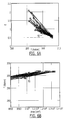
- FIGS. 5A and 5B are graphical representations of a temperature optimization process and the Monte Carlo estimates of the emissivity, area and temperature of an object as determined in accordance with one embodiment of the present invention relative to the actual emissivity, area and temperature of the object;
- FIGS. 6A , 6 B and 6 C are graphical representations of the emissivity and temperature covariance, temperature and area covariance and emissivity and area covariance, respectively, as determined in accordance with one embodiment of the present invention relative to the actual emissivity, area and temperature of the object.
- FIG. 3 a block diagram of an apparatus 20 for determining the emissivity, area and temperature of an object is depicted.
- these applications may include ballistic missile defense and tactical air defense scenarios, wind tunnel testing, medical thermography, observational astronomy, astrophysics or the like.
- the apparatus 20 includes a sensor 22 and an associated processor 24 .
- the sensor includes a detector having an associated focal plane array.
- the processor can be comprised of any one or more of a plurality of different computing devices, including a server, a workstation, a personal computer or the like, typically operating under software control.
- the sensor 22 is configured to detect the radiant intensity of signals within at least three distinct wavebands. Typically, each of the wavebands lies within the infrared spectrum. Although the sensor may be configured to detect signals having a variety of different wavelengths, the sensor of one embodiment is configured to detect three distinct wavebands, namely, a first waveband centered at 6 microns, a second waveband centered at 11.5 microns and a third waveband centered at 25 microns. In this example, each waveband has a bandwidth of 1 micron. As should be apparent, the apparatus 20 of other embodiments of the present invention may include sensors that are configured to detect more than three wavebands, to detect wavebands centered at different wavelengths and to have wavebands having different bandwidths.
- the sensor 22 may also be defined by a variety of other parameters, which will generally be predefined for a particular implementation.
- the sensor is also generally defined by a slant range (R), an optics area (A), a quantum efficiency (QE), a total integration time (Tint) and an analog integration time (tintwell).
- the slant range R is 1070 ⁇ 10 5 cm and the optics area A is ⁇ /4 ⁇ 45 2 cm 2 .
- the quantum efficiency which is a measure of the responsivity of the detector in terms of converting incoming photons to electrons, is 0.7 electrons/photons.
- the analog integration time (tintwell) of this example may be one millisecond which is defined by the size of the capacitor that initially accumulates the electrons generated by the detector.
- the total integration time (Tint) may be 10 milliseconds resulting from the collection of ten consecutive frames from the analog capacitor.
- an object may be defined in terms of its emissivity, area and temperature.
- the total source-based intensity of an object that is measured by the sensor can be mathematically defined in terms of the emissivity, area and temperature of the object.
- J 2 e*A*N 2+(1 ⁇ e )* A*B 2*
- F J 3 e*A*N 3+(1 ⁇ e )* A*B 3* F wherein the suffixes 1 , 2 and 3 designate the first, second and third wavebands, respectively.
- the total source-based intensity is based upon the emissivity e and the area A of the object. Additionally, the total source-based intensity is based upon both the object radiance N which is a function of object temperature T and the background radiance B. By taking into account not only the object radiance N, but also the background radiance B, the foregoing equations include both emission and reflectance components. As such, the inclusion of a reflectance component reduces or eliminates the bias in the resulting values of emissivity, area and temperature which are determined in accordance with embodiments of the present invention. Finally, the total source-based intensity is also based upon the geometric view factor F which is a predefined constant, such as about 0.5 for a particular sensor 22 .
- the Planck emission function therefore determines the radiance at a particular wavelength lam and a particular temperature T in kelvin with units of watts/cm 2 /steradian.
- C 1 and C 2 are Planck constants with C 1 equaling 1.191 ⁇ 10 ⁇ 12 watt cm 2 /steradian and C 2 equaling 1.438 cm kelvin and dlam is a small wavelength pass band centered at lam in units of cm.
- the Planck emission function is a function of wavelength lam which, in turn, is defined as the center wavelength of a respective waveband under evaluation, such as 6 microns, 11.5 microns and 25 microns for the first, second and third wavebands, respectively, of the example of the sensor 22 described above.
- the Planck emission function is a function of the temperature of the object under consideration. Since the target object and the background object will likely have different temperatures, the corresponding Planck emission functions for the target object and the background object which constitute the object radiance N and the background radiance B in the foregoing equations will also be different.
- the background object may have a temperature of 250 Kelvin and the target object may have a temperature of 300 Kelvin.
- the equations which define the total source-based intensity are therefore not only dependent upon the emissivity e and the area A of the object, but also the temperature T of the object since the Planck emission function which defines the object radiance N is dependent upon the temperature of the object.
- a sensor 22 since a sensor 22 introduces noise into every measurement, the measurement of the sensor will not only include the total source-based intensity, but will also include some amount of noise.
- a sensor such as an infrared sensor, generally includes shot noise, Johnson noise, readout noise and focal plane non-uniformity residuals.
- the shot noise may be dependent upon various parameters which define the sensor. In this regard, the shot noise may be dependent upon the detector area A d in cm 2 , a focal ratio Fstop, the emissivity of the optics Emoptic and the temperature of the optics Toptic in kelvin.
- the background emitted photoconductive shot noise may be determined, in one example, as follows:
- E 1 is the photon energy in Joules units and is specified by the mean wavelength lam 1 according to h c/lam 1 where h is Planck's constant 6.625 ⁇ 10 ⁇ 34 watt sec 2 , c is the speed of light 2.99793 ⁇ 10 10 cm/second and lam 1 is the mean wavelength in cm for band 1 .
- a signal to noise ratio SNR may be determined for signals received by the sensor 22 within a respective waveband (as designated by a suffix of 1, 2 or 3 for the first, second and third wavebands, respectively).
- the SNR for signals within the first waveband may be expressed as follows:
- the noise components generally vary and may be defined, for example, by a distribution function.
- a number of different trials designated i may be conducted with each trial permitting the noise components to have different random values.
- the signal to noise ratio that is defined above reflects the signal to noise ratio for signals received with a first waveband during trial i.
- the trials may be defined in various manners, the methods and apparatus 20 of one embodiment utilize Monte Carlo simulation for determining the contributions of each noise component during each of a plurality of different trials, such as trials of 64, 128, 256, 512 and so forth, in accordance with the random selection of noise values from respective statistical distributions.
- the denominator is an expression of the noise during a particular trial i, while the numerator represents a simulated measurement nJ 1 i by the sensor 22 within the first passband during trial i in electron units.
- the simulated measurement of the sensor nJ 1 i includes the expected contribution from the object as well as the sensor noise that is added thereto.
- a simulated object can be defined having a predefined emissivity, area and temperature and being at a predefined range relative to the sensor. Based upon the foregoing characteristics, the radiant intensity detected by the sensor from the object may be determined.
- the additive sensor noise may be determined as described above in accordance with, for example, a Monte Carlo simulation based upon the contributions from the various noise components, that is, Johnson noise, shot noise, readout noise and non-uniform residuals.
- the sum of the expected contribution from the object and the additive sensor noise comprises the simulated sensor measurement nJ 1 i .
- the determination of the emissivity, the area and the temperature of an object are generally determined in terms of electron counts, as opposed to in terms of photons.
- the total source-based intensity J may be converted from photons (in terms of watts/steradian) to electrons by multiplication with a conversion factor.
- the conversion factor is dependent upon the wavelength of the signals detected by the sensor 22 and, as such, a separate conversion factor is generally utilized in conjunction with each of the different wavebands supported by a sensor.
- a conversion factor associated with a first waveband 1 can be expressed as follows:
- R is the range between the object and the sensor in cm
- Aoptics is the collection area of the telescope in cm 2
- QE is the quantum efficiency of the detector in electrons per photon
- Tint is the photon integration time in seconds
- ⁇ 1 is the total transmittance, that is, the cumulative transmittance through the atmosphere and through the optics and any filters of the sensor in band 1 .
- the emissivity and the area of an object may be determined as a function of the temperature of the object.
- the processor 24 initially determines a simulated measurement of the radiant intensity detected by the sensor 22 for signals arriving in each of a first waveband 1 , a second waveband 2 and a third waveband 3 . These simulated measurements may be based upon a number of predefined parameters defining the emissivity, area, temperature and range of the object and may be converted to electron units by multiplication with a respective conversion factor.
- the simulated measurement of the sensor for signals within the first waveband, the second waveband and the third waveband may be designated as nJ 1 i , nJ 2 i and nJ 3 i , respectively, wherein the subscript references a particular trial or simulation i.
- the processor 24 then forms ratios of different pairs of the simulated measurements of radiant intensity, thereby defining ratios nJ 1 /nJ 2 , nJ 1 /nJ 3 and nJ 2 /nJ 3 , as shown in block 32 .
- the processor 24 may define the emissivity of the object in terms of the temperature of the object.
- the processor may determine emissivity of the object as a function of the temperature of the object for each of the plurality of ratios, namely, nJ 1 /nJ 2 , nJ 1 /nJ 3 and nJ 2 /nJ 3 . See block 34 .
- the emissivity of the object for the ratio nJ 1 /nJ 2 can be defined as follows:
- F is a predefined form factor
- B 1 and B 2 are the Planck emission functions evaluated at the temperature of a background element for signals in the first and second wavebands, respectively
- NN 1 and NN 2 are the Planck emission functions evaluated at the temperature k of the object for signals in the first and second wavebands, respectively, at a temperature k.
- the processor 24 also determines the area of the object as a function of the temperature of the object for each of the plurality of the ratios, such as nJ 1 /nJ 2 , nJ 1 /nJ 3 and nJ 2 /nJ 3 . See block 36 .
- the area of the object is based upon the emissivity of the object as determined for a respective ratio and the measure of radiant intensity of the object at a wavelength other than the wavelengths associated with the respective ratio.
- the area of the object which is based upon the ratio of nJ 1 /nJ 2 may be designated as AA 3 and expressed as follows:
- AA 3 i,k is the area of the object for trial i at temperature k. Similar expressions for the area of the object based upon each of the other ratios, such as area AA 2 based upon the emissivity of the object premised upon the ratio nJ 1 /nJ 3 and area AA 1 based upon the emissivity premised upon the ratio nJ 2 /nJ 3 , may be similarly developed.
- the processor 24 may determine the temperature of the object based upon the measure of radiant intensity of the object at each of the first, second and third wavelengths and further based on the emissivity and the area of the object as determined as a function of the temperature of the object. See block 38 of FIG. 4 .
- the temperature of the object is determined by the processor in one embodiment based upon minimizing a sum of squared residuals SOS between a simulated measure of the intensity of the object and a model of the radiant intensity of the object with the model of the radiant intensity of the object being based upon the emissivity and the area of the object at a pre defined temperature.
- AA i,k is the derived area of the object during trial i at temperature k index
- eeps i,k is the derived emissivity at the same temperature k index
- PlanckB is the assumed known background Planck radiance, PlanckB.
- sumJ i is the sum of the simulated measures of the radiant intensity of the object during trial i at each of the plurality (that is, 3) of wavebands as set forth below in conjunction with an embodiment having first, second and third wavebands. Conversion factors for watts per steradian to electron counts per detector are also assumed.
- sum nJ i : nJ 1 i +nJ 2 i +nJ 3 i
- B 1 , B 2 and B 3 are the known background radiance in the first, second and third sensor bands, respectively, in units of watts/cm 2 /steradian.
- the processor 24 may determine the sum of squared residuals SOS; for a variety of temperatures k.
- FIG. 5A provides a graphical representation of the relationship of the sum of squared residuals SOS i for Monte Carlo trial #12 for a variety of temperatures k from 290 to 310 kelvin.
- the processor may define the temperature to be the best temperature which minimizes the sum of squared residuals (in the case in FIG. 5A the best temperature is estimated to be 300 kelvin.) Based upon the defined temperature, the emissivity and the area of the object can then be determined in accordance with the foregoing equations for eeps and AA.
- FIG. 5A provides a graphical representation of the relationship of the sum of squared residuals SOS i for Monte Carlo trial #12 for a variety of temperatures k from 290 to 310 kelvin.
- the processor may define the temperature to be the best temperature which minimizes the sum of squared residuals (in the case in FIG. 5A the best temperature is estimated to be 300
- 5B shows the estimated emissivity eeps and object area AA based on the best temperature Tbest as for the full range of Monte Carlo trials from 1 to 64 and compares their estimates with the input truth, i.e., actual, values shown as dash dot lines. It is noted that the mean estimates of all the parameters are visually unbiased (i.e., estimates are evenly scattered about the truth), unlike biased two color temperature and emissivity area product algorithms which do not take into account reflected radiation.
- the processor 24 may repeat the determination of the emissivity, area and temperature of an object for a plurality of different trials, each of which may define the sensor noise contributions somewhat differently based upon the distributions associated with each noise component. See block 40 of FIG. 4 .
- the processor can then average the values of the emissivity, area and temperature determined for the plurality of trials as shown in block 42 .
- the methods and apparatus 20 of embodiments of the present invention can provide accurate estimations of the emissivity, area and temperature of an object with little, if any, bias.
- the estimations of the emissivity, area and temperature closely approximate the actual emissivity, area and temperature of the object and, as a result, of the relatively uniform scattering of the estimations about the actual values, the average values of the emissivity, area and temperature even more closely approximate the actual emissivity, area and temperature of the object.
- the average estimated emissivity is 0.879 and the standard deviation of the estimated emissivity is 0.348.
- the average estimated area is 9.952 ⁇ 10 3 cm 2 and the standard deviation of the estimated area is 1.975 ⁇ 10 3 cm 2 .
- the average estimated temperature is 300.188 Kelvin and the standard deviation of the estimated temperature is 4.528 Kelvin.
- FIGS. 6A , 6 B and 6 C Other graphical representations of the estimated emissivity, area and temperature relative to the actual emissivity, area and temperature are reflected in FIGS. 6A , 6 B and 6 C.
- FIG. 6A depicts the emissivity and temperature covariance
- FIG. 6B depicts the temperature and area covariance
- FIG. 6C depicts the emissivity and area covariance.
- rectangle 50 represents the actual values
- the other lines represent the estimated values with the scattering of the estimated values attributable, at least in part, to sensor noise contributions, which may, of course, be reduced by the use of a sensor having lower noise characteristics.
- the apparatus 20 is typically embodied by a processor 24 and an associated memory device 26 , both of which are commonly comprised by a computer or the like.
- the method of embodiments of the present invention can be performed by the processor manipulating data stored by the memory device.
- the apparatus can also include a display 28 for presenting information relative to performing embodiments of the method of the present invention, including information relating to the emissivity, area and temperature of an object as determined according to embodiments of the present invention.
- the apparatus can further include a printer.
- the apparatus 20 can include a means for locally or remotely transferring the information relative to performing embodiments of the method of the present invention.
- the apparatus can include a modem to transfer information to other computers or the like.
- the apparatus can include an interface to a network, such as a local area network (LAN), and/or a wide area network (WAN).
- the computer can include an Ethernet Personal Computer Memory Card International Association (PCMCIA) card configured to transmit and receive information to and from a LAN, WAN or the like.
- PCMCIA Personal Computer Memory Card International Association
- the apparatus 20 generally operates under control of a computer program product.
- the computer program product for performing the methods of embodiments of the present invention includes a computer-readable storage medium, such as the memory device 26 , and computer-readable program code portions, such as a series of computer instructions, embodied in the computer-readable storage medium.
- FIG. 4 is a flowcharts of method, apparatus and program products according to exemplary embodiments of the present invention. It will be understood that each block or step of the flowchart, and combinations of blocks in the flowchart, can be implemented by computer program instructions. These computer program instructions may be loaded onto a computer or other programmable apparatus, such as processor 24 , to produce a machine, such that the instructions which execute on the computer or other programmable apparatus create means for implementing the functions specified in the flowchart block(s) or step(s).
- These computer program instructions may also be stored in a computer-readable memory, such as the memory device 26 , that can direct a computer or other programmable apparatus to function in a particular manner, such that the instructions stored in the computer-readable memory produce an article of manufacture including instruction means which implement the function specified in the flowchart block(s) or step(s).
- the computer program instructions may also be loaded onto a computer or other programmable apparatus to cause a series of operational steps to be performed on the computer or other programmable apparatus to produce a computer implemented process such that the instructions which execute on the computer or other programmable apparatus provide steps for implementing the functions specified in the flowchart block(s) or step(s).
- blocks or steps of the flowchart support combinations of means for performing the specified functions, combinations of steps for performing the specified functions and program instruction means for performing the specified functions. It will also be understood that each block or step of the flowchart, and combinations of blocks or steps in the flowchart, can be implemented by special purpose hardware-based computer systems which perform the specified functions or steps, or combinations of special purpose hardware and computer instructions.
Abstract
Description
J1=e*A*N1+(1−e)*A*B1*F
J2=e*A*N2+(1−e)*A*B2*F
J3=e*A*N3+(1−e)*A*B3*F
wherein the
wherein E1 serves to convert the units from electrons to photons. In this regard, E1 is the photon energy in Joules units and is specified by the mean wavelength lam1 according to h c/lam1 where h is Planck's constant 6.625×10⁻³⁴ watt sec2, c is the speed of light 2.99793×1010 cm/second and lam1 is the mean wavelength in cm for
wherein R is the range between the object and the sensor in cm, Aoptics is the collection area of the telescope in cm2, QE is the quantum efficiency of the detector in electrons per photon, Tint is the photon integration time in seconds and τ1 is the total transmittance, that is, the cumulative transmittance through the atmosphere and through the optics and any filters of the sensor in
wherein eeps12 i,k represents the emissivity of the object with the suffix 12 designating that the emissivity is based upon the ratio nJ1/nJ2 and the subscripts i,k representing that the emissivity is for trial i and at temperature k. As described above, F is a predefined form factor, B1 and B2 are the Planck emission functions evaluated at the temperature of a background element for signals in the first and second wavebands, respectively, and NN1 and NN2 are the Planck emission functions evaluated at the temperature k of the object for signals in the first and second wavebands, respectively, at a temperature k. Although the foregoing equation represents the emissivity of the object for the ratio of nJ1/nJ2, similar expressions for the emissivity of the object as a function of each of the other ratios are also developed.
SOS i,k:=[sumnJ i−sum(AA i,k(eeps i,kplanckmodeli,k+(1− eeps i,k)planckB))]2
sumnJ i :=nJ1i +nJ2i +nJ3i
sumnplanckmodeli,k :=AA i,k {[eeps i,k NN1k+(1−eeps i,k)B1F]factorJton1+[eeps i,k NN2k+(1−eeps i,k)B2F]factorJton2+[eeps i,k NN3k+(1−eeps i,k)B3F]factorJton3}
In the foregoing equation, B1, B2 and B3 are the known background radiance in the first, second and third sensor bands, respectively, in units of watts/cm2/steradian.
Claims (18)
Priority Applications (1)
| Application Number | Priority Date | Filing Date | Title |
|---|---|---|---|
| US11/951,698 US8050884B2 (en) | 2007-12-06 | 2007-12-06 | Method and apparatus for determining the emissivity, area and temperature of an object |
Applications Claiming Priority (1)
| Application Number | Priority Date | Filing Date | Title |
|---|---|---|---|
| US11/951,698 US8050884B2 (en) | 2007-12-06 | 2007-12-06 | Method and apparatus for determining the emissivity, area and temperature of an object |
Publications (2)
| Publication Number | Publication Date |
|---|---|
| US20100256945A1 US20100256945A1 (en) | 2010-10-07 |
| US8050884B2 true US8050884B2 (en) | 2011-11-01 |
Family
ID=42826932
Family Applications (1)
| Application Number | Title | Priority Date | Filing Date |
|---|---|---|---|
| US11/951,698 Expired - Fee Related US8050884B2 (en) | 2007-12-06 | 2007-12-06 | Method and apparatus for determining the emissivity, area and temperature of an object |
Country Status (1)
| Country | Link |
|---|---|
| US (1) | US8050884B2 (en) |
Cited By (3)
| Publication number | Priority date | Publication date | Assignee | Title |
|---|---|---|---|---|
| US20140286376A1 (en) * | 2013-03-21 | 2014-09-25 | Horiba, Ltd. | Thermometer |
| DE102014117388A1 (en) * | 2014-11-27 | 2016-06-02 | Aixtron Se | Method for calibrating a pyrometer arrangement of a CVD or PVD reactor |
| US10564040B2 (en) | 2011-08-09 | 2020-02-18 | The Boeing Company | Method and apparatus for identifying information about spatially unresolved objects in hyperspectral images |
Families Citing this family (15)
| Publication number | Priority date | Publication date | Assignee | Title |
|---|---|---|---|---|
| US8345775B2 (en) * | 2008-04-14 | 2013-01-01 | Apple Inc. | System and method for masking visual compression artifacts in decoded video streams |
| WO2014067549A1 (en) * | 2012-10-29 | 2014-05-08 | Ptc Innovation Ab | A method for measuring temperature |
| DE112014006200T5 (en) * | 2014-01-16 | 2016-10-27 | Hewlett-Packard Development Company, L.P. | Temperature determination based on emissivity |
| CN105916661B (en) | 2014-01-16 | 2019-09-10 | 惠普发展公司,有限责任合伙企业 | Generate three dimensional object |
| US10252474B2 (en) | 2014-01-16 | 2019-04-09 | Hewlett-Packard Development Company, L.P. | Temperature determination based on emissivity |
| EP3094469B1 (en) | 2014-01-16 | 2019-11-13 | Hewlett-Packard Development Company, L.P. | Generating a three-dimensional object |
| CN105916665B (en) | 2014-01-16 | 2019-11-05 | 惠普发展公司,有限责任合伙企业 | Generate three dimensional object |
| CN105911079B (en) * | 2016-05-10 | 2018-06-01 | 安徽工业大学 | A kind of device tested available for emissivity under radiation field |
| JP6690092B2 (en) * | 2016-07-27 | 2020-04-28 | 富士通株式会社 | Heat source detection device, heat source detection method, and heat source detection program |
| JP7024981B2 (en) * | 2017-08-01 | 2022-02-24 | シグマ ラボズ,インコーポレイテッド | Systems and methods for measuring radiant thermal energy during additive manufacturing operations |
| DE102018127678A1 (en) | 2017-11-07 | 2019-05-09 | Sigma Labs, Inc. | Methods and systems for quality feedback and quality control in additive manufacturing processes |
| US11260454B2 (en) | 2017-11-07 | 2022-03-01 | Sigma Labs, Inc. | Correction of non-imaging thermal measurement devices |
| CN114749789A (en) | 2018-02-21 | 2022-07-15 | 西格马实验室公司 | Systems and methods for additive manufacturing |
| WO2019165111A1 (en) | 2018-02-21 | 2019-08-29 | Sigma Labs, Inc. | Systems and methods for measuring radiated thermal energy during an additive manufacturing operation |
| CN115773824B (en) * | 2023-02-13 | 2023-04-28 | 南方科技大学 | Temperature correction method and temperature correction device for concave structure object |
Citations (5)
| Publication number | Priority date | Publication date | Assignee | Title |
|---|---|---|---|---|
| US5021980A (en) * | 1989-02-21 | 1991-06-04 | Lsi Logic Corporation | Remote measurement of temperature |
| US5153563A (en) * | 1989-08-23 | 1992-10-06 | Nippon Mining Co., Ltd. | Fire sensing system, process for sensing fire and environment monitor |
| US5231595A (en) * | 1983-06-06 | 1993-07-27 | Minolta Camera Kabushiki Kaisha | Pyrometer |
| US20050045825A1 (en) | 2003-08-29 | 2005-03-03 | Murata Ronald N. | Methods and apparatus for infrared resolution of closely-spaced objects |
| WO2007093744A2 (en) | 2006-02-17 | 2007-08-23 | Cea | Method and device for characterizing, using active pyrometry, a thin-layer material arranged on a substrate |
-
2007
- 2007-12-06 US US11/951,698 patent/US8050884B2/en not_active Expired - Fee Related
Patent Citations (6)
| Publication number | Priority date | Publication date | Assignee | Title |
|---|---|---|---|---|
| US5231595A (en) * | 1983-06-06 | 1993-07-27 | Minolta Camera Kabushiki Kaisha | Pyrometer |
| US5021980A (en) * | 1989-02-21 | 1991-06-04 | Lsi Logic Corporation | Remote measurement of temperature |
| US5153563A (en) * | 1989-08-23 | 1992-10-06 | Nippon Mining Co., Ltd. | Fire sensing system, process for sensing fire and environment monitor |
| US20050045825A1 (en) | 2003-08-29 | 2005-03-03 | Murata Ronald N. | Methods and apparatus for infrared resolution of closely-spaced objects |
| WO2007093744A2 (en) | 2006-02-17 | 2007-08-23 | Cea | Method and device for characterizing, using active pyrometry, a thin-layer material arranged on a substrate |
| US20100100352A1 (en) * | 2006-02-17 | 2010-04-22 | Pierre-Yves Thro | Method and Device for Characterizing, Using Active Pyrometry, a Thin-Layer Material Arranged on a Substrate |
Non-Patent Citations (2)
| Title |
|---|
| "Mosaic Signal Processing in Nuclear Environments (U)"; Final Technical Report; Oct. 1984; Prepared for: The Ballistic Missile Defense; Advanced Technology Center; Huntsville, Alabama; Contract Monitor: F.M. Hoke. |
| Spitzberg, R.M., "Tutorial on Target Phenomenology and Optical Discrimination for Midcourse Sensors"; MIT Lincoln Laboratory; NMD Discrimination Working Group; Nov. 14, 2001. |
Cited By (4)
| Publication number | Priority date | Publication date | Assignee | Title |
|---|---|---|---|---|
| US10564040B2 (en) | 2011-08-09 | 2020-02-18 | The Boeing Company | Method and apparatus for identifying information about spatially unresolved objects in hyperspectral images |
| US20140286376A1 (en) * | 2013-03-21 | 2014-09-25 | Horiba, Ltd. | Thermometer |
| US9506807B2 (en) * | 2013-03-21 | 2016-11-29 | Horiba, Ltd. | Optical gas temperature sensor |
| DE102014117388A1 (en) * | 2014-11-27 | 2016-06-02 | Aixtron Se | Method for calibrating a pyrometer arrangement of a CVD or PVD reactor |
Also Published As
| Publication number | Publication date |
|---|---|
| US20100256945A1 (en) | 2010-10-07 |
Similar Documents
| Publication | Publication Date | Title |
|---|---|---|
| US8050884B2 (en) | Method and apparatus for determining the emissivity, area and temperature of an object | |
| US20200124525A1 (en) | Gas leak emission quantification with a gas cloud imager | |
| EP1303742B1 (en) | Spectral drift and correction technique for hyperspectral imaging systems | |
| US7887234B2 (en) | Maximum blade surface temperature estimation for advanced stationary gas turbines in near-infrared (with reflection) | |
| Syariz et al. | Spectral-consistent relative radiometric normalization for multitemporal Landsat 8 imagery | |
| EP0456412B1 (en) | Temperature measuring method using infrared sensors and processor | |
| CN107894284B (en) | A kind of infrared camera wave band comparative approach of combination detection efficiency | |
| Savino et al. | Free emissivity temperature investigations by dual color applied physics methodology in the mid-and long-infrared ranges | |
| CN103776532B (en) | A kind of hyperspectral imager index optimization method based on remote sensing application | |
| CN103913237B (en) | The three accurate temp measuring methods of wave band infra-red radiation | |
| Bley et al. | A threshold-based cloud mask for the high-resolution visible channel of Meteosat Second Generation SEVIRI | |
| CN110186566A (en) | Two-dimentional true temperature field imaging method and system based on the multispectral thermometric of light-field camera | |
| CN105043555B (en) | A kind of method for calculating spectral emissivity and true temperature | |
| CN115222707A (en) | Full-spectrum hyperspectral earth remote sensing imaging measurement uncertainty analysis method | |
| CN205642634U (en) | Dual wavelength temperature field imaging device and system based on compressed sensing | |
| Liu et al. | Vicarious calibration of the formosat-2 remote sensing instrument | |
| Meola et al. | Modeling, development, and testing of a shortwave infrared supercontinuum laser source for use in active hyperspectral imaging | |
| Yu et al. | Study on CCD temperature measurement method without channel proportional coefficient calibration | |
| CN114061766A (en) | Multispectral reconstruction temperature measuring device and method in particle combustion process | |
| CN113945282A (en) | Infrared remote sensing satellite temperature inversion precision index distribution system and method | |
| CN105784626A (en) | Atmospheric pollutant self-adaptive identification method and system based on infrared spectrum imaging technology | |
| Dempsey et al. | A new era of wide-field submillimetre imaging: on-sky performance of SCUBA-2 | |
| Paproth et al. | MERTIS: system theory and simulation | |
| Sentenac et al. | Evaluation of a charge-coupled-device-based video sensor for aircraft cargo surveillance | |
| McComas | Toolkit for remote-sensing analysis, design, evaluation, and simulation |
Legal Events
| Date | Code | Title | Description |
|---|---|---|---|
| AS | Assignment |
Owner name: THE BOEING COMPANY, ILLINOIS Free format text: ASSIGNMENT OF ASSIGNORS INTEREST;ASSIGNOR:MURATA, RONALD N.;REEL/FRAME:020207/0165 Effective date: 20071205 |
|
| ZAAA | Notice of allowance and fees due |
Free format text: ORIGINAL CODE: NOA |
|
| ZAAB | Notice of allowance mailed |
Free format text: ORIGINAL CODE: MN/=. |
|
| ZAAA | Notice of allowance and fees due |
Free format text: ORIGINAL CODE: NOA |
|
| ZAAB | Notice of allowance mailed |
Free format text: ORIGINAL CODE: MN/=. |
|
| STCF | Information on status: patent grant |
Free format text: PATENTED CASE |
|
| FEPP | Fee payment procedure |
Free format text: PAYOR NUMBER ASSIGNED (ORIGINAL EVENT CODE: ASPN); ENTITY STATUS OF PATENT OWNER: LARGE ENTITY |
|
| FPAY | Fee payment |
Year of fee payment: 4 |
|
| MAFP | Maintenance fee payment |
Free format text: PAYMENT OF MAINTENANCE FEE, 8TH YEAR, LARGE ENTITY (ORIGINAL EVENT CODE: M1552); ENTITY STATUS OF PATENT OWNER: LARGE ENTITY Year of fee payment: 8 |
|
| FEPP | Fee payment procedure |
Free format text: MAINTENANCE FEE REMINDER MAILED (ORIGINAL EVENT CODE: REM.); ENTITY STATUS OF PATENT OWNER: LARGE ENTITY |
|
| LAPS | Lapse for failure to pay maintenance fees |
Free format text: PATENT EXPIRED FOR FAILURE TO PAY MAINTENANCE FEES (ORIGINAL EVENT CODE: EXP.); ENTITY STATUS OF PATENT OWNER: LARGE ENTITY |
|
| STCH | Information on status: patent discontinuation |
Free format text: PATENT EXPIRED DUE TO NONPAYMENT OF MAINTENANCE FEES UNDER 37 CFR 1.362 |
|
| FP | Lapsed due to failure to pay maintenance fee |
Effective date: 20231101 |