US8050259B2 - Method and apparatus of precedence identification for real time services - Google Patents
Method and apparatus of precedence identification for real time services Download PDFInfo
- Publication number
- US8050259B2 US8050259B2 US11/474,197 US47419706A US8050259B2 US 8050259 B2 US8050259 B2 US 8050259B2 US 47419706 A US47419706 A US 47419706A US 8050259 B2 US8050259 B2 US 8050259B2
- Authority
- US
- United States
- Prior art keywords
- packet
- destination
- hops
- data packet
- packets
- Prior art date
- Legal status (The legal status is an assumption and is not a legal conclusion. Google has not performed a legal analysis and makes no representation as to the accuracy of the status listed.)
- Active, expires
Links
- 238000000034 method Methods 0.000 title claims abstract description 18
- 235000008694 Humulus lupulus Nutrition 0.000 claims abstract description 36
- 239000000872 buffer Substances 0.000 claims description 18
- 230000008569 process Effects 0.000 claims description 3
- 238000010586 diagram Methods 0.000 description 10
- 230000005540 biological transmission Effects 0.000 description 4
- 238000007689 inspection Methods 0.000 description 4
- 230000006399 behavior Effects 0.000 description 3
- 238000004590 computer program Methods 0.000 description 3
- 230000007246 mechanism Effects 0.000 description 3
- 230000008901 benefit Effects 0.000 description 2
- 230000007423 decrease Effects 0.000 description 2
- 230000001934 delay Effects 0.000 description 2
- 239000000284 extract Substances 0.000 description 1
- 230000006870 function Effects 0.000 description 1
- 230000000977 initiatory effect Effects 0.000 description 1
- 230000003993 interaction Effects 0.000 description 1
- 239000003550 marker Substances 0.000 description 1
- 238000012986 modification Methods 0.000 description 1
- 230000004048 modification Effects 0.000 description 1
Images


Classifications
-
- H—ELECTRICITY
- H04—ELECTRIC COMMUNICATION TECHNIQUE
- H04L—TRANSMISSION OF DIGITAL INFORMATION, e.g. TELEGRAPHIC COMMUNICATION
- H04L65/00—Network arrangements, protocols or services for supporting real-time applications in data packet communication
- H04L65/1066—Session management
- H04L65/1101—Session protocols
-
- H—ELECTRICITY
- H04—ELECTRIC COMMUNICATION TECHNIQUE
- H04L—TRANSMISSION OF DIGITAL INFORMATION, e.g. TELEGRAPHIC COMMUNICATION
- H04L45/00—Routing or path finding of packets in data switching networks
-
- H—ELECTRICITY
- H04—ELECTRIC COMMUNICATION TECHNIQUE
- H04L—TRANSMISSION OF DIGITAL INFORMATION, e.g. TELEGRAPHIC COMMUNICATION
- H04L45/00—Routing or path finding of packets in data switching networks
- H04L45/20—Hop count for routing purposes, e.g. TTL
-
- H—ELECTRICITY
- H04—ELECTRIC COMMUNICATION TECHNIQUE
- H04L—TRANSMISSION OF DIGITAL INFORMATION, e.g. TELEGRAPHIC COMMUNICATION
- H04L45/00—Routing or path finding of packets in data switching networks
- H04L45/302—Route determination based on requested QoS
- H04L45/306—Route determination based on the nature of the carried application
- H04L45/3065—Route determination based on the nature of the carried application for real time traffic
-
- H—ELECTRICITY
- H04—ELECTRIC COMMUNICATION TECHNIQUE
- H04L—TRANSMISSION OF DIGITAL INFORMATION, e.g. TELEGRAPHIC COMMUNICATION
- H04L47/00—Traffic control in data switching networks
- H04L47/10—Flow control; Congestion control
-
- H—ELECTRICITY
- H04—ELECTRIC COMMUNICATION TECHNIQUE
- H04L—TRANSMISSION OF DIGITAL INFORMATION, e.g. TELEGRAPHIC COMMUNICATION
- H04L47/00—Traffic control in data switching networks
- H04L47/10—Flow control; Congestion control
- H04L47/24—Traffic characterised by specific attributes, e.g. priority or QoS
- H04L47/2416—Real-time traffic
-
- H—ELECTRICITY
- H04—ELECTRIC COMMUNICATION TECHNIQUE
- H04L—TRANSMISSION OF DIGITAL INFORMATION, e.g. TELEGRAPHIC COMMUNICATION
- H04L47/00—Traffic control in data switching networks
- H04L47/10—Flow control; Congestion control
- H04L47/28—Flow control; Congestion control in relation to timing considerations
- H04L47/286—Time to live
-
- H—ELECTRICITY
- H04—ELECTRIC COMMUNICATION TECHNIQUE
- H04L—TRANSMISSION OF DIGITAL INFORMATION, e.g. TELEGRAPHIC COMMUNICATION
- H04L47/00—Traffic control in data switching networks
- H04L47/10—Flow control; Congestion control
- H04L47/35—Flow control; Congestion control by embedding flow control information in regular packets, e.g. piggybacking
-
- H—ELECTRICITY
- H04—ELECTRIC COMMUNICATION TECHNIQUE
- H04L—TRANSMISSION OF DIGITAL INFORMATION, e.g. TELEGRAPHIC COMMUNICATION
- H04L65/00—Network arrangements, protocols or services for supporting real-time applications in data packet communication
- H04L65/80—Responding to QoS
-
- H—ELECTRICITY
- H04—ELECTRIC COMMUNICATION TECHNIQUE
- H04W—WIRELESS COMMUNICATION NETWORKS
- H04W28/00—Network traffic management; Network resource management
- H04W28/02—Traffic management, e.g. flow control or congestion control
- H04W28/10—Flow control between communication endpoints
-
- H—ELECTRICITY
- H04—ELECTRIC COMMUNICATION TECHNIQUE
- H04W—WIRELESS COMMUNICATION NETWORKS
- H04W8/00—Network data management
- H04W8/02—Processing of mobility data, e.g. registration information at HLR [Home Location Register] or VLR [Visitor Location Register]; Transfer of mobility data, e.g. between HLR, VLR or external networks
- H04W8/04—Registration at HLR or HSS [Home Subscriber Server]
Definitions
- the present invention relates generally to quality of service in Internet Protocol (IP) networks, and more specifically to prioritizing data packets in an IP network.
- IP Internet Protocol
- QoS Quality of service
- IP Internet Protocol
- IP packets can follow the standards defined by Internet Protocol version 4 (IPv4) (i.e., IPv4 packets) or Internet Protocol version 6 (IPv6) (i.e., IPv6 packets).
- IPv4 Internet Protocol version 4
- IPv6 Internet Protocol version 6
- FIG. 1 is a block diagram of an IPv4 packet header 100 including a Type of Service (TOS) field 104 .
- the TOS field 104 is for Internet service quality selection. The type of service is specified via parameters such as Precedence, Delay, Throughput, and Reliability.
- the IPv4 header 100 also includes a Time-To-Live (TTL) field 108 .
- TTL field 108 contains a value that indicates to a network router or switch whether or not the packet has been in the network too long and is to be discarded. For a number of reasons, packets may not get delivered to their destination in a reasonable length of time. For example, incorrect routing tables may cause a packet to loop between two routers endlessly. A solution is to discard the packet after a certain time.
- the initial TTL value 108 is set in an 8 bit field of the packet header. Since each router is required to subtract at least one count from the TTL field, the count is usually used to indicate the number of router hops the packet is allowed before it must be
- FIG. 2 is a block diagram of an IPv6 header 200 including a Traffic Class (TC) field 204 .
- the IPv6 header 200 also includes a Hop Limit field 208 .
- the Hop Limit field 208 indicates the maximum number of hops that the packet can travel before being discarded.
- the Hop Limit field 208 is similar to the TTL value in an IPv4 packet.
- FIG. 3( a ) provides more detail of the IPv4 TOS field 104 .
- the TOS field 104 includes a Precedence field 304 and a Priority field 306 .
- the Precedence field 304 is a field used to prioritize an IPv4 packet.
- the Precedence field 304 designates whether the network determines, using the Priority field 306 , the priority of a packet or whether the Priority field 306 is ignored and the network does not determine the priority of a packet.
- the Priority field 306 allows the network to take of advantage of various queuing and congestion control mechanisms that may exist within the network.
- FIG. 3( b ) provides more detail of the IPv6 TC field 204 .
- the TC field 204 is available for use by originating routers and/or forwarding routers to identify and distinguish between different classes or priorities of IPv6 packets.
- the TC field 204 is used to provide various forms of “differentiated service” for IPv6 packets.
- Differentiated Service Code Points (DSCP), or DiffServe is a marker in the header of each IP packet that prompts network routers to apply differentiated grades of service to various packet streams, forwarding them according to different Per-Hop Behaviors (PHBs). This enables Internet and other IP-based network service providers to offer differentiated levels of service to customers and their information streams.
- DiffServ has also been implemented in the TOS field of an IPv4 packet.
- IP header When a packet enters an IP router, its IP header is inspected. The inspection determines a next hop and a priority with which the packet is forwarded from the current router. The priority is determined by interpreting the Precedence field 304 and Priority field 306 for the TOS field 104 of an IPv4 packet and the Differentiated Service Code Points (DSCP) value in the TC field 204 of an IPv6 packet. If a packet's header fields do not provide enough guidance to determine its priority, a deep packet inspection is performed to gain more information from which a priority decision can be made.
- DSCP Differentiated Service Code Points
- a packet's priority affects when the packet is scheduled to be transmitted to its next hop.
- the task of packet scheduling is to associate a packet with a time slot (at a constant power, data rate, and through one shared channel).
- packet scheduling can be more general than that—its function is to schedule such resources as time slots, powers, data rates, channels, or a combination of them, when packets are transmitted.
- a wireless scheduler assigns time slots, powers, data rates, and/or channels to the packets for transmission.
- Real-time Transport Protocol is an Internet protocol for transmitting real-time data such as audio and video.
- RTP supports streaming data.
- the time that the packet is due at a destination router i.e., the packet's deadline
- Packets of an RTP voice stream may be encrypted. If the voice stream is encrypted, then the deadline cannot be retrieved from the packet.
- any method that involves packet inspection will typically not be effective because no additional knowledge of the importance of the packet data can be obtained due to the encryption.
- Wireless links are typically either the first or last link in the network.
- the majority of QoS is often determined by behavior of the last wireless hop node (e.g., router).
- the last wireless hop node will not typically be able to use a packet's header alone to determine the relative importance of a packet among packets of the same service ensemble (e.g., packets associated with a single Voice over Internet Protocol (VoIP) telephone call).
- VoIP Voice over Internet Protocol
- the present invention is a method and apparatus for transmitting a data packet from a source to a destination via a network path having a number of hops.
- the sum of a playback delay associated with the data packet and the number of hops are stored in a header of the data packet.
- the data packet is transmitted from the source to the destination via the network path.
- the sum of the playback delay and the number of hops is calculated at the source.
- the sum may be calculated at the destination.
- the data packet is processed (e.g., played by a wireless telephone) during a VoIP telephone call before the sum of the playback delay and the number of hops expires.
- the sum of the playback delay and the number of hops may be stored in the TTL field of the header of the packet.
- the number of hops can be determined by, for instance, the source pinging the destination.
- the priority of the data packet can be determined from the playback delay and the number of hops.
- FIG. 1 is a block diagram of a prior art IPv4 packet header
- FIG. 2 is a block diagram of a prior art IPv6 packet header
- FIG. 3( a ) is a block diagram of a prior art Type of Service (TOS) field of an IPv4 header of a packet;
- TOS Type of Service
- FIG. 3( b ) is a block diagram of a prior art Traffic Class (TC) field of an IPv6 header of a packet;
- TC Traffic Class
- FIG. 4 is a block diagram of a transmitting router communicating a packet to a destination router in accordance with an embodiment of the present invention
- FIG. 5 is a flowchart of the steps performed to schedule the deadline of a packet in accordance with an embodiment of the present invention
- FIG. 6 is a flowchart of the steps performed by the destination router to determine the priority of a packet received from the transmitting router in accordance with an embodiment of the present invention.
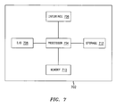
- FIG. 7 is a high level block diagram of a computer in accordance with an embodiment of the invention.
- FIG. 4 shows a block diagram of communications sent from a sending node 404 to a receiving node 406 .
- the sending node 404 and/or the receiving node 406 are wireless telephones.
- the sending node 404 transmits packets to a transmitting router 408 (e.g., a base station router (BSR)).
- BSR base station router
- the transmitting router 408 can set the TOS or TC field of a packet to be Diff Serv compliant.
- the transmitting router 408 sets the TTL value to a predetermined maximum (i.e., TTL MAX ).
- This predetermined maximum can be a parameter negotiated between the transmitting router 408 and a destination router 424 (e.g., a BSR) (TTL NEG ) (e.g., in a Session Initiation Protocol (SIP)/Session Description Protocol (SDP) session negotiation).
- the predetermined maximum can be a default maximum.
- the packet is then transmitted to a second hop 412 , a third hop 416 , and a fourth hop 420 .
- Each of these hops 412 , 416 , 420 can be, for example, routers or switches.
- Each router 412 , 416 , 420 subtracts one from the TTL field of the packet's header.
- the packet is then sent to the destination router 424 .
- the destination router 424 extracts the received TTL (i.e., TTL RX ).
- the destination router 424 determines the hop count.
- the destination router 424 includes a scheduler 428 .
- the scheduler 428 guarantees that a packet arrives at the receiving node 406 before its hop count is exhausted.
- the scheduler 428 uses the hop count to determine how much flexibility it has in scheduling the packet. Every packet time (i.e., a predetermined time interval associated with a packet), the scheduler 428 subtracts 1 from the hop count.
- an embodiment of the present invention uses the TOS or TC fields in conjunction with the TTL or Hop Limit fields.
- FIG. 5 shows a flowchart illustrating the steps performed in accordance with an embodiment of the invention to determine the deadline of a voice stream packet. Deep packet inspection is not needed to determine the deadline of a packet because of the use of the modified TTL (or Hop Limit) field.
- the number of hops required for the voice packets to travel from the transmitting router 408 to the destination router 424 over an IP network is determined in step 504 .
- the transmitting router 408 pings the destination router 424 to determine the number of hops. The reason for determining the number of hops is because the destination router 424 then uses the IP router hop count between the transmitting router 408 and the destination router 424 to determine the deadline of the packet.
- the time period needed to process the packet is determined by the destination router 424 .
- a typical VoIP application buffers incoming packets in a playout buffer and delays their playout in order to compensate for variable network delays (i.e., jitter). This allows the slowest packets to arrive in time to be played out.
- the length of a playback delay (i.e., the length of the playout buffer) imposed by the destination router 424 is determined in step 508 .
- the reason for determining the playout buffer length in the destination router 424 is to enable the determination of how many extra “virtual” hops need to be added to the hop count to indicate the deadline of the packet. Determining a “virtual” hop is adding an amount to the TTL field for the playout buffer that is equivalent to the amount added to the TTL field for a hop.
- the hop count between the transmitting router and the destination router is N hops
- the playout buffer in the destination router is X packets
- the hop count needs to be set to N+X.
- X represents the relative importance of the packet compared with other packets.
- the hop count remaining when the packet is received by the destination router is then used as an indicator to the scheduler of the deadline of a packet in step 512 .
- every IP router subtracts one from the hop count set by the transmitting router.
- the destination router receives a hop count of X. As described above, the destination router then uses this remaining hop count X as an indicator to the wireless channel scheduler of how much flexibility the scheduler has in scheduling the packet. Every packet time, the wireless channel scheduler subtracts 1 from X. If X is large, the wireless channel scheduler can use more aggressive scheduling mechanisms for delivering the packet at the terminal compared to small values of X. X represents the relative importance of the packet because, as X increases, the scheduler has more time before the packet has to be used. Similarly, as X decreases, the scheduler has less time before the packet has to be used. As a result, X represents the importance of the packet (i.e., the more important a packet is, the lower X is).
- the same process applies.
- the destination router 424 receives a packet from the receiving node 406 for transmission to the sending node 404 , the destination router 424 already “knows” what to set the packet's hop count to based on the packet(s) that the destination router 424 previously received from the transmitting router 408 . Once this hop count is set, the transmitting router 408 receives the packet and can determine, in step 512 , that the packet has, for example, a high priority and needs to be delivered to the sending node 404 quickly.
- FIG. 6 shows a flowchart of the steps performed by the destination router 424 upon receipt of a packet.
- the destination router 424 receives inbound packets from the IP network in step 604 and checks the TOS (or TC) field and the TTL (or Hop Limit) field in step 608 .
- the destination router 524 determines whether the TOS (or TC) field equals “immediate” or “priority” in step 612 . If the TOS field does not equal “immediate” or “priority” in step 612 , then the destination router 424 (i.e., the scheduler 428 ) uses “normal” priority handling methods in step 614 .
- Normal priority handling methods include having the packet traverse along a destination router's queue in the order of which the packet went onto the queue (e.g., when the TTL field is high enough such that the TTL field does not decrease down to zero before being sent out of the destination router 424 ).
- Computer 702 contains a processor 704 which controls the overall operation of computer 702 by executing computer program instructions which define such operation.
- the computer program instructions may be stored in a storage device 712 (e.g., magnetic disk) and loaded into memory 710 when execution of the computer program instructions is desired.
- Computer 702 also includes one or more interfaces 706 for communicating with other devices (e.g., locally or via a network).
- Computer 702 also includes input/output 708 which represents devices which allow for user interaction with the computer 702 (e.g., display, keyboard, mouse, speakers, buttons, etc.).
- FIG. 7 is a high level representation of some of the components of such a computer for illustrative purposes.
- computer 702 may represent the transmitting router and/or the receiving router of FIG. 4 .
- the processing steps described herein may also be implemented using dedicated hardware, the circuitry of which is configured specifically for implementing such processing steps. Alternatively, the processing steps may be implemented using various combinations of hardware and software. Also, the processing steps may take place in a computer or may be part of a larger machine.
Abstract
Description
Hops=TTL MAX −TTL RX
or the formula:
Hops=TTL NEG −TTL RX
Claims (20)
Priority Applications (6)
| Application Number | Priority Date | Filing Date | Title |
|---|---|---|---|
| US11/474,197 US8050259B2 (en) | 2006-06-23 | 2006-06-23 | Method and apparatus of precedence identification for real time services |
| CN2007800236281A CN101479998B (en) | 2006-06-23 | 2007-06-19 | Method and apparatus of precedence identification for real time services |
| PCT/US2007/014420 WO2008002440A2 (en) | 2006-06-23 | 2007-06-19 | Method and apparatus of precedence identification for real time services |
| JP2009515539A JP4782226B2 (en) | 2006-06-23 | 2007-06-19 | Priority identification method and apparatus for real-time service |
| EP07835845.4A EP2036278B1 (en) | 2006-06-23 | 2007-06-19 | Method and apparatus of precedence identification for real time services |
| KR1020087029757A KR101106027B1 (en) | 2006-06-23 | 2007-06-19 | Method and system for transmitting a data packet |
Applications Claiming Priority (1)
| Application Number | Priority Date | Filing Date | Title |
|---|---|---|---|
| US11/474,197 US8050259B2 (en) | 2006-06-23 | 2006-06-23 | Method and apparatus of precedence identification for real time services |
Publications (2)
| Publication Number | Publication Date |
|---|---|
| US20070297401A1 US20070297401A1 (en) | 2007-12-27 |
| US8050259B2 true US8050259B2 (en) | 2011-11-01 |
Family
ID=38805765
Family Applications (1)
| Application Number | Title | Priority Date | Filing Date |
|---|---|---|---|
| US11/474,197 Active 2029-10-15 US8050259B2 (en) | 2006-06-23 | 2006-06-23 | Method and apparatus of precedence identification for real time services |
Country Status (6)
| Country | Link |
|---|---|
| US (1) | US8050259B2 (en) |
| EP (1) | EP2036278B1 (en) |
| JP (1) | JP4782226B2 (en) |
| KR (1) | KR101106027B1 (en) |
| CN (1) | CN101479998B (en) |
| WO (1) | WO2008002440A2 (en) |
Cited By (2)
| Publication number | Priority date | Publication date | Assignee | Title |
|---|---|---|---|---|
| US20110149844A1 (en) * | 2009-12-21 | 2011-06-23 | Manipal Institute Of Technology | Multi-service adaptable routing protocol for wireless sensor networks |
| US20110258261A1 (en) * | 2010-04-15 | 2011-10-20 | Avaya Inc. | Phase based prioritization of ims signaling messages for overload throttling |
Families Citing this family (11)
| Publication number | Priority date | Publication date | Assignee | Title |
|---|---|---|---|---|
| US20060227774A1 (en) * | 2005-04-06 | 2006-10-12 | International Business Machines Corporation | Collective network routing |
| US7733773B2 (en) * | 2006-10-18 | 2010-06-08 | Telefonaktiebolaget Lm Ericsson (Publ) | Playout based delay scheduler |
| JP5076581B2 (en) * | 2007-03-23 | 2012-11-21 | 日本電気株式会社 | Optical communication system, node device, and service class setting method |
| KR20120005613A (en) * | 2010-07-09 | 2012-01-17 | 삼성전자주식회사 | Apparatus and method for reducing message overhead in wireless commincation system |
| EP3332522B8 (en) * | 2015-08-06 | 2019-07-31 | British Telecommunications public limited company | Data packet network |
| CN107612829B (en) * | 2016-07-12 | 2021-11-26 | 华为技术有限公司 | Method and device for acquiring path information of data message |
| EP3614526B1 (en) * | 2018-08-21 | 2024-01-03 | Schneider Electric IT Corporation | Method and network system for power management |
| KR102142708B1 (en) * | 2019-05-14 | 2020-08-07 | 주식회사 시큐아이 | Network system and method for operating thereof |
| EP3748643A1 (en) * | 2019-06-05 | 2020-12-09 | Siemens Healthcare GmbH | Control of the transmission of medical image data packets over a network |
| CN114765590A (en) * | 2021-01-11 | 2022-07-19 | 艾锐势企业有限责任公司 | Apparatus, method, medium, and computer program product for voice data transmission |
| CN116264560A (en) * | 2021-12-14 | 2023-06-16 | 中国移动通信有限公司研究院 | Path planning method and device |
Citations (13)
| Publication number | Priority date | Publication date | Assignee | Title |
|---|---|---|---|---|
| US4769815A (en) * | 1987-04-10 | 1988-09-06 | American Telephone And Telegraph Company, At&T Bell Laboratories | Packet flow control method |
| US20020064149A1 (en) | 1996-11-18 | 2002-05-30 | Elliott Isaac K. | System and method for providing requested quality of service in a hybrid network |
| US6731625B1 (en) | 1997-02-10 | 2004-05-04 | Mci Communications Corporation | System, method and article of manufacture for a call back architecture in a hybrid network with support for internet telephony |
| US20050047396A1 (en) * | 2003-08-29 | 2005-03-03 | Helm David P. | System and method for selecting the size of dynamic voice jitter buffer for use in a packet switched communications system |
| US6934249B1 (en) * | 1997-04-01 | 2005-08-23 | Cisco Technology, Inc. | Method and system for minimizing the connection set up time in high speed packet switching networks |
| WO2005096566A1 (en) | 2004-03-30 | 2005-10-13 | British Telecommunications Public Limited Company | Data network, method and feedback node for assigning and providing path characterisation metrics |
| US6975629B2 (en) * | 2000-03-22 | 2005-12-13 | Texas Instruments Incorporated | Processing packets based on deadline intervals |
| US6977905B1 (en) * | 2001-06-01 | 2005-12-20 | Cisco Technology, Inc. | Network with self regulating quality of service (QoS) |
| US6999447B2 (en) * | 2002-06-26 | 2006-02-14 | Motorola, Inc. | VOIP transmitter and receiver devices and methods therefor |
| US7023971B1 (en) | 2000-10-31 | 2006-04-04 | Cisco Technology, Inc. | Method and system for call answer while connected to voice mail |
| US20060251130A1 (en) * | 2005-04-11 | 2006-11-09 | Greer Steven C | Method and apparatus for dynamic time-warping of speech |
| US20060274791A1 (en) * | 2005-06-01 | 2006-12-07 | Garcia Francisco J | Method measuring a delay time metric and measurement system |
| US20070002740A1 (en) * | 2005-06-30 | 2007-01-04 | Scott Evans | Biasing of network node prioritization to improve per-hop behavior based on performance necessary for a packet to meet end-to-end QoS goals |
Family Cites Families (9)
| Publication number | Priority date | Publication date | Assignee | Title |
|---|---|---|---|---|
| JPS54153503A (en) * | 1978-05-25 | 1979-12-03 | Fujitsu Ltd | Processing system for delayed information frame |
| JPS59190757A (en) * | 1983-04-13 | 1984-10-29 | Nippon Telegr & Teleph Corp <Ntt> | Packet communication system |
| FI104670B (en) * | 1996-09-24 | 2000-04-14 | Nokia Networks Oy | Packet routing in a data communication system |
| JP3540698B2 (en) * | 1999-12-22 | 2004-07-07 | 日本電信電話株式会社 | A packet scheduling method and method, and a recording medium on which a program for executing the method is recorded. |
| US7116639B1 (en) * | 2000-12-21 | 2006-10-03 | International Business Machines Corporation | System and method for determining network discrete utilization |
| TWI318831B (en) * | 2002-09-27 | 2009-12-21 | Panasonic Corp | Resource management system |
| JP3947146B2 (en) * | 2003-09-18 | 2007-07-18 | 富士通株式会社 | Routing loop detection program and routing loop detection method |
| US20070023971A1 (en) * | 2004-09-01 | 2007-02-01 | Subrata Saha | Method of microwave processing ceramics and microwave hybrid heating system for same |
| US8131971B2 (en) * | 2006-06-20 | 2012-03-06 | Patentvc Ltd. | Methods and systems for push-to-storage |
-
2006
- 2006-06-23 US US11/474,197 patent/US8050259B2/en active Active
-
2007
- 2007-06-19 EP EP07835845.4A patent/EP2036278B1/en not_active Not-in-force
- 2007-06-19 WO PCT/US2007/014420 patent/WO2008002440A2/en active Application Filing
- 2007-06-19 KR KR1020087029757A patent/KR101106027B1/en not_active IP Right Cessation
- 2007-06-19 JP JP2009515539A patent/JP4782226B2/en not_active Expired - Fee Related
- 2007-06-19 CN CN2007800236281A patent/CN101479998B/en not_active Expired - Fee Related
Patent Citations (13)
| Publication number | Priority date | Publication date | Assignee | Title |
|---|---|---|---|---|
| US4769815A (en) * | 1987-04-10 | 1988-09-06 | American Telephone And Telegraph Company, At&T Bell Laboratories | Packet flow control method |
| US20020064149A1 (en) | 1996-11-18 | 2002-05-30 | Elliott Isaac K. | System and method for providing requested quality of service in a hybrid network |
| US6731625B1 (en) | 1997-02-10 | 2004-05-04 | Mci Communications Corporation | System, method and article of manufacture for a call back architecture in a hybrid network with support for internet telephony |
| US6934249B1 (en) * | 1997-04-01 | 2005-08-23 | Cisco Technology, Inc. | Method and system for minimizing the connection set up time in high speed packet switching networks |
| US6975629B2 (en) * | 2000-03-22 | 2005-12-13 | Texas Instruments Incorporated | Processing packets based on deadline intervals |
| US7023971B1 (en) | 2000-10-31 | 2006-04-04 | Cisco Technology, Inc. | Method and system for call answer while connected to voice mail |
| US6977905B1 (en) * | 2001-06-01 | 2005-12-20 | Cisco Technology, Inc. | Network with self regulating quality of service (QoS) |
| US6999447B2 (en) * | 2002-06-26 | 2006-02-14 | Motorola, Inc. | VOIP transmitter and receiver devices and methods therefor |
| US20050047396A1 (en) * | 2003-08-29 | 2005-03-03 | Helm David P. | System and method for selecting the size of dynamic voice jitter buffer for use in a packet switched communications system |
| WO2005096566A1 (en) | 2004-03-30 | 2005-10-13 | British Telecommunications Public Limited Company | Data network, method and feedback node for assigning and providing path characterisation metrics |
| US20060251130A1 (en) * | 2005-04-11 | 2006-11-09 | Greer Steven C | Method and apparatus for dynamic time-warping of speech |
| US20060274791A1 (en) * | 2005-06-01 | 2006-12-07 | Garcia Francisco J | Method measuring a delay time metric and measurement system |
| US20070002740A1 (en) * | 2005-06-30 | 2007-01-04 | Scott Evans | Biasing of network node prioritization to improve per-hop behavior based on performance necessary for a packet to meet end-to-end QoS goals |
Non-Patent Citations (2)
| Title |
|---|
| PCT International Search Report corresponding to PCT Patent Application PCT/US2007/014420 filed Jun. 19, 2007 (3 pages). |
| PCT Written Opinion of the International Searching Authority corresponding to PCT Patent Application PCT/US2007/014420 filed Jun. 19, 2007 (6 pages). |
Cited By (4)
| Publication number | Priority date | Publication date | Assignee | Title |
|---|---|---|---|---|
| US20110149844A1 (en) * | 2009-12-21 | 2011-06-23 | Manipal Institute Of Technology | Multi-service adaptable routing protocol for wireless sensor networks |
| US8295280B2 (en) * | 2009-12-21 | 2012-10-23 | Manipal Institute Of Technology | Multi-service adaptable routing protocol for wireless sensor networks |
| US20110258261A1 (en) * | 2010-04-15 | 2011-10-20 | Avaya Inc. | Phase based prioritization of ims signaling messages for overload throttling |
| US8589498B2 (en) * | 2010-04-15 | 2013-11-19 | Avaya Inc. | Phase based prioritization of IMS signaling messages for overload throttling |
Also Published As
| Publication number | Publication date |
|---|---|
| KR20090016695A (en) | 2009-02-17 |
| WO2008002440A2 (en) | 2008-01-03 |
| US20070297401A1 (en) | 2007-12-27 |
| CN101479998B (en) | 2012-12-12 |
| JP4782226B2 (en) | 2011-09-28 |
| JP2009542047A (en) | 2009-11-26 |
| EP2036278B1 (en) | 2017-05-10 |
| CN101479998A (en) | 2009-07-08 |
| EP2036278A2 (en) | 2009-03-18 |
| WO2008002440A3 (en) | 2008-02-21 |
| KR101106027B1 (en) | 2012-01-17 |
Similar Documents
| Publication | Publication Date | Title |
|---|---|---|
| US8050259B2 (en) | Method and apparatus of precedence identification for real time services | |
| EP1989843B1 (en) | System and method for prioritizing session initiation protocol messages | |
| Barreiros et al. | QoS-Enabled networks: Tools and foundations | |
| US8218543B2 (en) | Method and apparatus for SIP message prioritization | |
| US7050447B2 (en) | Multi-level expedited forwarding per hop behavior | |
| US20060268692A1 (en) | Transmission of electronic packets of information of varying priorities over network transports while accounting for transmission delays | |
| US6781991B1 (en) | Method and apparatus for monitoring and selectively discouraging non-elected transport service over a packetized network | |
| WO2006046577A1 (en) | Packet communication network and packet communication method | |
| CN104641601A (en) | Quality of experience enhancement through feedback for adjusting the quality of service in communication networks | |
| JPWO2002025878A1 (en) | Data transmission / reception method, transmission device, reception device, transmission / reception system, and program | |
| JP2002281078A (en) | Communication quality control method, communication quality control system, packet analyzing device, and data transmitting terminal equipment | |
| US9172644B2 (en) | System and method for automatically adapting audio packet marking in a packet network | |
| US11323383B2 (en) | System, method, and device of RTP packet transmission for VoIP channels | |
| US7233578B1 (en) | Network with self regulating quality of service (QoS) | |
| US6922396B1 (en) | System and method for managing time sensitive data streams across a communication network | |
| WO2000056023A1 (en) | Methods and arrangements for policing and forwarding data in a data communications system | |
| Wang et al. | Real-time traffic over the cognitive packet network | |
| JP2006254200A (en) | Frame output apparatus and frame output method | |
| US8159944B2 (en) | Time based queuing | |
| Chakraborty et al. | Quality of Service Management—Design Issues | |
| JP2009260888A (en) | Communication apparatus | |
| Lorenz et al. | Evaluation of End–to–End QoS Mechanisms in IP Networks | |
| JP2008017075A (en) | Communication controller and communication control method used therefore, and program thereof | |
| EP2182684A1 (en) | Packet scheduling method, system and device |
Legal Events
| Date | Code | Title | Description |
|---|---|---|---|
| AS | Assignment |
Owner name: LUCENT TECHNOLOGIES INC., NEW JERSEY Free format text: ASSIGNMENT OF ASSIGNORS INTEREST;ASSIGNORS:BOSCH, PETER;SAMUEL, LOUIS;REEL/FRAME:018036/0986;SIGNING DATES FROM 20060619 TO 20060621 Owner name: LUCENT TECHNOLOGIES INC., NEW JERSEY Free format text: ASSIGNMENT OF ASSIGNORS INTEREST;ASSIGNORS:BOSCH, PETER;SAMUEL, LOUIS;SIGNING DATES FROM 20060619 TO 20060621;REEL/FRAME:018036/0986 |
|
| FEPP | Fee payment procedure |
Free format text: PAYOR NUMBER ASSIGNED (ORIGINAL EVENT CODE: ASPN); ENTITY STATUS OF PATENT OWNER: LARGE ENTITY |
|
| AS | Assignment |
Owner name: ALCATEL-LUCENT USA INC., NEW JERSEY Free format text: MERGER;ASSIGNOR:LUCENT TECHNOLOGIES INC.;REEL/FRAME:026903/0793 Effective date: 20081101 |
|
| AS | Assignment |
Owner name: ALCATEL LUCENT, FRANCE Free format text: ASSIGNMENT OF ASSIGNORS INTEREST;ASSIGNOR:ALCATEL-LUCENT USA INC.;REEL/FRAME:026935/0258 Effective date: 20110920 |
|
| STCF | Information on status: patent grant |
Free format text: PATENTED CASE |
|
| AS | Assignment |
Owner name: CREDIT SUISSE AG, NEW YORK Free format text: SECURITY AGREEMENT;ASSIGNOR:LUCENT, ALCATEL;REEL/FRAME:029821/0001 Effective date: 20130130 Owner name: CREDIT SUISSE AG, NEW YORK Free format text: SECURITY AGREEMENT;ASSIGNOR:ALCATEL LUCENT;REEL/FRAME:029821/0001 Effective date: 20130130 |
|
| AS | Assignment |
Owner name: ALCATEL LUCENT, FRANCE Free format text: RELEASE BY SECURED PARTY;ASSIGNOR:CREDIT SUISSE AG;REEL/FRAME:033868/0001 Effective date: 20140819 |
|
| FPAY | Fee payment |
Year of fee payment: 4 |
|
| AS | Assignment |
Owner name: WSOU INVESTMENTS, LLC, CALIFORNIA Free format text: ASSIGNMENT OF ASSIGNORS INTEREST;ASSIGNOR:ALCATEL LUCENT;REEL/FRAME:045085/0001 Effective date: 20171222 |
|
| FEPP | Fee payment procedure |
Free format text: MAINTENANCE FEE REMINDER MAILED (ORIGINAL EVENT CODE: REM.); ENTITY STATUS OF PATENT OWNER: LARGE ENTITY |
|
| FEPP | Fee payment procedure |
Free format text: 7.5 YR SURCHARGE - LATE PMT W/IN 6 MO, LARGE ENTITY (ORIGINAL EVENT CODE: M1555); ENTITY STATUS OF PATENT OWNER: LARGE ENTITY |
|
| MAFP | Maintenance fee payment |
Free format text: PAYMENT OF MAINTENANCE FEE, 8TH YEAR, LARGE ENTITY (ORIGINAL EVENT CODE: M1552); ENTITY STATUS OF PATENT OWNER: LARGE ENTITY Year of fee payment: 8 |
|
| AS | Assignment |
Owner name: OT WSOU TERRIER HOLDINGS, LLC, CALIFORNIA Free format text: SECURITY INTEREST;ASSIGNOR:WSOU INVESTMENTS, LLC;REEL/FRAME:056990/0081 Effective date: 20210528 |
|
| FEPP | Fee payment procedure |
Free format text: MAINTENANCE FEE REMINDER MAILED (ORIGINAL EVENT CODE: REM.); ENTITY STATUS OF PATENT OWNER: LARGE ENTITY |
|
| FEPP | Fee payment procedure |
Free format text: 11.5 YR SURCHARGE- LATE PMT W/IN 6 MO, LARGE ENTITY (ORIGINAL EVENT CODE: M1556); ENTITY STATUS OF PATENT OWNER: LARGE ENTITY |
|
| MAFP | Maintenance fee payment |
Free format text: PAYMENT OF MAINTENANCE FEE, 12TH YEAR, LARGE ENTITY (ORIGINAL EVENT CODE: M1553); ENTITY STATUS OF PATENT OWNER: LARGE ENTITY Year of fee payment: 12 |