US8042965B2 - Lens and backlight module of display utilizing the same - Google Patents
Lens and backlight module of display utilizing the same Download PDFInfo
- Publication number
- US8042965B2 US8042965B2 US11/845,842 US84584207A US8042965B2 US 8042965 B2 US8042965 B2 US 8042965B2 US 84584207 A US84584207 A US 84584207A US 8042965 B2 US8042965 B2 US 8042965B2
- Authority
- US
- United States
- Prior art keywords
- reflective
- backlight module
- bottom portion
- lenses
- board
- Prior art date
- Legal status (The legal status is an assumption and is not a legal conclusion. Google has not performed a legal analysis and makes no representation as to the accuracy of the status listed.)
- Active, expires
Links
- 230000003287 optical effect Effects 0.000 description 5
- 238000012935 Averaging Methods 0.000 description 2
- 238000012986 modification Methods 0.000 description 2
- 230000004048 modification Effects 0.000 description 2
Images


Classifications
-
- G—PHYSICS
- G02—OPTICS
- G02F—OPTICAL DEVICES OR ARRANGEMENTS FOR THE CONTROL OF LIGHT BY MODIFICATION OF THE OPTICAL PROPERTIES OF THE MEDIA OF THE ELEMENTS INVOLVED THEREIN; NON-LINEAR OPTICS; FREQUENCY-CHANGING OF LIGHT; OPTICAL LOGIC ELEMENTS; OPTICAL ANALOGUE/DIGITAL CONVERTERS
- G02F1/00—Devices or arrangements for the control of the intensity, colour, phase, polarisation or direction of light arriving from an independent light source, e.g. switching, gating or modulating; Non-linear optics
- G02F1/01—Devices or arrangements for the control of the intensity, colour, phase, polarisation or direction of light arriving from an independent light source, e.g. switching, gating or modulating; Non-linear optics for the control of the intensity, phase, polarisation or colour
- G02F1/13—Devices or arrangements for the control of the intensity, colour, phase, polarisation or direction of light arriving from an independent light source, e.g. switching, gating or modulating; Non-linear optics for the control of the intensity, phase, polarisation or colour based on liquid crystals, e.g. single liquid crystal display cells
- G02F1/133—Constructional arrangements; Operation of liquid crystal cells; Circuit arrangements
- G02F1/1333—Constructional arrangements; Manufacturing methods
- G02F1/1335—Structural association of cells with optical devices, e.g. polarisers or reflectors
- G02F1/1336—Illuminating devices
- G02F1/133602—Direct backlight
- G02F1/133605—Direct backlight including specially adapted reflectors
-
- G—PHYSICS
- G02—OPTICS
- G02F—OPTICAL DEVICES OR ARRANGEMENTS FOR THE CONTROL OF LIGHT BY MODIFICATION OF THE OPTICAL PROPERTIES OF THE MEDIA OF THE ELEMENTS INVOLVED THEREIN; NON-LINEAR OPTICS; FREQUENCY-CHANGING OF LIGHT; OPTICAL LOGIC ELEMENTS; OPTICAL ANALOGUE/DIGITAL CONVERTERS
- G02F1/00—Devices or arrangements for the control of the intensity, colour, phase, polarisation or direction of light arriving from an independent light source, e.g. switching, gating or modulating; Non-linear optics
- G02F1/01—Devices or arrangements for the control of the intensity, colour, phase, polarisation or direction of light arriving from an independent light source, e.g. switching, gating or modulating; Non-linear optics for the control of the intensity, phase, polarisation or colour
- G02F1/13—Devices or arrangements for the control of the intensity, colour, phase, polarisation or direction of light arriving from an independent light source, e.g. switching, gating or modulating; Non-linear optics for the control of the intensity, phase, polarisation or colour based on liquid crystals, e.g. single liquid crystal display cells
- G02F1/133—Constructional arrangements; Operation of liquid crystal cells; Circuit arrangements
- G02F1/1333—Constructional arrangements; Manufacturing methods
- G02F1/1335—Structural association of cells with optical devices, e.g. polarisers or reflectors
- G02F1/1336—Illuminating devices
- G02F1/133602—Direct backlight
- G02F1/133603—Direct backlight with LEDs
-
- G—PHYSICS
- G02—OPTICS
- G02F—OPTICAL DEVICES OR ARRANGEMENTS FOR THE CONTROL OF LIGHT BY MODIFICATION OF THE OPTICAL PROPERTIES OF THE MEDIA OF THE ELEMENTS INVOLVED THEREIN; NON-LINEAR OPTICS; FREQUENCY-CHANGING OF LIGHT; OPTICAL LOGIC ELEMENTS; OPTICAL ANALOGUE/DIGITAL CONVERTERS
- G02F1/00—Devices or arrangements for the control of the intensity, colour, phase, polarisation or direction of light arriving from an independent light source, e.g. switching, gating or modulating; Non-linear optics
- G02F1/01—Devices or arrangements for the control of the intensity, colour, phase, polarisation or direction of light arriving from an independent light source, e.g. switching, gating or modulating; Non-linear optics for the control of the intensity, phase, polarisation or colour
- G02F1/13—Devices or arrangements for the control of the intensity, colour, phase, polarisation or direction of light arriving from an independent light source, e.g. switching, gating or modulating; Non-linear optics for the control of the intensity, phase, polarisation or colour based on liquid crystals, e.g. single liquid crystal display cells
- G02F1/133—Constructional arrangements; Operation of liquid crystal cells; Circuit arrangements
- G02F1/1333—Constructional arrangements; Manufacturing methods
- G02F1/1335—Structural association of cells with optical devices, e.g. polarisers or reflectors
- G02F1/1336—Illuminating devices
- G02F1/133602—Direct backlight
- G02F1/133606—Direct backlight including a specially adapted diffusing, scattering or light controlling members
- G02F1/133607—Direct backlight including a specially adapted diffusing, scattering or light controlling members the light controlling member including light directing or refracting elements, e.g. prisms or lenses
-
- Y—GENERAL TAGGING OF NEW TECHNOLOGICAL DEVELOPMENTS; GENERAL TAGGING OF CROSS-SECTIONAL TECHNOLOGIES SPANNING OVER SEVERAL SECTIONS OF THE IPC; TECHNICAL SUBJECTS COVERED BY FORMER USPC CROSS-REFERENCE ART COLLECTIONS [XRACs] AND DIGESTS
- Y10—TECHNICAL SUBJECTS COVERED BY FORMER USPC
- Y10S—TECHNICAL SUBJECTS COVERED BY FORMER USPC CROSS-REFERENCE ART COLLECTIONS [XRACs] AND DIGESTS
- Y10S362/00—Illumination
- Y10S362/80—Light emitting diode
Definitions
- the invention relates to a lens and a backlight module of a display utilizing the same.
- a conventional lens 10 is shown in FIG. 1 .
- a light source 20 emits light to enter the lens 10 .
- the lens 10 comprises an incident surface 11 , a refracting surface 12 , a reflective surface 13 and an exiting surface 14 .
- the light emitted from the light source 20 enters the lens 10 via the incident surface 11 .
- the light is divided into two optical paths A and B.
- the optical path A shows light transmitted to the refracting surface 12 from the incident surface 11 , passes through the refracting surface 12 to leave the lens 10 .
- the optical path B shows light transmitted to the reflective surface 13 from the incident surface 11 , passes through the exiting surface 14 to leave the lens 10 . Referring to FIG.
- the light regardless of whether the light is transmitted in the optical path A or the optical path B, the light finally leaves the lens 10 horizontally.
- the conventional lens 10 is applied to the backlight module, the light passes through the lens 10 and proceeds toward two sides of the backlight module.
- the conventional lens 10 increases the distance of adjacent lenses 10 , however, the conventional lens 10 do not control light distribution.
- the thickness of the backlight module must be increased (about 50 mm) for averaging the lights.
- the present invention provides a lens and a backlight module of display utilizing the same.
- the lens is installed on a reflective board.
- a light is emitted by a light source.
- the lens comprises a bottom portion on the reflective board and an extending portion.
- the extending portion comprises a reflective surface.
- the reflective surface is located opposite to the reflective board. The light strikes the reflective surface and is reflected onto the reflective board.
- the lens further comprises a refracting portion, wherein the light passes through the refracting portion to strike the reflective surface.
- a backlight module comprises a reflective board, a shell, at least two lenses and a light source.
- the reflective board is installed in the shell.
- the light source is installed under the lens.
- the reflective surface is located opposite to the reflective board.
- the structure of the lenses are left-right reversed. A light emitted from the light source strikes the reflective surface and is reflected onto the reflective board.
- a display comprises a panel and the backlight module.
- the reflective surface is located opposite to the reflective board. A light emitted from the light source strikes the reflective surface, is reflected onto the reflective board and is then reflected onto the panel.
- FIG. 1 is a schematic view showing a conventional lens
- FIG. 2 is a schematic view showing an embodiment of a backlight module of the invention
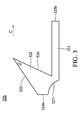
- FIG. 3 is a schematic view showing a lens in FIG. 2 ;
- FIG. 4 is a schematic view showing another embodiment of a backlight module of the invention.
- FIG. 5 is a schematic view showing a lens in FIG. 4 .
- a display 40 comprises a panel 41 and a backlight module 30 .
- the backlight module 30 comprises a reflective board 31 , a plurality of lenses 32 a , 32 b , 32 c , and 32 d , a shell 34 and a light source 33 .
- the reflective board 31 is installed in the shell 34 .
- Each lens 32 a , 32 b , 32 c , and 32 d comprises a bottom portion 321 and an extending portion 322 .
- the bottom portion 321 is parallel to and installed on the reflective board 31 .
- the extending portion 322 comprises reflective surface 323 located opposite to the reflective board 31 .
- the panel 41 is located opposite to the reflective board 31 .
- the backlight module 30 is installed between the panel 41 and the reflective board 31 .
- the lens 32 a connects to the lens 32 b
- the lens 32 c connects to the lens 32 d .
- the lenses 32 a , 32 b , 32 c , and 32 d respectively comprise first surfaces 324 a , 324 b , 324 c and 324 d .
- the first surface 324 a connects to the first surface 324 b
- the first surface 324 c connects to the first surface 324 d .
- the lenses 32 b and 32 c further comprise connecting surfaces 325 b and 325 c .
- the lens 32 b connects to the lens 32 c via connection of the connecting surfaces 325 b and 325 c.
- the lenses 32 a , 32 b , 32 c , and 32 d further respectively comprise a second surface 326 and an incident surface 327 .
- the light emitted from the light source 33 enters the lenses 32 a , 32 b , 32 c , and 32 d via the incident surface 327 and reaches the reflective surface 323 .
- the light is then reflected to strike the bottom portion 321 via the reflective surface 323 , and then passes through the bottom portion 321 to strike the reflective board 31 . Finally, the light is reflected to the panel 41 of the display 40 via the reflective board 31 .
- FIG. 3 shows the structure of the lens 32 b .
- the bottom portion 321 and the extending portion 322 extend in the same direction (as indicated by arrow C of FIG. 3 ).
- the second surface 326 is located between the reflective surface 323 and the bottom portion 321 .
- the incident surface 327 is located between the bottom portion 321 and the first surface 324 b .
- the first surface 324 b further connects to the reflective surface 323 . Note that the second surface 326 and the reflective surface 323 form an included angle ⁇ .
- the incident surface 327 is concave.
- FIG. 4 is a schematic view showing another embodiment of a backlight module 50 .
- a display 40 comprises a panel 41 and a backlight module 50 .
- the backlight module 50 comprises a reflective board 51 , a plurality of lenses 52 a , 52 b , 52 c , and 52 d , a shell 54 and a light source 53 .
- Each lens 52 a , 52 b , 52 c , and 52 d comprises a bottom portion 521 , an extending portion 522 and a refracting portion 528 .
- the bottom portion 521 is parallel to and installed on the reflective board 51 .
- the extending portion 522 comprises reflective surface 523 located opposite to the reflective board 51 .
- the refracting portion 528 is located between the bottom portion 521 and the extending portion 522 .
- the refracting portion 528 is curved.
- the panel 41 is located opposite to the reflective board 51 .
- the backlight module 50 is installed between the panel 41 and the reflective board 51 .
- the lens 52 a connects to the lens 52 b
- the lens 52 c connects to the lens 52 d .
- the structure of the lenses 52 a and 52 c and the structure of the lenses 52 b and 52 d are left-right reversed.
- the lenses 52 a , 52 b , 52 c , and 52 d respectively comprise first surfaces 524 a , 524 b , 524 c and 524 d .
- the first surface 524 a connects to the first surface 524 b
- the first surface 524 c connects to the first surface 524 d
- the lenses 52 b and 52 c further comprise connecting surfaces 525 b and 525 c .
- the lens 52 b connects to the lens 52 c via connection of the connecting surfaces 525 b and 525 c.
- the lenses 52 a , 52 b , 52 c , and 52 d further respectively comprise a second surface 526 and an incident surface 527 .
- the light emitted from the light source 53 enters the lenses 52 a , 52 b , 52 c , and 52 d via the incident surface 527 and reaches the reflective surface 523 .
- the light then passes through the refracting portion 528 and strikes the reflective surface 523 .
- the light is reflected to the bottom portion 521 via the reflective surface 523 , and then passes through the bottom portion 521 to strike the reflective board 51 . Finally, the light is reflected to the panel 41 of the display 40 via the reflective board 51 .
- FIG. 5 shows the structure of the lens 52 b .
- the bottom portion 521 and the extending portion 522 extend in the same direction (shown as arrow D of FIG. 5 ).
- the second surface 526 is located between the reflective surface 523 and the refracting portion 528 .
- the refracting portion 528 is adjacent to the bottom portion 521 .
- the incident surface 527 is located between the bottom portion 521 and the first surface 524 b .
- the first surface 524 b further connects to the reflective surface 523 . Note that the incident surface 527 is concave.
- the lenses 32 a , 32 b , 32 c , 32 d , 52 a , 52 b , 52 c , and 52 d and the backlight modules 30 and 50 of the display utilizing the lens can increase the distance of adjacent lenses. Moreover, the lenses 32 a , 32 b , 32 c , 32 d , 52 a , 52 b , 52 c , and 52 d and the backlight modules 30 and 50 can prevent increased backlight module thickness for averaging the lights. After the light strikes the reflective surfaces 323 and 523 and the reflective boards 31 and 51 , the light is directly reflected to the panel 41 .
- the backlight modules 30 and 50 utilizing the lenses 32 a , 32 b , 32 c , 32 d , 52 a , 52 b , 52 c , and 52 d not only increase the distance of adjacent lenses but also directly guides the light to the panel 41 .
Landscapes
- Physics & Mathematics (AREA)
- Nonlinear Science (AREA)
- Mathematical Physics (AREA)
- Chemical & Material Sciences (AREA)
- Crystallography & Structural Chemistry (AREA)
- General Physics & Mathematics (AREA)
- Optics & Photonics (AREA)
- Planar Illumination Modules (AREA)
Abstract
Description
Claims (15)
Applications Claiming Priority (3)
| Application Number | Priority Date | Filing Date | Title |
|---|---|---|---|
| TW95140968 | 2006-11-06 | ||
| TW095140968A TWI346820B (en) | 2006-11-06 | 2006-11-06 | Lens and backlight module of display utilizing the same |
| TW95140968A | 2006-11-06 |
Publications (2)
| Publication Number | Publication Date |
|---|---|
| US20080106902A1 US20080106902A1 (en) | 2008-05-08 |
| US8042965B2 true US8042965B2 (en) | 2011-10-25 |
Family
ID=39359556
Family Applications (1)
| Application Number | Title | Priority Date | Filing Date |
|---|---|---|---|
| US11/845,842 Active 2028-04-15 US8042965B2 (en) | 2006-11-06 | 2007-08-28 | Lens and backlight module of display utilizing the same |
Country Status (2)
| Country | Link |
|---|---|
| US (1) | US8042965B2 (en) |
| TW (1) | TWI346820B (en) |
Cited By (4)
| Publication number | Priority date | Publication date | Assignee | Title |
|---|---|---|---|---|
| US8864346B2 (en) * | 2012-12-10 | 2014-10-21 | GE Lighting Solutions, LLC | Lens-reflector combination for batwing light distribution |
| US9488864B2 (en) | 2014-06-28 | 2016-11-08 | Radiant Choice Limited | Light distributing optical component |
| US9568768B2 (en) | 2014-06-28 | 2017-02-14 | Radiant Choice Limited | Wavelength mixing optical component |
| US10558081B2 (en) * | 2016-06-08 | 2020-02-11 | Sakai Display Products Corporation | Light reflection device and light source device |
Families Citing this family (7)
| Publication number | Priority date | Publication date | Assignee | Title |
|---|---|---|---|---|
| WO2010146915A1 (en) * | 2009-06-15 | 2010-12-23 | シャープ株式会社 | Light-source unit, lighting device, displaying device, television-receiver device, and manufacturing method of reflection-sheets for light-sources |
| TWI408463B (en) * | 2010-11-18 | 2013-09-11 | Young Lighting Technology Corp | Light source module and illumination apparatus |
| CN103982855B (en) * | 2013-02-08 | 2017-01-11 | 香港理工大学 | lens and light-emitting device |
| CN104124239A (en) * | 2013-04-29 | 2014-10-29 | 展晶科技(深圳)有限公司 | Light emitting diode module |
| TWI536077B (en) * | 2014-04-09 | 2016-06-01 | 友達光電股份有限公司 | Optical assembly and back light module |
| KR102236711B1 (en) * | 2014-04-10 | 2021-04-06 | 엘지이노텍 주식회사 | Optical element and backlight unit including the same |
| JP6857739B2 (en) * | 2016-11-23 | 2021-04-14 | 深▲せん▼明智超精密科技有限公司Shenzhen Mingzhi Ultra Precision Technology Co.,Ltd. | Ultra-thin backlight lens |
Citations (3)
| Publication number | Priority date | Publication date | Assignee | Title |
|---|---|---|---|---|
| US20050001537A1 (en) * | 2003-03-28 | 2005-01-06 | Lumileds Lighting U.S., Llc | Multi-colored LED array with improved brightness profile and color uniformity |
| US6874900B2 (en) * | 2002-09-02 | 2005-04-05 | Hannstar Display Corp. | Panel light source device and liquid crystal display device |
| US20060067079A1 (en) * | 2004-09-25 | 2006-03-30 | Noh Ji-Whan | Side emitting device, backlight unit using the same as light source and liquid crystal display employing the backlight unit |
-
2006
- 2006-11-06 TW TW095140968A patent/TWI346820B/en active
-
2007
- 2007-08-28 US US11/845,842 patent/US8042965B2/en active Active
Patent Citations (3)
| Publication number | Priority date | Publication date | Assignee | Title |
|---|---|---|---|---|
| US6874900B2 (en) * | 2002-09-02 | 2005-04-05 | Hannstar Display Corp. | Panel light source device and liquid crystal display device |
| US20050001537A1 (en) * | 2003-03-28 | 2005-01-06 | Lumileds Lighting U.S., Llc | Multi-colored LED array with improved brightness profile and color uniformity |
| US20060067079A1 (en) * | 2004-09-25 | 2006-03-30 | Noh Ji-Whan | Side emitting device, backlight unit using the same as light source and liquid crystal display employing the backlight unit |
Cited By (4)
| Publication number | Priority date | Publication date | Assignee | Title |
|---|---|---|---|---|
| US8864346B2 (en) * | 2012-12-10 | 2014-10-21 | GE Lighting Solutions, LLC | Lens-reflector combination for batwing light distribution |
| US9488864B2 (en) | 2014-06-28 | 2016-11-08 | Radiant Choice Limited | Light distributing optical component |
| US9568768B2 (en) | 2014-06-28 | 2017-02-14 | Radiant Choice Limited | Wavelength mixing optical component |
| US10558081B2 (en) * | 2016-06-08 | 2020-02-11 | Sakai Display Products Corporation | Light reflection device and light source device |
Also Published As
| Publication number | Publication date |
|---|---|
| TWI346820B (en) | 2011-08-11 |
| TW200821699A (en) | 2008-05-16 |
| US20080106902A1 (en) | 2008-05-08 |
Similar Documents
| Publication | Publication Date | Title |
|---|---|---|
| US8042965B2 (en) | Lens and backlight module of display utilizing the same | |
| US7530723B2 (en) | Spread illuminating apparatus | |
| JP4262113B2 (en) | Backlight | |
| CN103869591B (en) | Display module and head-up display | |
| US20120314448A1 (en) | Vehicular Lamp | |
| US7614773B2 (en) | Light guide plate and liquid crystal display device having the same | |
| US20060104091A1 (en) | Light-conductive board and a rear light module using the light-conductive board | |
| US20170261179A1 (en) | Optical lens, backlight module and display device | |
| CN103244846A (en) | Light source module | |
| CN105556355A (en) | Light diffusing lens and light emitting device having same | |
| WO2011055795A1 (en) | Surface light source apparatus and display apparatus using same | |
| JP2009093808A (en) | Illumination device and liquid crystal display device | |
| US20100165662A1 (en) | Backlight unit | |
| US20140286000A1 (en) | Backlight unit and display device having the same | |
| US7573543B2 (en) | Light guide panel and display device employing the same | |
| KR101769971B1 (en) | Light guide plate and display device having the same | |
| CN102197256A (en) | Illuminating device, surface light source device, display device and television receiving device | |
| US20080074900A1 (en) | Backlight module | |
| US8436974B2 (en) | Illuminating device and liquid crystal display device provided with the same | |
| KR20150066847A (en) | Material for controlling luminous flux, light emitting device and display device | |
| US20110109835A1 (en) | Illumination device, surface light source device, and liquid crystal display device | |
| US11747543B1 (en) | Lighting system laminated into glasses using microLEDs and lens | |
| US11042061B2 (en) | Planar illumination device | |
| US20080151572A1 (en) | Light guide plate with light diffusing structure, backlight module and liquid crystal display using same | |
| US20080068860A1 (en) | Backlight module |
Legal Events
| Date | Code | Title | Description |
|---|---|---|---|
| AS | Assignment |
Owner name: AU OPTRONICS CORP., TAIWAN Free format text: ASSIGNMENT OF ASSIGNORS INTEREST;ASSIGNORS:PENG, CI-GUANG;CHOU, SHEN-HONG;REEL/FRAME:019753/0349;SIGNING DATES FROM 20070731 TO 20070822 Owner name: AU OPTRONICS CORP., TAIWAN Free format text: ASSIGNMENT OF ASSIGNORS INTEREST;ASSIGNORS:PENG, CI-GUANG;CHOU, SHEN-HONG;SIGNING DATES FROM 20070731 TO 20070822;REEL/FRAME:019753/0349 |
|
| STCF | Information on status: patent grant |
Free format text: PATENTED CASE |
|
| FPAY | Fee payment |
Year of fee payment: 4 |
|
| MAFP | Maintenance fee payment |
Free format text: PAYMENT OF MAINTENANCE FEE, 8TH YEAR, LARGE ENTITY (ORIGINAL EVENT CODE: M1552); ENTITY STATUS OF PATENT OWNER: LARGE ENTITY Year of fee payment: 8 |
|
| MAFP | Maintenance fee payment |
Free format text: PAYMENT OF MAINTENANCE FEE, 12TH YEAR, LARGE ENTITY (ORIGINAL EVENT CODE: M1553); ENTITY STATUS OF PATENT OWNER: LARGE ENTITY Year of fee payment: 12 |