US8042255B1 - Rapid fabrication techniques for arbitrary shape piezoelectric transducer sensors - Google Patents
Rapid fabrication techniques for arbitrary shape piezoelectric transducer sensors Download PDFInfo
- Publication number
- US8042255B1 US8042255B1 US12/287,164 US28716408A US8042255B1 US 8042255 B1 US8042255 B1 US 8042255B1 US 28716408 A US28716408 A US 28716408A US 8042255 B1 US8042255 B1 US 8042255B1
- Authority
- US
- United States
- Prior art keywords
- inner shell
- rigid inner
- conductive
- exterior surface
- location
- Prior art date
- Legal status (The legal status is an assumption and is not a legal conclusion. Google has not performed a legal analysis and makes no representation as to the accuracy of the status listed.)
- Expired - Fee Related, expires
Links
- 238000000034 method Methods 0.000 title claims abstract description 50
- 238000004519 manufacturing process Methods 0.000 title description 3
- 239000000463 material Substances 0.000 claims abstract description 50
- 230000000873 masking effect Effects 0.000 claims abstract description 29
- 239000004020 conductor Substances 0.000 claims abstract description 20
- 238000000576 coating method Methods 0.000 claims description 14
- 239000011248 coating agent Substances 0.000 claims description 13
- 238000000151 deposition Methods 0.000 claims description 11
- 239000007769 metal material Substances 0.000 claims description 7
- 238000004891 communication Methods 0.000 claims description 6
- RYGMFSIKBFXOCR-UHFFFAOYSA-N Copper Chemical compound [Cu] RYGMFSIKBFXOCR-UHFFFAOYSA-N 0.000 claims description 5
- 239000010949 copper Substances 0.000 claims description 5
- 229910052802 copper Inorganic materials 0.000 claims description 4
- 239000012809 cooling fluid Substances 0.000 claims description 3
- 239000011152 fibreglass Substances 0.000 claims description 3
- 239000011521 glass Substances 0.000 claims description 3
- 238000010438 heat treatment Methods 0.000 claims description 3
- 239000005060 rubber Substances 0.000 claims description 3
- 229910000831 Steel Inorganic materials 0.000 claims description 2
- 239000002131 composite material Substances 0.000 claims description 2
- 239000012530 fluid Substances 0.000 claims description 2
- 239000010959 steel Substances 0.000 claims description 2
- 239000000919 ceramic Substances 0.000 description 20
- 230000008569 process Effects 0.000 description 9
- 239000002184 metal Substances 0.000 description 5
- 229910052751 metal Inorganic materials 0.000 description 5
- 238000010285 flame spraying Methods 0.000 description 3
- 238000005507 spraying Methods 0.000 description 3
- 229910000881 Cu alloy Inorganic materials 0.000 description 2
- 229920001577 copolymer Polymers 0.000 description 2
- 230000008021 deposition Effects 0.000 description 2
- 238000005245 sintering Methods 0.000 description 2
- 239000006096 absorbing agent Substances 0.000 description 1
- 230000004888 barrier function Effects 0.000 description 1
- 229910010293 ceramic material Inorganic materials 0.000 description 1
- 230000008859 change Effects 0.000 description 1
- 238000002485 combustion reaction Methods 0.000 description 1
- 238000010276 construction Methods 0.000 description 1
- 238000001816 cooling Methods 0.000 description 1
- 239000000446 fuel Substances 0.000 description 1
- 238000009434 installation Methods 0.000 description 1
- 230000009972 noncorrosive effect Effects 0.000 description 1
- 230000008520 organization Effects 0.000 description 1
- 230000010355 oscillation Effects 0.000 description 1
- 229920006254 polymer film Polymers 0.000 description 1
- 229920001296 polysiloxane Polymers 0.000 description 1
- 229910000679 solder Inorganic materials 0.000 description 1
- 239000007787 solid Substances 0.000 description 1
- 239000002904 solvent Substances 0.000 description 1
- 238000004544 sputter deposition Methods 0.000 description 1
- 239000010935 stainless steel Substances 0.000 description 1
- 229910001220 stainless steel Inorganic materials 0.000 description 1
- XLYOFNOQVPJJNP-UHFFFAOYSA-N water Substances O XLYOFNOQVPJJNP-UHFFFAOYSA-N 0.000 description 1
Images

Classifications
-
- H—ELECTRICITY
- H04—ELECTRIC COMMUNICATION TECHNIQUE
- H04R—LOUDSPEAKERS, MICROPHONES, GRAMOPHONE PICK-UPS OR LIKE ACOUSTIC ELECTROMECHANICAL TRANSDUCERS; DEAF-AID SETS; PUBLIC ADDRESS SYSTEMS
- H04R17/00—Piezoelectric transducers; Electrostrictive transducers
- H04R17/005—Piezoelectric transducers; Electrostrictive transducers using a piezoelectric polymer
-
- H—ELECTRICITY
- H04—ELECTRIC COMMUNICATION TECHNIQUE
- H04R—LOUDSPEAKERS, MICROPHONES, GRAMOPHONE PICK-UPS OR LIKE ACOUSTIC ELECTROMECHANICAL TRANSDUCERS; DEAF-AID SETS; PUBLIC ADDRESS SYSTEMS
- H04R31/00—Apparatus or processes specially adapted for the manufacture of transducers or diaphragms therefor
-
- H—ELECTRICITY
- H04—ELECTRIC COMMUNICATION TECHNIQUE
- H04R—LOUDSPEAKERS, MICROPHONES, GRAMOPHONE PICK-UPS OR LIKE ACOUSTIC ELECTROMECHANICAL TRANSDUCERS; DEAF-AID SETS; PUBLIC ADDRESS SYSTEMS
- H04R1/00—Details of transducers, loudspeakers or microphones
- H04R1/44—Special adaptations for subaqueous use, e.g. for hydrophone
-
- Y—GENERAL TAGGING OF NEW TECHNOLOGICAL DEVELOPMENTS; GENERAL TAGGING OF CROSS-SECTIONAL TECHNOLOGIES SPANNING OVER SEVERAL SECTIONS OF THE IPC; TECHNICAL SUBJECTS COVERED BY FORMER USPC CROSS-REFERENCE ART COLLECTIONS [XRACs] AND DIGESTS
- Y10—TECHNICAL SUBJECTS COVERED BY FORMER USPC
- Y10T—TECHNICAL SUBJECTS COVERED BY FORMER US CLASSIFICATION
- Y10T29/00—Metal working
- Y10T29/42—Piezoelectric device making
-
- Y—GENERAL TAGGING OF NEW TECHNOLOGICAL DEVELOPMENTS; GENERAL TAGGING OF CROSS-SECTIONAL TECHNOLOGIES SPANNING OVER SEVERAL SECTIONS OF THE IPC; TECHNICAL SUBJECTS COVERED BY FORMER USPC CROSS-REFERENCE ART COLLECTIONS [XRACs] AND DIGESTS
- Y10—TECHNICAL SUBJECTS COVERED BY FORMER USPC
- Y10T—TECHNICAL SUBJECTS COVERED BY FORMER US CLASSIFICATION
- Y10T29/00—Metal working
- Y10T29/49—Method of mechanical manufacture
- Y10T29/49002—Electrical device making
- Y10T29/49005—Acoustic transducer
-
- Y—GENERAL TAGGING OF NEW TECHNOLOGICAL DEVELOPMENTS; GENERAL TAGGING OF CROSS-SECTIONAL TECHNOLOGIES SPANNING OVER SEVERAL SECTIONS OF THE IPC; TECHNICAL SUBJECTS COVERED BY FORMER USPC CROSS-REFERENCE ART COLLECTIONS [XRACs] AND DIGESTS
- Y10—TECHNICAL SUBJECTS COVERED BY FORMER USPC
- Y10T—TECHNICAL SUBJECTS COVERED BY FORMER US CLASSIFICATION
- Y10T29/00—Metal working
- Y10T29/49—Method of mechanical manufacture
- Y10T29/49002—Electrical device making
- Y10T29/49007—Indicating transducer
-
- Y—GENERAL TAGGING OF NEW TECHNOLOGICAL DEVELOPMENTS; GENERAL TAGGING OF CROSS-SECTIONAL TECHNOLOGIES SPANNING OVER SEVERAL SECTIONS OF THE IPC; TECHNICAL SUBJECTS COVERED BY FORMER USPC CROSS-REFERENCE ART COLLECTIONS [XRACs] AND DIGESTS
- Y10—TECHNICAL SUBJECTS COVERED BY FORMER USPC
- Y10T—TECHNICAL SUBJECTS COVERED BY FORMER US CLASSIFICATION
- Y10T29/00—Metal working
- Y10T29/49—Method of mechanical manufacture
- Y10T29/49002—Electrical device making
- Y10T29/4902—Electromagnet, transformer or inductor
- Y10T29/4908—Acoustic transducer
Definitions
- the present invention relates generally to methods for rapidly making piezoelectric transducers using piezoelectric material.
- the invention is directed to a method for building a transducer onto an inner form with a conductive surface.
- piezoelectric transducers have been produced using flat sheets of material that are cut into segments and adhesively bonded to a desired configuration.
- U.S. Pat. No. 4,787,126 issued Nov. 29, 1988, to Oliver, discloses a dark field ultrasonic transducer that is constructed with an outer annular spherical or conical transducer element and an inner spherical element.
- the outer annular element is excited and insonifies a small portion of a part surface near a discontinuity or crack with longitudinal waves or with surface waves.
- the inner dark field element is not focused to be sensitive to either reflected sound or waves reradiated from the surface waves, but detects sound scattered from surface discontinuities such as a crack edge.
- surface waves strike a crack edge and restrikes it after reflection from the bottom of the crack, two pulses are received and the time delay between them is a measure of crack depth.
- the crack shape and crack depth profile are determined as the part is scanned.
- a sphere-cone transducer the preferred embodiment, is fabricated by stretching thin piezoelectric polymer film over a tool having a ball embedded in a conical surface.
- U.S. Pat. No. 5,825,902 issued Oct. 20, 1998, to Fujishima, discloses a spherical piezoelectric speaker having a small and simple structure, a wide sound frequency range and a high sound pressure includes a spherical shell piezoelectric ceramic body which is hollow inside and an external electrode and an internal electrode defining a driving device for oscillating the spherical shell piezoelectric ceramic body.
- a sound absorber is provided in a hollow section of the piezoelectric ceramic body and a frame for holding the piezoelectric ceramic body is disposed on the outer surface of the piezoelectric ceramic body via dampers for reducing an influence of external oscillation.
- Conductive electrodes are positioned on opposed surfaces of said sphere and conductors enable application of an electrical potential between the conductive electrodes to enable a field to be applied to the sphere that causes a dimension change in the radius aspect and thickness aspect thereof.
- U.S. Pat. No. 6,654,993, issued Dec. 2, 2003, to Zhang et al discloses a process for fabricating a ceramic electroactive transducer of a predetermined shape.
- the process comprises the steps of providing a suitably shaped core having an outer surface, attaching a first conductor to the outer surface of the core, coating an inner conductive electrode on the outer surface of the core such that the inner conductive electrode is in electrical communication with the first conductor, coating a ceramic layer onto the inner electrode, thereafter sintering the ceramic layer, coating an outer electrode onto the sintered ceramic layer to produce an outer electrode that is not in electrical communication with the first conductor, and then poling the sintered ceramic layer across the inner electrode and the outer electrode to produce the ceramic electrode.
- U.S. Pat. No. 7,019,445, issued Mar. 28, 2006, to Zhang et al discloses a′process for fabricating a ceramic electroactive transducer of a predetermined shape.
- the process comprises the steps of providing a suitably shaped core having an outer surface, attaching a first conductor to the outer surface of the core, coating an inner conductive electrode on the outer surface of the core such that the inner conductive electrode is in electrical communication with the first conductor, coating a ceramic layer onto the inner electrode, thereafter sintering the ceramic layer, coating an outer electrode onto the sintered ceramic layer to produce an outer electrode that is not in electrical communication with the first conductor, and then poling the sintered ceramic layer across the inner electrode and the outer electrode to produce the ceramic electrode.
- the inner metallic coating used by Zhang is simply a metallic coating that is not sufficiently thick to be strong enough to provide support. Instead, Zhang utilizes ceramic as the structural material. Use in underwater environments where pressure is encountered is likely to be problematic and may crush, crack or deform the ceramic material of the Zhang transducer.
- An object of the present invention is to provide an improved acoustic transducer.
- Another object of the present invention is to provide a more rapid method for making acoustic transducers.
- steps may comprise providing a rigid inner shell with a conductive exterior surface and applying masking material onto a first location on the conductive exterior surface of the rigid inner shell.
- steps may comprise depositing piezoelectric material over the conductive exterior surface of the rigid inner shell and the masking material.
- steps may also comprise depositing conductive material onto the piezoelectric material.
- the method may comprise removing the masking material from the first location on the conductive exterior surface of the rigid inner shell.
- the method may comprise attaching a first signal lead to the first location on the conductive exterior surface of the rigid inner shell and/or attaching a second signal lead to the conductive material.
- the method may comprise providing that the rigid inner shell is hollow prior to the step of depositing piezoelectric material over the conductive exterior surface of the rigid inner shell and the masking material.
- the method may comprise applying the masking material onto a second location on the conductive exterior surface of the rigid inner shell, removing the masking material from the second location, and/or forming a port at the second location wherein the port leads to an interior of the rigid inner shell.
- the method may comprise providing that the inner shell is sufficiently strong for use in an underwater environment.
- the method may comprise forming at least one port in communication with an interior of the inner shell.
- the method may further comprise introducing at least one of heating fluid or cooling fluid through at least one port.
- the method may comprise forming threads within at least one port.
- the method may comprise utilizing the threads as a mounting to hold the inner shell during the making of the transducer.
- the method may comprise utilizing a port for pressure balancing of the acoustic transducer for use underwater.
- the method may comprise applying an electrically insulating and moisture resistant coating over the conductive material.
- the method may comprise forming the rigid inner shell from a metallic material.
- the metallic material might comprise copper greater than 0.0005 inches in thickness.
- the metallic material might comprise steel or other metallic material greater than 0.0005 inches in thickness.
- the method may comprise forming the rigid inner shell from at least one of fiberglass, rubber, glass, or composite material, which may be coated with conductive material.
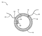
- the FIGURE is an elevational view, in cross-section, showing a piezoelectric acoustic sensor in accord with one possible embodiment of the present invention.
- the present invention may be utilized for rapidly fabricating piezoelectric acoustic sensors. Not only are the acoustic sensors rapidly produced, they are far superior to sensors constructed by cut and bond methods whereby flat sheets of material are cut into segments and adhesively bonded to a desired configuration, as discussed hereinbefore.
- transducer 10 that may be rapidly produced using a fabrication technique in accord with one possible embodiment of the present invention.
- transducer 10 is spherical.
- other shapes for the transducers may include but are not limited to cylinders, cubes, rectangles, and the like.
- the method of the present invention may produce a transducer of any shape into which inner shell 12 may be formed.
- Inner shell 12 can be any rigid material as dictated by structural considerations. Inner shell 12 may be hollow as indicated and as further discussed below with various advantages for this construction. Structural considerations might include, for instance, operating in underwater environments wherein significant pressure and/or water currents may be found. Copper or copper alloy comprises one possible preferred rigid material because of its electrical conductivity. In one possible embodiment, the copper material thickness of inner shell 12 might be greater than 0.001 inches or 0.0005 inches. (Note that the FIGURE is not intended to be representative of actual dimensions.) In another embodiment, stainless steel greater than 0.001 inches or 0.0005 inches could also be used but may need copper coating. Metallic coatings may often be less than 0.0005 inches, may be better measured in microns, and may be less than 100 microns. However, the invention is not limited to the above dimensions.
- a suitable rigid material such as fiberglass, rubber or glass may be used to form a portion of inner shell 12 .
- Non-conductive rigid materials may be utilized as long as the material may be coated with metal to provide a conductive outer surface. While, the material for the internal spherical shell is not necessarily critical, the material should be sufficiently strong to resist forces of the environment in which transducer 10 operates.
- a spot or masking region, such as spot or masking region 14 , on an outside surface of inner shell 12 may be selected and covered with a masking material.
- Masking can be performed at room temperature utilizing vulcanizing silicone as the masking material. However, other masking materials such as non-corrosive masking materials may be used. The masking material may be removed later in the process as discussed hereinafter.
- Piezoelectric layer 16 of piezoelectric material such as piezoelectric copolymer, VF2-TrFE, may be flame sprayed over the entire outer surface of inner shell 12 .
- Piezoelectric layer 16 can be deposited by any process that allows control over the thickness of the material. Thickness is typically important for properly optimizing the transducer.
- Known spraying processes having these characteristics include flame spraying and ordinary spraying. In flame spraying, combustion of a gaseous fuel may be used to carry the copolymer piezoelectric material to the shell. In the ordinary spraying process, the piezoelectric material may be mixed with a solvent and sprayed on the shell.
- Outer metal layer 18 can then be deposited over the piezoelectric layer 16 .
- Outer metal layer 18 can be applied by flame spraying or sputtering. The primary reason for outer metal layer 18 is to provide a contact on the outer surface of transducer 10 . If required, cooling fluid could be circulated through port 28 to control temperature within transducer 10 during these processes.
- the masking material and the material deposited onto spot or masking region 14 may then be removed, exposing the metal surface of the inner shell 12 .
- Signal leads 20 and 24 may be secured to spot or masking region 14 and to spot or region 22 .
- region 22 may comprise solder or other means for attaching wire 24 .
- contact poling leads and/or signal leads 20 and 24 might be utilized to apply a voltage to polarize the piezoelectric layer 16 .
- a conformal coating may be applied over the outside of transducer 10 to provide an electrically insulating and moisture resistant barrier.
- a portion of inner shell 12 might be, masked before deposition of piezoelectric layer 16 . If additional ports are desired, corresponding regions may also be masked. The masking prevents deposition of piezoelectric layer 16 at the port region wherein port 28 is formed. Other means to form at least one port 28 might also be utilized.
- port 28 may serve many uses. Port 28 may be used to hold inner shell 12 while the layers are applied. Heating and cooling may be accomplished through port 28 or multiple ports 28 , if required. If inner shell 12 is solid, a tapped hole with threads 26 can be used to provide a holding and mounting point for fabrication and installation. When transducer 10 is hollow and used under pressure circumstances, port 28 may be used to pressure compensate (balance) transducer 12 .
- steps might comprise providing a rigid inner shell with a conductive exterior surface and applying masking material onto a first location on the conductive exterior surface of the rigid inner shell.
- steps may comprise depositing piezoelectric material over the conductive exterior surface of the rigid inner shell and the masking material.
- steps may also comprise depositing conductive material onto the piezoelectric material.
- the method may comprise removing the masking material from the first location on the conductive exterior surface of the rigid inner shell.
- the method may comprise attaching a first signal lead to the first location on the conductive exterior surface of the rigid inner shell and/or attaching a second signal lead to the conductive material.
Landscapes
- Engineering & Computer Science (AREA)
- Physics & Mathematics (AREA)
- Acoustics & Sound (AREA)
- Signal Processing (AREA)
- Manufacturing & Machinery (AREA)
- Transducers For Ultrasonic Waves (AREA)
Abstract
Description
Claims (14)
Priority Applications (1)
| Application Number | Priority Date | Filing Date | Title |
|---|---|---|---|
| US12/287,164 US8042255B1 (en) | 2008-09-30 | 2008-09-30 | Rapid fabrication techniques for arbitrary shape piezoelectric transducer sensors |
Applications Claiming Priority (1)
| Application Number | Priority Date | Filing Date | Title |
|---|---|---|---|
| US12/287,164 US8042255B1 (en) | 2008-09-30 | 2008-09-30 | Rapid fabrication techniques for arbitrary shape piezoelectric transducer sensors |
Publications (1)
| Publication Number | Publication Date |
|---|---|
| US8042255B1 true US8042255B1 (en) | 2011-10-25 |
Family
ID=44801303
Family Applications (1)
| Application Number | Title | Priority Date | Filing Date |
|---|---|---|---|
| US12/287,164 Expired - Fee Related US8042255B1 (en) | 2008-09-30 | 2008-09-30 | Rapid fabrication techniques for arbitrary shape piezoelectric transducer sensors |
Country Status (1)
| Country | Link |
|---|---|
| US (1) | US8042255B1 (en) |
Citations (2)
| Publication number | Priority date | Publication date | Assignee | Title |
|---|---|---|---|---|
| US5825902A (en) * | 1995-10-06 | 1998-10-20 | Murata Manufacturing Co., Ltd. | Spherical piezoelectric speaker |
| US6060818A (en) * | 1998-06-02 | 2000-05-09 | Hewlett-Packard Company | SBAR structures and method of fabrication of SBAR.FBAR film processing techniques for the manufacturing of SBAR/BAR filters |
-
2008
- 2008-09-30 US US12/287,164 patent/US8042255B1/en not_active Expired - Fee Related
Patent Citations (2)
| Publication number | Priority date | Publication date | Assignee | Title |
|---|---|---|---|---|
| US5825902A (en) * | 1995-10-06 | 1998-10-20 | Murata Manufacturing Co., Ltd. | Spherical piezoelectric speaker |
| US6060818A (en) * | 1998-06-02 | 2000-05-09 | Hewlett-Packard Company | SBAR structures and method of fabrication of SBAR.FBAR film processing techniques for the manufacturing of SBAR/BAR filters |
Similar Documents
| Publication | Publication Date | Title |
|---|---|---|
| Kobayashi et al. | Piezoelectric thick bismuth titanate/lead zirconate titanate composite film transducers for smart NDE of metals | |
| US6215231B1 (en) | Hollow sphere transducers | |
| US20110026367A1 (en) | Acoustic Transducer | |
| CA2105647C (en) | Air coupled ultrasonic transducer | |
| JP6552644B2 (en) | Impedance matching layer for ultrasonic transducers with metallic protective structure | |
| JP4446000B2 (en) | Diaphragm pot for ultrasonic converter | |
| Salowitz et al. | Microfabricated expandable sensor networks for intelligent sensing materials | |
| US4469976A (en) | Single-side connected transducer | |
| US10564132B2 (en) | Method for fabricating a layered structure using surface micromachining | |
| US20110062535A1 (en) | Mems transducers | |
| CN105657626A (en) | Capacitive micromachined ultrasonic transducer and test object information acquiring apparatus including the same | |
| Ning et al. | Fabrication of a silicon micromachined capacitive microphone using a dry-etch process | |
| US20080127727A1 (en) | Piezoelectric Sensor Comprising a Thermal Sensor and an Amplifier Circuit | |
| US8042255B1 (en) | Rapid fabrication techniques for arbitrary shape piezoelectric transducer sensors | |
| Meyer et al. | Design of and fabrication improvements to the cymbal transducer aided by finite element analysis | |
| CN110301002B (en) | Diaphragm pot for an ultrasonic transducer, method for producing a diaphragm pot, and ultrasonic transducer | |
| US5724315A (en) | Omnidirectional ultrasonic microprobe hydrophone | |
| JPH06101879B2 (en) | Aerial ultrasonic transducer | |
| KR100671419B1 (en) | Acoustic Impedance Matching Layer for High Frequency Ultrasonic Transducer and Method for Fabricating Ultrasonic Transducer by using it | |
| JP3313171B2 (en) | Ultrasonic probe and manufacturing method thereof | |
| JP4630988B2 (en) | Piezoelectric fiber and nondestructive inspection method using the same | |
| US20070230275A1 (en) | Method for manufacturing an ultrasound test head with an ultrasonic transducer configuration with a curved send and receive surface | |
| US6561034B2 (en) | Ultrasonic sparse imaging array | |
| KR102432777B1 (en) | Ultrasonic sensor and method of manufacturing the same | |
| US10197689B1 (en) | Physically damped noise canceling hydrophone |
Legal Events
| Date | Code | Title | Description |
|---|---|---|---|
| AS | Assignment |
Owner name: UNITED STATES OF AMERICA, THE, RHODE ISLAND Free format text: ASSIGNMENT OF ASSIGNORS INTEREST;ASSIGNOR:JEVNAGER, MICHAEL D.;REEL/FRAME:021879/0910 Effective date: 20080930 |
|
| ZAAA | Notice of allowance and fees due |
Free format text: ORIGINAL CODE: NOA |
|
| ZAAB | Notice of allowance mailed |
Free format text: ORIGINAL CODE: MN/=. |
|
| STCF | Information on status: patent grant |
Free format text: PATENTED CASE |
|
| REMI | Maintenance fee reminder mailed | ||
| FPAY | Fee payment |
Year of fee payment: 4 |
|
| SULP | Surcharge for late payment | ||
| MAFP | Maintenance fee payment |
Free format text: PAYMENT OF MAINTENANCE FEE, 8TH YEAR, LARGE ENTITY (ORIGINAL EVENT CODE: M1552); ENTITY STATUS OF PATENT OWNER: LARGE ENTITY Year of fee payment: 8 |
|
| FEPP | Fee payment procedure |
Free format text: MAINTENANCE FEE REMINDER MAILED (ORIGINAL EVENT CODE: REM.); ENTITY STATUS OF PATENT OWNER: LARGE ENTITY |
|
| LAPS | Lapse for failure to pay maintenance fees |
Free format text: PATENT EXPIRED FOR FAILURE TO PAY MAINTENANCE FEES (ORIGINAL EVENT CODE: EXP.); ENTITY STATUS OF PATENT OWNER: LARGE ENTITY |
|
| STCH | Information on status: patent discontinuation |
Free format text: PATENT EXPIRED DUE TO NONPAYMENT OF MAINTENANCE FEES UNDER 37 CFR 1.362 |
|
| FP | Lapsed due to failure to pay maintenance fee |
Effective date: 20231025 |