US8038476B2 - Network connector - Google Patents
Network connector Download PDFInfo
- Publication number
- US8038476B2 US8038476B2 US12/871,398 US87139810A US8038476B2 US 8038476 B2 US8038476 B2 US 8038476B2 US 87139810 A US87139810 A US 87139810A US 8038476 B2 US8038476 B2 US 8038476B2
- Authority
- US
- United States
- Prior art keywords
- circuit board
- insulative
- input circuit
- output circuit
- insulative housing
- Prior art date
- Legal status (The legal status is an assumption and is not a legal conclusion. Google has not performed a legal analysis and makes no representation as to the accuracy of the status listed.)
- Expired - Fee Related
Links
Images


Classifications
-
- H—ELECTRICITY
- H01—ELECTRIC ELEMENTS
- H01R—ELECTRICALLY-CONDUCTIVE CONNECTIONS; STRUCTURAL ASSOCIATIONS OF A PLURALITY OF MUTUALLY-INSULATED ELECTRICAL CONNECTING ELEMENTS; COUPLING DEVICES; CURRENT COLLECTORS
- H01R13/00—Details of coupling devices of the kinds covered by groups H01R12/70 or H01R24/00 - H01R33/00
- H01R13/66—Structural association with built-in electrical component
- H01R13/665—Structural association with built-in electrical component with built-in electronic circuit
- H01R13/6658—Structural association with built-in electrical component with built-in electronic circuit on printed circuit board
-
- H—ELECTRICITY
- H01—ELECTRIC ELEMENTS
- H01R—ELECTRICALLY-CONDUCTIVE CONNECTIONS; STRUCTURAL ASSOCIATIONS OF A PLURALITY OF MUTUALLY-INSULATED ELECTRICAL CONNECTING ELEMENTS; COUPLING DEVICES; CURRENT COLLECTORS
- H01R13/00—Details of coupling devices of the kinds covered by groups H01R12/70 or H01R24/00 - H01R33/00
- H01R13/66—Structural association with built-in electrical component
- H01R13/719—Structural association with built-in electrical component specially adapted for high frequency, e.g. with filters
-
- H—ELECTRICITY
- H01—ELECTRIC ELEMENTS
- H01R—ELECTRICALLY-CONDUCTIVE CONNECTIONS; STRUCTURAL ASSOCIATIONS OF A PLURALITY OF MUTUALLY-INSULATED ELECTRICAL CONNECTING ELEMENTS; COUPLING DEVICES; CURRENT COLLECTORS
- H01R2107/00—Four or more poles
Definitions
- a network connector may produce high frequency waves to interfere with surrounding electronic devices. Further, the transmitting signal in a network connector may be interfered with noises produced by the external transmission line.
- a network connector may have a metal shield surrounded on the outside for protection against external electromagnetic waves and a filter module installed therein to eliminate internal noises, maintaining the quality of the signal being transmitted to the host for data processing.
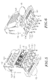
- FIGS. 7 and 8 illustrate a network connector according to the prior art.
- the network connector comprises a base block A, two sets of terminals A 1 ; A 4 arranged on left and right sides of the base block A, an accommodation space A 0 defined in the base block A between the terminals A 1 ; A 4 , a plurality of filter members B accommodated in the accommodation space A 0 , a circuit board A 2 attached to the accommodation space A 0 and having metal contacts A 21 respectively bonded with the terminals A 1 , an electrically insulative housing A 3 attached to the base block A, a back panel A 31 attached to the rear side of the electrically insulative housing A 3 , a plurality of LEDs A 32 mounted in the electrically insulative housing A 3 and having lead-out wires A 321 inserted through the back panel A 31 to the outside, and a metal shield C surrounding the electrically insulative housing A 3 , the base block A and the back panel A 31 .
- the metal shield C defines an insertion hole C 1 for insertion of an external electrical connector (electrical plug).
- the filter members B include one filter capacitor B 2 and a plurality of filter coils B 1 .
- the filter capacitor B 2 has two end pins B 21 respectively extended from the two opposite ends thereof.
- One end pin B 21 is bonded to the metal contacts A 21 of the circuit board A 2 .
- the other end pin B 21 is extended through the back panel A 31 to the outside and connected to the metal shield C.
- the filter coils B 1 of the filter members B are respectively wound round head ends A 11 of the terminals A 1 .
- the terminals A 1 that are arranged on the left side of the base block A are positioned in the insertion hole C 1 for the contact of the terminals of the inserted external electrical connector (electrical plug).
- the assembly process of the aforesaid prior art network connector is complicated. During connection between the filter coils B 1 and the terminals A 1 , the filter coils B 1 must be respectively wound round the head ends A 11 of the terminals A 1 , wasting much time and labor. Further, after bonding of the end pin B 21 of the filter capacitor B 2 and a plurality of filter coils B 1 to the metal contacts A 21 of the circuit board A 2 , no any isolation means is set between the end pin B 21 of the filter capacitor B 2 and the terminals A 4 . When the network connector receives an external high voltage, electrical sparks may be produced between the end pin B 21 of the filter capacitor B 2 and the terminals A 4 .
- the end pin B 21 of the filter capacitor B 2 and the lead-out wires A 321 of the LEDs A 32 are not well shielded and isolated, and electrical sparks may be produced between the end pin B 21 of the filter capacitor B 2 and the lead-out wires A 321 of the LEDs A 32 accidentally. Therefore, the aforesaid prior art network connector has the drawbacks of complicated structure, high manufacturing cost and low voltage withstand strength.
- the present invention has been accomplished under the circumstances in view. It is one object of the present invention to provide a network connector, which has the lead wires of filter coils of a filter module thereof respectively bonded to respective surface contacts at an input circuit board and an output circuit board by surface mount technology, simplifying the manufacturing process, lowering the manufacturing cost and enhancing the electrical characteristics.
- FIG. 1 is an oblique elevation of a network connector in accordance with the present invention.
- FIG. 2 is an exploded view of the network connector in accordance with the present invention.
- FIG. 3 is another exploded view of the network connector in accordance with the present invention when viewed from another angle.
- FIG. 4 is a sectional side view of the network connector in accordance with the present invention.
- FIG. 5 is an elevational assembly view of a part of the network connector in accordance with the present invention.
- FIG. 6 corresponds to FIG. 5 when viewed from another angle.
- FIG. 7 is an exploded view of a network connector according to the prior art.
- FIG. 8 is a sectional side view of the network connector according to the prior art.
- a network connector in accordance with the present invention comprising an electrically insulative housing 1 having an insertion hole 11 on its one side, i.e., the front side, an output circuit board 12 and an input circuit board 13 mounted in the electrically insulative housing 1 , a plurality of output terminals 111 mounted in the insertion hole 11 of the electrically insulative housing 1 and electrically connected to the output circuit board 12 , a plurality of input terminals 112 electrically connected to the input circuit board 13 and extending out of the opposite side, namely, the bottom side of the electrically insulative housing 1 , and a filter module 2 that comprises a plurality of filter coils 21 bonded to surface contacts 121 at the output circuit board 12 and surface contacts 131 at the input circuit board 13 by surface mount technology.
- the electrically insulative housing 1 has mounted therein LEDs 14 , a filter capacitor 15 , an electrically insulative partition block 16 and an electrically insulative holder panel 17 .
- the electrically insulative housing 1 further has a mounting chamber 10 in the bottom side thereof.
- the insertion hole 11 of the electrically insulative housing 1 is configured to receive an external RJ-45 male connector. When an external RJ-45 male connector is inserted into the insertion hole 11 of the electrically insulative housing 1 , the inserted RJ-45 male connector is electrically kept in contact with the output terminals 111 . Further, the electrically insulative partition block 16 and the electrically insulative holder panel 17 are properly mounted in the mounting chamber 10 of the electrically insulative housing 1 .
- the filter coils 21 of the filter module 2 each have opposing lead wires 211 respectively bonded to the surface contacts 121 of the output circuit board 12 and the surface contacts 131 of the input circuit board 13 by surface mount technology.
- the assembly of the filter module 2 , output circuit board 12 and input circuit board 13 is mounted in the electrically insulative partition block 16 , and then bonding ends 1111 of the output terminals 111 are inserted through the electrically insulative partition block 16 into respective via holes 122 of the output circuit board 12 and bonded thereto.
- the input circuit board 13 is fastened to a locating groove 161 at the back side of the electrically insulative partition block 16 , and kept perpendicular to the input circuit board 13 .
- the input circuit board 13 has an extension portion 132 inserted through a slot 162 of the electrically insulative partition block 16 .
- the filter capacitor 15 is mounted in a locating hole 163 of the electrically insulative partition block 16 , having two pins 151 respectively extended from its two opposite ends.
- One pin 151 of the filter capacitor 15 is inserted through a through hole 164 of the electrically insulative partition block 16 and bonded to a via hole 123 of the output circuit board 12 .
- the other pin 151 of the filter capacitor 15 is inserted through a through hole 133 and bonded to a via hole 133 on the extension portion 132 of the input circuit board 13 .
- the input terminals 112 each have a bonding end 1121 respectively bonded to a respective contact 134 at the back side of the input circuit board 13 by hot press soldering.
- the assembly of the filter module 2 , output circuit board 12 , input circuit board 13 , output terminals 111 , input terminals 112 and electrically insulative partition block 16 are properly mounted in the mounting chamber 10 of the electrically insulative housing 1 , and then the LEDs 14 are mounted in the electrically insulative housing 1 , and then the electrically insulative holder panel 17 is attached to the bottom side of the electrically insulative housing 1 to force multiple retaining blocks 171 at the two opposite lateral sides thereof into engagement with respective retaining holes 101 in the electrically insulative housing 1 , thereby closing the mounting chamber 10 .
- the electrically insulative holder panel 17 lifts the assembly of the filter module 2 , output circuit board 12 , input circuit board 13 , output terminals 111 , input terminals 112 and electrically insulative partition block 16 in the mounting chamber 10 of the electrically insulative housing 1 .
- a metal shield 3 is mounted around the electrically insulative housing 1 , finishing the assembly process of the network connector.
- the bonding ends 1121 of the input terminals 112 are isolated, avoiding accidental electrical sparks between the bonding ends 1121 of the input terminals 112 and the pins 151 of the filter capacitor 15 , and enhancing the network's voltage withstand strength.
- the lead wires 211 of the filter coils 21 of the filter module 2 are respectively bonded to the surface contacts 121 of the output circuit board 12 and the surface contacts 131 of the input circuit board 13 by surface mount technology but not wound round the output terminals 111 and the input terminals 112 .
- the installation of the filter coils 21 of the filter module 2 is simplified to lower the manufacturing cost. Further, this filter module installation design also enhances the electrical characteristics during signal transmission.
- the scope of the present invention is to directly bond the lead wires 211 of the filter coils 21 of the filter module 2 to the surface contacts 121 of the output circuit board 12 and the surface contacts 131 of the input circuit board 13 by surface mount technology, minimizing contact points in the network connector and avoiding signal attenuation during signal transmission.
- the installation of the filter coils 21 of the filter module 2 is simplified, lowering the manufacturing cost and enhancing electrical characteristics during signal transmission.
Landscapes
- Engineering & Computer Science (AREA)
- Microelectronics & Electronic Packaging (AREA)
- Details Of Connecting Devices For Male And Female Coupling (AREA)
Abstract
A network connector includes an electrically insulative housing accommodating an output circuit board and an input circuit board, output terminals and input terminals respectively and electrically bonded to the output circuit board and the input circuit board, a filter capacitor electrically connected between the input circuit board and the output circuit board, an electrically insulative partition block mounted in the electrically insulative housing to keep the filter capacitor away from the input circuit board and the output circuit board and to avoid accidental electrical sparks between the input terminals and the filter capacitor, and a filter module having filter coils electrically bonded to the surface contacts at the output circuit board and the input circuit board by surface mount technology.
Description
This application claims the priority benefit of Taiwan patent application number 098218319, filed on Oct. 5, 2010.
1. Field of the Invention
The present invention relates to network technology and more particularly, to a network connector, which has the lead wires of filter coils of a filter module thereof respectively bonded to respective surface contacts at an input circuit board and an output circuit board by surface mount technology, minimizing contact points, simplifying the manufacturing process, lowering the manufacturing cost and enhancing the electrical characteristics.
2. Description of the Related Art
Nowadays, following fast development of computer technology, computer data transmission speed has been greatly improved. Moreover, as network communication technologies develop rapidly and vigorously, it is possible for the people to transmit data, to hold a video conference, to book tickets, to play on-line games, and to inquire information and different application procedures through the internet. Nowadays, many people use the internet to achieve different works. In consequence, many kinds of network connectors have been created as communication means between a computer and an external network. Regular network connectors, for example, RJ-45 connectors, are commonly used for digital communication. During the use of a network connector, the problem of signal interference due to electromagnetic effect must be taken into account. The interference of noises may come from two sources, i.e., the interference of surrounding electromagnetic waves and the interference of internal noises. A network connector may produce high frequency waves to interfere with surrounding electronic devices. Further, the transmitting signal in a network connector may be interfered with noises produced by the external transmission line. In order to eliminate interference, a network connector may have a metal shield surrounded on the outside for protection against external electromagnetic waves and a filter module installed therein to eliminate internal noises, maintaining the quality of the signal being transmitted to the host for data processing.
Further, the cable of a network system may be directly arranged on the outside of the building and exposed to the weather. High voltage generated by thunder or lightning may be transmitted through the cable to the host computer or server of the network system, causing the host computer or server to burn out. When the electronic devices in an electronic apparatus are attacked by lightning surge, the electronic apparatus may fail, or may be damaged permanently. Therefore, network connectors commonly have high voltage capacitor and surge protector means installed therein for protection against high voltage surge.
The assembly process of the aforesaid prior art network connector is complicated. During connection between the filter coils B1 and the terminals A1, the filter coils B1 must be respectively wound round the head ends A11 of the terminals A1, wasting much time and labor. Further, after bonding of the end pin B21 of the filter capacitor B2 and a plurality of filter coils B1 to the metal contacts A21 of the circuit board A2, no any isolation means is set between the end pin B21 of the filter capacitor B2 and the terminals A4. When the network connector receives an external high voltage, electrical sparks may be produced between the end pin B21 of the filter capacitor B2 and the terminals A4. Further, after extended through the back panel A31 to the outside of the electrically insulative housing A3, the end pin B21 of the filter capacitor B2 and the lead-out wires A321 of the LEDs A32 are not well shielded and isolated, and electrical sparks may be produced between the end pin B21 of the filter capacitor B2 and the lead-out wires A321 of the LEDs A32 accidentally. Therefore, the aforesaid prior art network connector has the drawbacks of complicated structure, high manufacturing cost and low voltage withstand strength.
Therefore, it is desirable to provide a network connector that eliminates the aforesaid problems.
The present invention has been accomplished under the circumstances in view. It is one object of the present invention to provide a network connector, which has the lead wires of filter coils of a filter module thereof respectively bonded to respective surface contacts at an input circuit board and an output circuit board by surface mount technology, simplifying the manufacturing process, lowering the manufacturing cost and enhancing the electrical characteristics.
It is another object of the present invention to provide a network connector, which has an electrically insulative holder panel and an electrically insulative partition block mounted in an electrically insulative housing thereof to keep a filter capacitor away from the input circuit board and the output circuit board, avoiding accidental electrical sparks between the input terminals that are bonded to the input circuit board and the filter capacitor that is electrically connected between the input circuit board and the output circuit board upon a surge, and enhancing the network's voltage withstand strength.
Referring to FIGS. 1-4 , a network connector in accordance with the present invention is shown comprising an electrically insulative housing 1 having an insertion hole 11 on its one side, i.e., the front side, an output circuit board 12 and an input circuit board 13 mounted in the electrically insulative housing 1, a plurality of output terminals 111 mounted in the insertion hole 11 of the electrically insulative housing 1 and electrically connected to the output circuit board 12, a plurality of input terminals 112 electrically connected to the input circuit board 13 and extending out of the opposite side, namely, the bottom side of the electrically insulative housing 1, and a filter module 2 that comprises a plurality of filter coils 21 bonded to surface contacts 121 at the output circuit board 12 and surface contacts 131 at the input circuit board 13 by surface mount technology.
Further, the electrically insulative housing 1 has mounted therein LEDs 14, a filter capacitor 15, an electrically insulative partition block 16 and an electrically insulative holder panel 17. The electrically insulative housing 1 further has a mounting chamber 10 in the bottom side thereof. The insertion hole 11 of the electrically insulative housing 1 is configured to receive an external RJ-45 male connector. When an external RJ-45 male connector is inserted into the insertion hole 11 of the electrically insulative housing 1, the inserted RJ-45 male connector is electrically kept in contact with the output terminals 111. Further, the electrically insulative partition block 16 and the electrically insulative holder panel 17 are properly mounted in the mounting chamber 10 of the electrically insulative housing 1.
Referring to FIGS. 5 and 6 and FIG. 2 again, the filter coils 21 of the filter module 2 each have opposing lead wires 211 respectively bonded to the surface contacts 121 of the output circuit board 12 and the surface contacts 131 of the input circuit board 13 by surface mount technology. After bonding of the filter coils 21 of the filter module 2 to the output circuit board 12 and the input circuit board 13, the assembly of the filter module 2, output circuit board 12 and input circuit board 13 is mounted in the electrically insulative partition block 16, and then bonding ends 1111 of the output terminals 111 are inserted through the electrically insulative partition block 16 into respective via holes 122 of the output circuit board 12 and bonded thereto. Further, the input circuit board 13 is fastened to a locating groove 161 at the back side of the electrically insulative partition block 16, and kept perpendicular to the input circuit board 13. The input circuit board 13 has an extension portion 132 inserted through a slot 162 of the electrically insulative partition block 16. The filter capacitor 15 is mounted in a locating hole 163 of the electrically insulative partition block 16, having two pins 151 respectively extended from its two opposite ends. One pin 151 of the filter capacitor 15 is inserted through a through hole 164 of the electrically insulative partition block 16 and bonded to a via hole 123 of the output circuit board 12. The other pin 151 of the filter capacitor 15 is inserted through a through hole 133 and bonded to a via hole 133 on the extension portion 132 of the input circuit board 13. The input terminals 112 each have a bonding end 1121 respectively bonded to a respective contact 134 at the back side of the input circuit board 13 by hot press soldering. Thereafter, the assembly of the filter module 2, output circuit board 12, input circuit board 13, output terminals 111, input terminals 112 and electrically insulative partition block 16 are properly mounted in the mounting chamber 10 of the electrically insulative housing 1, and then the LEDs 14 are mounted in the electrically insulative housing 1, and then the electrically insulative holder panel 17 is attached to the bottom side of the electrically insulative housing 1 to force multiple retaining blocks 171 at the two opposite lateral sides thereof into engagement with respective retaining holes 101 in the electrically insulative housing 1, thereby closing the mounting chamber 10. Thus, the electrically insulative holder panel 17 lifts the assembly of the filter module 2, output circuit board 12, input circuit board 13, output terminals 111, input terminals 112 and electrically insulative partition block 16 in the mounting chamber 10 of the electrically insulative housing 1. At final, a metal shield 3 is mounted around the electrically insulative housing 1, finishing the assembly process of the network connector.
Further, after installation of the electrically insulative holder panel 17 and the electrically insulative partition block 16 in the electrically insulative housing 1, the bonding ends 1121 of the input terminals 112 are isolated, avoiding accidental electrical sparks between the bonding ends 1121 of the input terminals 112 and the pins 151 of the filter capacitor 15, and enhancing the network's voltage withstand strength.
Further, the lead wires 211 of the filter coils 21 of the filter module 2 are respectively bonded to the surface contacts 121 of the output circuit board 12 and the surface contacts 131 of the input circuit board 13 by surface mount technology but not wound round the output terminals 111 and the input terminals 112. Thus, the installation of the filter coils 21 of the filter module 2 is simplified to lower the manufacturing cost. Further, this filter module installation design also enhances the electrical characteristics during signal transmission.
As stated above, the scope of the present invention is to directly bond the lead wires 211 of the filter coils 21 of the filter module 2 to the surface contacts 121 of the output circuit board 12 and the surface contacts 131 of the input circuit board 13 by surface mount technology, minimizing contact points in the network connector and avoiding signal attenuation during signal transmission. By means of bonding the lead wires 211 of the filter coils 21 of the filter module 2 to the surface contacts 121 of the output circuit board 12 and the surface contacts 131 of the input circuit board 13 directly by surface mount technology without winding the lead wires 211 of the filter coils 21 of the filter module 2 round the output terminals 111 and the input terminals 112, the installation of the filter coils 21 of the filter module 2 is simplified, lowering the manufacturing cost and enhancing electrical characteristics during signal transmission.
Although a particular embodiment of the invention has been described in detail for purposes of illustration, various modifications and enhancements may be made without departing from the spirit and scope of the invention. Accordingly, the invention is not to be limited except as by the appended claims.
Claims (5)
1. A network connector, comprising:
an insulative housing, said insulative housing having an insertion hole defined in a front side thereof for the insertion of an external electrical connector;
an output circuit board and an input circuit board mounted in said insulative housing, said output circuit board and said input circuit board each having a plurality of surface contacts;
a plurality of output terminals mounted in said insertion hole inside said insulative housing and electrically connected to said output circuit board for signal output;
a plurality of input terminals electrically connected to said input circuit board and extending out a bottom side of said insulative housing opposite to said insertion hole for signal input;
a filter capacitor mounted in said insulative housing and electrically connected between said input circuit board and said output circuit board;
a filter module, said filter module comprising a plurality of filter coils electrically bonded to the surface contacts of said output circuit board and the surface contacts of said input circuit board by surface mount technology; and
an insulative partition block mounted in said insulative housing to hold said input circuit board and said output circuit board and said filter module therein, said filter capacitor being isolated from said filter module by a wall of said insulative partition block;
wherein said insulative partition block comprises a locating groove and a slot; said input circuit board having an extension portion, said input circuit board is mounted in said locating groove of said insulative partition block and said extension portion inserted through said slot.
2. The network connector as claimed in claim 1 , wherein said insulative housing comprises a mounting chamber defined in the bottom side thereof, a plurality of retaining holes formed in said mounting chamber, and an insulative holder panel fastened to the bottom side thereof to close said mounting chamber, said insulative holder panel having a plurality of retaining blocks raised from two opposite lateral sides thereof and respectively forced into engagement with said retaining holes.
3. The network connector as claimed in claim 1 , wherein said output circuit board comprises a plurality of via holes; said output terminals each have a bonding end respectively bonded to the via holes of said output circuit board.
4. The network connector as claimed in claim 1 , wherein said filter capacitor has a first pin extended from one end thereof and inserted through said insulative partition block and electrically bonded to a via hole on said output circuit board, and a second pin extended from an opposite end thereof and electrically bonded to a via hole on the extension portion of said input circuit board.
5. The network connector as claimed in claim 1 , wherein said insulative housing comprises an insulative holder panel fastened to a bottom side thereof; said input circuit board is set between said insulative partition block and said insulative holder panel, having a plurality of contacts arranged on a back side thereof; said input terminals each have a bonding end inserted through said insulative holder panel and bonded to one contact at the back side of said input circuit board.
Applications Claiming Priority (3)
| Application Number | Priority Date | Filing Date | Title |
|---|---|---|---|
| TW098218319 | 2009-10-05 | ||
| TW098218319U TWM374234U (en) | 2009-10-05 | 2009-10-05 | Network connector |
| TW98218319U | 2009-10-05 |
Publications (2)
| Publication Number | Publication Date |
|---|---|
| US20110081805A1 US20110081805A1 (en) | 2011-04-07 |
| US8038476B2 true US8038476B2 (en) | 2011-10-18 |
Family
ID=43823513
Family Applications (1)
| Application Number | Title | Priority Date | Filing Date |
|---|---|---|---|
| US12/871,398 Expired - Fee Related US8038476B2 (en) | 2009-10-05 | 2010-08-30 | Network connector |
Country Status (3)
| Country | Link |
|---|---|
| US (1) | US8038476B2 (en) |
| JP (1) | JP3164183U (en) |
| TW (1) | TWM374234U (en) |
Cited By (7)
| Publication number | Priority date | Publication date | Assignee | Title |
|---|---|---|---|---|
| US20120009819A1 (en) * | 2010-07-07 | 2012-01-12 | Kabushiki Kaisha Audio-Technica | Condenser microphone and its output connector |
| US20120052718A1 (en) * | 2010-08-26 | 2012-03-01 | Pocrass Alan L | High Frequency Local and Wide Area Networking Connector with Insertable and Removable Tranformer Component and Heat Sink |
| US20120196458A1 (en) * | 2011-01-28 | 2012-08-02 | Hon Hai Precision Industry Co., Ltd. | Electrical connector having grounding shield |
| US20140342608A1 (en) * | 2013-05-20 | 2014-11-20 | Hon Hai Precision Industry Co., Ltd. | Electrical connector having surface mount transformers |
| US10186804B2 (en) | 2017-06-20 | 2019-01-22 | Amphenol Corporation | Cable connector with backshell locking |
| USD839193S1 (en) | 2017-06-20 | 2019-01-29 | Amphenol Corporation | Cable connector |
| USD840341S1 (en) | 2017-06-20 | 2019-02-12 | Amphenol Corporation | Cable connector |
Families Citing this family (3)
| Publication number | Priority date | Publication date | Assignee | Title |
|---|---|---|---|---|
| US8460029B1 (en) * | 2012-01-31 | 2013-06-11 | U.D. Electronic Corp. | Stacked multi-port connector |
| CN106159576A (en) * | 2015-04-03 | 2016-11-23 | 富士康(昆山)电脑接插件有限公司 | Network connector |
| CN113765493A (en) * | 2021-07-29 | 2021-12-07 | 西北工业大学 | Filter for digital circuit detection |
Citations (4)
| Publication number | Priority date | Publication date | Assignee | Title |
|---|---|---|---|---|
| US20050101189A1 (en) * | 2003-11-11 | 2005-05-12 | Qin Wan | Electrical connector having a reliable internal circuit board |
| US7156699B1 (en) * | 2006-07-06 | 2007-01-02 | Lankom Electronics Co., Ltd. | Connector with a capacitor connected to a metal casing |
| US20080171454A1 (en) * | 2007-01-17 | 2008-07-17 | Hon Hai Precision Ind. Co., Ltd. | Electrical connector having improved electrical element |
| US7611383B1 (en) * | 2008-12-22 | 2009-11-03 | Moxa, Inc. | RJ45 connector device having key structure for changing pin definitions |
-
2009
- 2009-10-05 TW TW098218319U patent/TWM374234U/en not_active IP Right Cessation
-
2010
- 2010-08-30 US US12/871,398 patent/US8038476B2/en not_active Expired - Fee Related
- 2010-09-06 JP JP2010005973U patent/JP3164183U/en not_active Expired - Fee Related
Patent Citations (4)
| Publication number | Priority date | Publication date | Assignee | Title |
|---|---|---|---|---|
| US20050101189A1 (en) * | 2003-11-11 | 2005-05-12 | Qin Wan | Electrical connector having a reliable internal circuit board |
| US7156699B1 (en) * | 2006-07-06 | 2007-01-02 | Lankom Electronics Co., Ltd. | Connector with a capacitor connected to a metal casing |
| US20080171454A1 (en) * | 2007-01-17 | 2008-07-17 | Hon Hai Precision Ind. Co., Ltd. | Electrical connector having improved electrical element |
| US7611383B1 (en) * | 2008-12-22 | 2009-11-03 | Moxa, Inc. | RJ45 connector device having key structure for changing pin definitions |
Cited By (11)
| Publication number | Priority date | Publication date | Assignee | Title |
|---|---|---|---|---|
| US20120009819A1 (en) * | 2010-07-07 | 2012-01-12 | Kabushiki Kaisha Audio-Technica | Condenser microphone and its output connector |
| US8408941B2 (en) * | 2010-07-07 | 2013-04-02 | Kabushiki Kaisha Audio-Technica | Condenser microphone and its output connector |
| US20120052718A1 (en) * | 2010-08-26 | 2012-03-01 | Pocrass Alan L | High Frequency Local and Wide Area Networking Connector with Insertable and Removable Tranformer Component and Heat Sink |
| US8357010B2 (en) * | 2010-08-26 | 2013-01-22 | Pocrass Alan L | High frequency local and wide area networking connector with insertable and removable tranformer component and heat sink |
| US20120196458A1 (en) * | 2011-01-28 | 2012-08-02 | Hon Hai Precision Industry Co., Ltd. | Electrical connector having grounding shield |
| US8454382B2 (en) * | 2011-01-28 | 2013-06-04 | Hon Hai Precision Industry Co., Ltd. | Electrical connector having grounding shield |
| US20140342608A1 (en) * | 2013-05-20 | 2014-11-20 | Hon Hai Precision Industry Co., Ltd. | Electrical connector having surface mount transformers |
| US9350122B2 (en) * | 2013-05-20 | 2016-05-24 | Hon Hai Precision Industry Co., Ltd. | Electrical connector having surface mount transformers |
| US10186804B2 (en) | 2017-06-20 | 2019-01-22 | Amphenol Corporation | Cable connector with backshell locking |
| USD839193S1 (en) | 2017-06-20 | 2019-01-29 | Amphenol Corporation | Cable connector |
| USD840341S1 (en) | 2017-06-20 | 2019-02-12 | Amphenol Corporation | Cable connector |
Also Published As
| Publication number | Publication date |
|---|---|
| JP3164183U (en) | 2010-11-18 |
| US20110081805A1 (en) | 2011-04-07 |
| TWM374234U (en) | 2010-02-11 |
Similar Documents
| Publication | Publication Date | Title |
|---|---|---|
| US8038476B2 (en) | Network connector | |
| US6464529B1 (en) | Connector element for high-speed data communications | |
| CN109616810B (en) | A kind of interface unit | |
| US7670183B2 (en) | Modular jack having an improved magnetic module | |
| JP5638086B2 (en) | Modular jack with reinforced port isolation | |
| US7517254B2 (en) | Modular jack assembly having improved base element | |
| US6537110B1 (en) | Stacked modular jack assembly having highly modularized electronic components | |
| US6663437B2 (en) | Stacked modular jack assembly having built-in circuit boards | |
| TW201904147A (en) | Electrical connector system | |
| JP2013510404A (en) | Communication connector with improved crosstalk compensation | |
| US9799999B1 (en) | Electrical receptacle connector | |
| US20110151717A1 (en) | Electrical connector with inductance and contact module used in the electrical connector | |
| KR20070039949A (en) | High speed, high signal integrity electrical connectors | |
| AU2001257104A1 (en) | A connector element for high-speed data communications | |
| CN106356688B (en) | It is configured to the pluggable connector and interconnection system of resonance control | |
| US9520687B2 (en) | High bandwith jack with RJ45 backwards compatibility having an improved structure for reducing noise | |
| US10153592B2 (en) | Communications connectors | |
| US7261592B2 (en) | Electrical connector | |
| US20030186591A1 (en) | Connector element for high-speed data communications | |
| US8437710B2 (en) | Wireless transmission apparatus | |
| US6334787B1 (en) | Electric connector with a space-saving LED lead-out wire and circuit board arrangement | |
| JP5654132B2 (en) | Communication plug with improved crosstalk | |
| US6739912B2 (en) | Modular jack assembly having improved positioning means | |
| US20040224564A1 (en) | Electrical connector assembly with low crosstalk | |
| US8911257B2 (en) | Connector |
Legal Events
| Date | Code | Title | Description |
|---|---|---|---|
| AS | Assignment |
Owner name: U.D.ELECTRONIC CORP., TAIWAN Free format text: ASSIGNMENT OF ASSIGNORS INTEREST;ASSIGNOR:CHEN, PO-JUNG;REEL/FRAME:024909/0697 Effective date: 20100818 |
|
| REMI | Maintenance fee reminder mailed | ||
| LAPS | Lapse for failure to pay maintenance fees | ||
| STCH | Information on status: patent discontinuation |
Free format text: PATENT EXPIRED DUE TO NONPAYMENT OF MAINTENANCE FEES UNDER 37 CFR 1.362 |
|
| FP | Lapsed due to failure to pay maintenance fee |
Effective date: 20151018 |