US8031842B1 - Dual modern architecture to support the transfer of non-Baudot TTY telephone calls - Google Patents
Dual modern architecture to support the transfer of non-Baudot TTY telephone calls Download PDFInfo
- Publication number
- US8031842B1 US8031842B1 US11/482,027 US48202706A US8031842B1 US 8031842 B1 US8031842 B1 US 8031842B1 US 48202706 A US48202706 A US 48202706A US 8031842 B1 US8031842 B1 US 8031842B1
- Authority
- US
- United States
- Prior art keywords
- modem
- carrier tone
- tty
- tty device
- call
- Prior art date
- Legal status (The legal status is an assumption and is not a legal conclusion. Google has not performed a legal analysis and makes no representation as to the accuracy of the status listed.)
- Expired - Fee Related, expires
Links
- 238000012546 transfer Methods 0.000 title claims description 21
- 230000009977 dual effect Effects 0.000 title claims description 5
- 238000000034 method Methods 0.000 claims description 26
- 238000004891 communication Methods 0.000 claims description 22
- 230000005540 biological transmission Effects 0.000 claims description 18
- 230000004044 response Effects 0.000 claims description 11
- 230000015654 memory Effects 0.000 claims description 6
- 230000011664 signaling Effects 0.000 claims description 4
- 230000000977 initiatory effect Effects 0.000 claims description 3
- 230000000694 effects Effects 0.000 claims 1
- 230000007781 signaling event Effects 0.000 description 12
- 230000006870 function Effects 0.000 description 8
- 238000012545 processing Methods 0.000 description 6
- 239000003795 chemical substances by application Substances 0.000 description 5
- 230000008569 process Effects 0.000 description 5
- 238000010586 diagram Methods 0.000 description 4
- 229910003460 diamond Inorganic materials 0.000 description 3
- 239000010432 diamond Substances 0.000 description 3
- 230000014509 gene expression Effects 0.000 description 3
- 238000012986 modification Methods 0.000 description 3
- 230000004048 modification Effects 0.000 description 3
- 238000013459 approach Methods 0.000 description 2
- 239000004744 fabric Substances 0.000 description 2
- 230000001771 impaired effect Effects 0.000 description 2
- 230000002452 interceptive effect Effects 0.000 description 2
- 238000012423 maintenance Methods 0.000 description 2
- 230000007246 mechanism Effects 0.000 description 2
- 230000000737 periodic effect Effects 0.000 description 2
- 230000007727 signaling mechanism Effects 0.000 description 2
- 206010011878 Deafness Diseases 0.000 description 1
- 208000032041 Hearing impaired Diseases 0.000 description 1
- 108010007100 Pulmonary Surfactant-Associated Protein A Proteins 0.000 description 1
- 102100027773 Pulmonary surfactant-associated protein A2 Human genes 0.000 description 1
- 238000003491 array Methods 0.000 description 1
- 230000006399 behavior Effects 0.000 description 1
- 239000000872 buffer Substances 0.000 description 1
- 230000003139 buffering effect Effects 0.000 description 1
- 230000007812 deficiency Effects 0.000 description 1
- 230000000881 depressing effect Effects 0.000 description 1
- 239000000835 fiber Substances 0.000 description 1
- 230000003993 interaction Effects 0.000 description 1
- 239000000203 mixture Substances 0.000 description 1
- 230000003287 optical effect Effects 0.000 description 1
- 239000007787 solid Substances 0.000 description 1
- 230000001360 synchronised effect Effects 0.000 description 1
Images


Classifications
-
- H—ELECTRICITY
- H04—ELECTRIC COMMUNICATION TECHNIQUE
- H04M—TELEPHONIC COMMUNICATION
- H04M3/00—Automatic or semi-automatic exchanges
- H04M3/42—Systems providing special services or facilities to subscribers
- H04M3/42391—Systems providing special services or facilities to subscribers where the subscribers are hearing-impaired persons, e.g. telephone devices for the deaf
Definitions
- the invention relates generally to telecommunication systems and particularly to telecommunications systems for the hearing impaired.
- TeleTYpewriters or TTYs are typewriter-style devices for communicating alphanumeric information over telecommunication networks.
- TTYs are equipped with modems, which accept digital data, and modulate it into a form suitable for transmission over the PSTN such that a corresponding receiving modem can demodulate the signal back into the original digital data.
- TTYs have found particular utility in enabling the hearing and speech impaired to communicate over the Public Switched Telephone Network or PSTN.
- This type of TTY is referred to as a TTY/Telecommunication Device for the Deaf or TDD.
- the TTY transmission protocol most commonly used in the United States (45.45 baud Frequency Shift Keying or FSK Baudot signaling) has no carrier tone. For this reason, a Baudot TTY call can be put on hold or transferred to another party without causing the automatic disconnect that would ordinarily occur with devices requiring a continuous carrier tone.
- a drawback of the 45.45 baud Baudot protocol is that the maximum transmission speed is approximately six characters per second, which is considerably slower than most people are able to type.
- ITU International Telecommunications Union
- CCITT International Telecommunications Union
- ITU standards are V.21 (used in the European Union), V.22, V.22 Bis, V.32, V.32 Bis, and V.34.
- V.21 used in the European Union
- V.22 used in the European Union
- V.22 used in the European Union
- V.32 used in the European Union
- V.32 Bis
- V.34 In the United States, prior to the adoption of ITU standards, various “Bell standards” were established. Examples of Bell standards are Bell 103, Bell 202, and Bell 212.
- an “ITU modem” is a modem that may operate using an ITU modulation/demodulation protocol (or standard). Typically, ITU modems may also operate in at least one Bell modulation/demodulation protocol.
- a “Bell modem” may operate in a Bell modulation/demodulation protocol. Most modems currently being sold in the United States are ITU modems that are capable of transmitting and receiving in various ITU modulation/demodulation protocols as well as Bell modulation/demodulation protocols. The term “ASCII modem” is sometimes used to refer to an ITU or Bell modem.
- TTYs using the protocols have a “carrier tone” which is a constant audible signal. Information is exchanged by varying the amplitude and/or frequency of the carrier tone. If this signal is lost because the call is placed on hold or transferred, the other TTY will hang up and not reestablish the connection with a different modem. Modems are very inflexible in their protocol requirements and will not operate properly or will abort the call if the protocol settings are wrong.
- TDM Time Division Multiplexed
- modem pool approach that was first implemented commercially a number of years ago.
- PBX Private Branch eXchange
- PBX Private Branch eXchange
- analog interfaces and carrier tone support exist only on the outward-facing trunk connection.
- data are conveyed to and from stations in one of a variety of digitally encoded protocols, rather than by the analog, tones-based protocol used for the external interface.
- the internal PBX protocol used for communicating with a member of the modem pool was Digital Communications Protocol Mode 2 (a synchronous digital interface) or DCP Mode 3 (an asynchronous equivalent).
- a deficiency of the VoIP and TDM architectures of the prior art is that problems can arise when analog modem-based devices, such as non-Baudot TTYs, are used within PBX environments. In this configuration, it is important to note that the trunk-facing modems associated with the PBX are not employed. As a result, when modem-based devices within the PBX environment communicate directly with similar devices on the PSTN, calls cannot be transferred or put on hold.
- the present invention is directed to the use of paired modems in a TTY-equipped telecommunications system.
- a communication method that includes the following steps:
- a first modem receiving a first carrier tone-based text stream from a first TTY device, the first carrier tone-based text stream being defined by a first transmission protocol (which is typically a Bell or ITU protocol);
- the first modem converting the first carrier tone-based text stream into a data stream, the data stream being defined by a second (typically non-carrier tone-based) transmission protocol different from the first transmission protocol;
- a “TTY device” refers to a modem-equipped teletypewriter.
- the TTY device may use any suitable transmission protocol, such as the Baudot protocol or a Bell or ITU protocol.
- the invention uses back-to-back modems, positioned in the communication path between the first and second TTY devices, to handle call initiation handshakes and carrier tone maintenance.
- the attempted transfer of a call from one TTY device to another TTY device or placing a call on hold temporarily interrupts the carrier tone, and therefore automatically and inadvertently disconnects, the call during transfer.
- One of the modems typically an outward or trunk-facing modem, maintains communication with the far end TTY device while the call is being transferred within the enterprise. In this manner, the call with the far end TTY device is not disconnected automatically and inadvertently by the temporary loss of carrier tone between the other, or inward-facing, modem and the enterprise TTY device.
- the component After the call is transferred to another enterprise component, the component re-establishes carrier tone with the inward-facing modem and, by virtue of the persistently maintained carrier tone between the outward-facing modem, the call is re-established between the enterprise component and the far end TTY device without needing to re-setup the call.
- the component initiates a transfer, connectivity with the PSTN TTY device is maintained by the outward-, or trunk-, facing modem while the link between the station-, or inward-, facing modem and enterprise TTY device is broken. A new link is established by the inward-facing modem with the second, or PSTN, TTY device.
- Signaling mechanisms between the enterprise TTY device and the switching system controls the behavior of the trunk-facing modem.
- a station-originated transfer request would require the trunk-facing modem to maintain its link with the PSTN TTY device while a station-originated drop request would signal the trunk-facing modem to break the link.
- a station-originated hold request, or a delay in the transfer process could signal the trunk-facing modem to transmit text streams automatically to the PSTN TTY device, e.g., a periodic “please wait” announcement could be played.
- a buffering mechanism could ensure that any information transmitted by the PSTN TTY device during the transfer process will not be lost. This would be achieved by transmitting the buffered information when the new link is established.
- the inward-facing modem may be switched to, or is permanently in, a Baudot-only mode in which it generates Dual Tone Multi-Frequency or DTMF signals and Baudot code representations of text.
- a user of a carrier tone-based TTY device can access DTMF interfaces of enterprise components, such as messaging servers, auto-attendants, and interactive response units (such as an Interactive Voice Response or IVR unit).
- enterprise components such as messaging servers, auto-attendants, and interactive response units (such as an Interactive Voice Response or IVR unit).
- IVR unit Interactive Voice Response
- Additional codes would be used to cause the modem to re-enter the carrier tone-based mode and/or stop generating DTMF-equivalent signals.
- This configuration can permit users to interact, via carrier tone-based TTY devices, with enterprise components that interact only with the Baudot protocol. It can also permit TTY device users to access remotely features using DTMF expressions of feature access codes.
- the present invention can provide a number of advantages depending on the particular configuration.
- the invention can provide equal access of carrier tone-based TTY device users to telephony features and/or contact center services. This can avoid discrimination against such TTY users due to hardware limitations and/or system incompatibilities. Accordingly, such users can experience higher levels of customer satisfaction and more effective usage of telecommunication resources.
- carrier tone is maintained by a PSTN gateway while “transferring” (or redirecting) text packets to a different VoIP terminal
- the present invention can afford TTY device users with access to telephony functionality. Service or equipment providers can more fully meet government regulations requiring equal access for TTY users by extending additional and more complete telephony feature operation to such users.
- each of the expressions “at least one of A, B and C”, “at least one of A, B, or C”, “one or more of A, B, and C”, “one or more of A, B, or C” and “A, B, and/or C” means A alone, B alone, C alone, A and B together, A and C together, B and C together, or A, B and C together.
- FIG. 1 is a block diagram of an architecture according to a first embodiment of the present invention
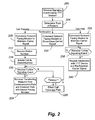
- FIG. 2 is a flowchart of a modem controller according to the first embodiment
- FIG. 3 is a block diagram of an architecture according to a second embodiment of the present invention.
- FIG. 4 is a block diagram of a modem according to an embodiment of the present invention.
- the invention will be illustrated below in conjunction with an exemplary communication system. Although well suited for use with, e.g., a system having an ACD or other similar contact processing switch, the invention is not limited to use with any particular type of communication system switch or configuration of system elements. Those skilled in the art will recognize that the disclosed techniques may be used in any communication application in which it is desirable to provide improved contact processing.
- FIG. 1 shows an illustrative embodiment of an enterprise architecture according to the present invention.
- the enterprise 100 includes a switching system 104 , an enterprise network 108 , a messaging server 112 , a human and/or autoattendant 116 , an IVR module 120 , a plurality of subscriber TTY communication devices 124 a - n , and a pool 128 of back-to-back modems.
- the architecture 100 may include other components (not shown) such a set of data stores or databases 114 containing contact, customer, and/or subscriber related information and other information that can enhance the value and efficiency of the contact, voice telecommunication devices, and other servers such as a scanner, VoIP software, video contact software, an IP voice server, a fax server, a web server, and an email server.
- a plurality of subscribers or working agents (not shown) operate the TTY communication devices 124 a to n (such as computer work stations or personal computers).
- switching system or “server” as used herein should be understood to include a PBX, an ACD, an enterprise switch, an enterprise server, or other type of telecommunications system switch or server, as well as other types of processor-based communication control devices such as media servers, computers, adjuncts, etc.
- the switching system 104 can be any integrated or nonintegrated (as shown) architecture for directing contacts to one or more telecommunication devices.
- the switching system 104 is a modified form of Avaya Inc.'s DefinityTM Private-Branch Exchange (PBX)-based ACD system; MultiVantageTM PBX, CRM Central 2000 ServerTM, Communication ManagerTM, S8300TM media server, and/or Avaya Interaction CenterTM.
- PBX Private-Branch Exchange
- MultiVantageTM PBX CRM Central 2000 ServerTM, Communication ManagerTM, S8300TM media server, and/or Avaya Interaction CenterTM.
- the switching system is a stored-program-controlled system that conventionally includes interfaces to external communication links, a communications switching fabric, service circuits (e.g., tone generators, announcement circuits, etc.), memory for storing control programs and data, and a processor (i.e., a computer) for executing the stored control programs to control the interfaces and the fabric and to provide automatic contact-distribution functionality.
- the switching system typically includes a network interface card (not shown) to provide services to the serviced telecommunication devices.
- Other types of known switches and servers are well known in the art and therefore not described in detail herein.
- the enterprise network 108 can be packet- and/or circuit-switched. It is preferably configured as a Local Area Network.
- the messaging server 112 , IVR module 120 , and attendant 116 are conventional.
- the TTY devices 124 are preferably carrier tone-based devices, which follow an established protocol such as an ITU or Bell modulation/demodulation protocol and transmits and/or receive data over a communication medium.
- TTY devices 124 may include or be individually or otherwise paired with telephones or other devices that provide call-control telephony signaling consistent with switching system 104 and/or modem controller 184 .
- the communication medium may be a telephone system (such as the PSTN), private branch exchange (PBX), or other media such as microwave link, coax, or fiber optic cable.
- ITU modems and Bell modems are examples of suitable TTY devices.
- the back-to-back modem pool 128 includes a plurality of pairings of back-to-back modems.
- Each pair 132 a - m includes an inward-facing modem 136 to communicate with internal or subscriber TTY devices 124 and an outward-facing modem 140 to communicate with modems and/or modem-based devices, such as external TTY device 144 , located outside the enterprise network.
- the outward or trunk-facing modem 140 is responsible for handling the handshake and carrier tone maintenance with far-end TTY devices on the network 176 .
- the inward, or station, facing modem 136 performs the same set of functions for devices on the enterprise network 108 .
- the Data Terminal Equipment or DTE ports of each modem pair are cross-connected in a “back-to-back” fashion.
- the modems in a modem pair are coupled together via their DTE interfaces as represented by line 172 .
- the DTE may be an adjunct to the switching system 104 , integrated into the switching system 104 , an external gateway to the switching system 104 , and the like.
- additional switching components could be positioned along line 172 allowing even greater configuration flexibility in the modem pool.
- lines 160 and 164 which are shown as separate lines for purposes of simplicity, represent allocated time slots of a Time-Division Multiplexed bus 168 that couples each modem pair to the switching system 104 .
- Inter-modem communications are preferably done using a text-based protocol, including binary strings of data or other types of information elements that are encapsulated within a data exchange protocol.
- each modem of the modem pairs is a “mu-law” modem because each modem couples directly to the above-mentioned time-division multiplexed bus as represented by lines 160 and 164 .
- the network 176 is preferably a circuit- or packet-switched Wide Area Network, such as the PSTN.
- Far-end TTY device 180 which is commonly a part of a second different enterprise network 192 , is preferably carrier tone-based and is external to the enterprise network. “External” means that the TTY device is not administered by the switching system 104 .
- Enterprise network 192 could include a modem controller 184 and modem pool 128 , depending on the application.
- FIG. 1 the configuration of the switching system, TTY devices, and other elements as shown in FIG. 1 is for purposes of illustration only and should not be construed as limiting the invention to any particular arrangement of elements.
- FIG. 4 shows an illustrative high-level block diagram of a modem in accordance with the principles of the invention.
- modem 400 includes a microprocessor 404 , memory 408 , a Digital Signal Processor or DSP 412 , e.g., for providing tone generator/detector and other modem functions, and Universal/Asynchronous Receive Transmit (UART) 416 for providing the DTE interface.
- DSP 412 Digital Signal Processor or DSP 412
- UART Universal/Asynchronous Receive Transmit
- Microprocessor 404 is coupled to DSP 412 via line 420 , which represents, address, data, control, and status leads.
- the memory can include selected text messages as mentioned below.
- the DTE interface 424 is with the other modem in the pair while the transmit and receive channels go towards either of the networks 108 or 176 , depending on whether the modem is facing towards the enterprise components or trunks (in the network 176 ), respectively.
- Other DTE protocols and implementations that provide equivalent functionality could be used.
- the back-to-back modems act cooperatively to maintain a constant carrier tone between the outward, or trunk, facing modem 140 and the TTY device 180 during switch-controlled operations, such as call transfers and call holds, that would, in the absence of a back-to-back modem pair, interrupt the carrier tone and cause disconnection of the call with the TTY device 180 .
- switch-controlled operations such as call transfers and call holds
- the selected device When the carrier tone between the inward-facing modem 136 and internal TTY device 124 , messaging server 112 , attendant 116 , or IVR module 120 is interrupted, the selected device re-establishes the carrier tone with another of the inward-facing modems 136 after the switch-controlled operation has been completed.
- connectivity with the TTY device 180 will be maintained by the trunk-facing modem 140 while the link between another station-facing modem 136 and the internal TTY device 124 is broken, and a new link established between the station-facing modem 136 and the internal TTY device 124 .
- the switching system includes a modem controller 184 and a control channel 188 extending between the switching system 104 and each pair of modems 132 in the modem pool 128 .
- the modem controller 184 monitors ordinary signaling mechanisms between the enterprise TTY device 124 and the switching system 104 and, in response, issues appropriate commands to the inward and outward-facing modems 136 and 140 .
- a call transfer originated by an internal TTY device 124 would generate a “call transfer request” and an appropriate number to which the call is to be transferred.
- the modem controller 184 commands the trunk-facing modem 140 to maintain its link with the far-end TTY device 180 , while the call transfer is performed.
- the modem controller 184 For a call drop request originated by the internal TTY device 124 , the modem controller 184 would signal the trunk-facing modem 140 to break the link, or interrupt the carrier tone, between the modem 140 and the TTY device 180 .
- a hold request or delay in transfer originated by the TTY device 124 would cause the controller 184 to signal the trunk-facing modem 140 to maintain carrier and possibly transmit text streams automatically to the TTY device 180 .
- An example of such a message stream is a periodic “please wait” announcement.
- the switching system 104 initiates call setup in response to receipt of a dialed number from a TTY device 124 .
- the outward-facing modem 140 contacts the TTY device 180 and performs a handshake.
- the outward-facing modem 140 signals the inward-facing modem 136 to initiate a handshake with the calling TTY device 124 .
- a pair of modems is allocated automatically to the call.
- a modem pair may be dedicated to each port to detect an incoming handshake signal.
- a subset of the ports may be associated with a dedicated number to be used only by TTY users.
- two-stage dialing is employed to establish a call between the calling TTY device 124 and the called TTY device 180 .
- the subscriber using the calling TTY device 124 first dials a number, such as “8” to access a modem pair in the modem pool 128 .
- a secondary dial tone is provided to the subscriber.
- a busy signal which may be text and/or voice, is provided to the calling TTY device 124 .
- the subscriber then dials the number of the TTY device 180 .
- the handshake exchange is first performed between the TTY device 124 and the inward-facing modem 136 and, when the call is initiated to the TTY device 180 , between the outward-facing modem 140 and the TTY device 180 .
- modem controller 184 The operation of the modem controller 184 will now be discussed with reference to FIG. 2 .
- call transfer, termination, and call hold are illustrative only. Other functional sequences may be followed to implement additional telephony features supported by switching system 104 and/or modem controller 184 .
- step 200 the modem controller 184 is notified that the subscriber of a TTY device 124 , during an existing session or call with an external TTY device 180 , has initiated a signaling event, such as by invoking a telephony feature.
- step 204 the modem controller 184 determines the type of signaling event, or type of feature, invoked.
- the modem controller follows the logic branch on the far left of FIG. 2 .
- the modem agent commands out-of-band the outward-facing modem 140 , in a selected modem pair in the communication path between the TTY devices 124 and 180 , to maintain carrier tone notwithstanding loss of carrier tone by the inward-facing modem 136 .
- the switching system 104 may receive from the subscriber, a dialed number to which the call is to be transferred. As will be appreciated, when the “call transfer” button is first pressed the subscriber may receive a secondary dial tone to dial the desired number to which the call is to be transferred.
- step 216 the switching system 104 initiates a call to the dialed number.
- Call initiation includes not only establishing connection between the transferring TTY device and the dialed enterprise component but also completing the handshake procedure therebetween. At this point, there is no connection between the TTY device and inward-facing modem.
- decision diamond 220 the switching system 104 determines whether a further signaling event has been received. Typically, the further signaling event is a further “call transfer” command. When the signaling event is received, the transferring TTY device 124 , in step 224 , is removed automatically from the communication path with the component to which the call is to be transferred.
- the transferee component and the inward-facing modem 136 complete the handshake procedure.
- the switching system timeouts and the call in step 228 , is processed according to call coverage set up for the dialed component. Call coverage, for example, may require the call to be transferred to the messaging server 112 to leave a text message for the subscriber associated with the dialed component.
- the modem controller, or outward modem can send a recurring text message to the TTY device 180 .
- the modem controller follows the logic branch in the middle of FIG. 2 .
- the modem controller in step 232 commands the outward-facing modem 140 to interrupt or drop the carrier tone between the outward-facing modem 140 and the TTY device 180 , thereby disconnecting the call with the TTY device 180 .
- step 208 is performed but step 232 is not performed.
- the outward-facing modem 140 assumes that, unless a contrary command is received within a selected time of carrier tone interruption between the inward-facing modem and an enterprise component, the carrier tone with the TTY device 180 is to be dropped.
- step 232 but not step 208 is performed because the outward-facing modem 140 assumes that the carrier tone is to be maintained unless a contrary command is received within a selected time of carrier tone interruption between the inward-facing modem and an enterprise component.
- the modem controller follows the logic branch on the far left of FIG. 2 .
- the modem agent commands the outward-facing modem 140 , in a selected modem pair in the communication path between the TTY devices 124 and 180 , to maintain carrier tone notwithstanding loss of carrier tone by the inward-facing modem 136 .
- decision diamond 236 the switching system 104 determines whether a further signaling event has occurred. Typically, the further signaling event is the subscriber again depressing the hold button to cause the call to be taken off hold. If not, the switching system 104 returns to decision diamond 236 . If the further signaling event has occurred, the modem controller 184 commands the inward-facing modem 136 to repeat the handshake procedure with the respective subscriber's TTY device 124 to re-establish the carrier tone.
- first and second enterprise networks 300 and 304 are depicted.
- Each enterprise network includes a switching system 104 , a modem controller, 308 , an inward-facing modem 312 , and a TTY device 124 .
- the enterprise networks are further interconnected by network 108 .
- the inward-facing modems 312 maintain and re-establish carrier tone with its respective TTY device in response to telecommunication operations as noted above.
- Text information for the communication between the TTY devices is exchanged between the modems 312 in the first and second enterprise networks 300 and 304 through a data (text) exchange protocol suitable for circuit-switched networks.
- suitable text-based protocols include fax transmission standards.
- the following standards specify the fax data rate and modulation schemes: ITU V.17 defines half-duplex 14.4 kbps modulation; ITU V.29 defines half-duplex 9.6 kbps modulation; and ITU V.27ter defines half-duplex 4.8 kbps modulation.
- ITU T.4 defines the fax image encoding scheme, generally know as Group 3. Most fax equipment or services currently provided are Group 3 faxes.
- ITU V.21 channel 2 specifies a 300 bps frequency-shift-keying (FSK) modulation used during fax handshaking procedures, which are specified in ITU T.30.
- FSK frequency-shift-keying
- the function of handshaking is to allow each fax endpoint to determine the capabilities of the opposite fax endpoint such as highest supported data rate, page resolution, page size, etc. It should be noted that the ITU T.30 fax handshaking protocol allows for manual operation, where a user can originate or answer a call using a phone connected to the fax device, and then switch to fax mode, and an automatic mode of operation.
- the switching system 104 When the call is to be terminated or disconnected, the switching system 104 on the end at which the first TTY device changes to an on-hook, or disconnected state, sends a disconnect request out-of-band to the other switching system 104 .
- the modem controller in the other switching system 104 commands in-band its respective modem to drop carrier tone with the internal TTY device.
- the modem controller on the side of the disconnecting TTY device can instruct its respective modem to send to the far end modem a text command to disconnect the call.
- the disconnect command can be sent out-of-band between the two switching systems.
- existing signaling protocols and standards govern the exchange of telecommunication information between switches of differing enterprise networks.
- the inward-facing modem is configured to operate in the Baudot protocol alone or in both the Baudot protocol and carrier tone-based protocol(s).
- the inward-facing modem is a dual purpose modem that has discrete first and second modes, each mode corresponding to one of the Baudot protocol and carrier tone-based protocol.
- a user of external TTY device 180 can input a mode identifier indicating when he or she desires to be in the Baudot-only or carrier tone-based protocol.
- the inward-facing modem enters into the desired mode.
- the modem controller 184 which will have access to the capabilities of the internal enterprise component connected to the TTY device 180 , can, when the device is a Baudot only device, command the inward-facing modem 136 to enter the Baudot only mode.
- the inward-facing modem in connection with the outward-facing modem, translate carrier tone-based text signals into corresponding Baudot text signals.
- the outward-facing modem 140 handles the handshake with the external carrier tone-based TTY device.
- the TTY device can provide a DTMF indicator, such as “*24” that would indicate to the outward-facing modem that the following text character should be configured into a corresponding DTMF signal generated by the inward-facing modem (when in the Baudot mode).
- the outward-facing modem can command the inward-facing modem to generate the DTMF signal via the line 172 .
- the TTY user could interact with the messaging server 112 , attendant 116 , or IVR module 120 , using a mixture of Baudot and DTMF signals, even when his or her device is carrier tone-based and not a Baudot-compatible device and notwithstanding the fact that the messaging server, attendant, or IVR module or other type of auto response unit is existing Baudot-compatible only.
- This configuration could also support remote telephony feature invocation using DTMF signals generated by the inward-facing modem 136 when in the Baudot mode. Feature invocation is done using DTMF equivalents to feature access codes.
- This embodiment can overcome the differences between carrier tone-based and Baudot protocols, which currently make such devices incompatible with one another.
- the differences include: (1) Baudot TTYs encode text characters with the five bit Baudot code, while carrier tone-based TTYs use an ASCII encoding, also known as the ANSI X3.4-1977 or ASCII-77 encoding, (2) Baudot TTYs, unlike carrier tone-based TTYs, do not provide for parity bits, (3) Baudot TTYs in the United States transmit/receive only at 45.45 bits per second, and (4) Baudot TTYs, unlike carrier tone-based TTYs, use frequency shift keying modulation/demodulation at frequencies of 1400 and 1800 Hz.
- the memory 408 of the outward-facing modem buffers signals received from a far-end TTY device while the telecommunication operation, causing loss of carrier tone within the enterprise network, is being performed.
- This embodiment is particularly important for a TTY conference call among more than two participants.
- the buffered information is transmitted to the inward-facing modem, and to its enterprise component, when the inward-facing modem and its enterprise component (re-)establish contact.
- dedicated hardware implementations including, but not limited to, Application Specific Integrated Circuits or ASICs, programmable logic arrays, and other hardware devices can likewise be constructed to implement the methods described herein.
- alternative software implementations including, but not limited to, distributed processing or component/object distributed processing, parallel processing, or virtual machine processing can also be constructed to implement the methods described herein.
- the software implementations of the present invention are optionally stored on a tangible storage medium, such as a magnetic medium like a disk or tape, a magneto-optical or optical medium like a disk, or a solid state medium like a memory card or other package that houses one or more read-only (non-volatile) memories.
- a digital file attachment to e-mail or other self-contained information archive or set of archives is considered a distribution medium equivalent to a tangible storage medium. Accordingly, the invention is considered to include a tangible storage medium or distribution medium and prior art-recognized equivalents and successor media, in which the software implementations of the present invention are stored.
- the present invention in various embodiments, includes components, methods, processes, systems and/or apparatus substantially as depicted and described herein, including various embodiments, subcombinations, and subsets thereof. Those of skill in the art will understand how to make and use the present invention after understanding the present disclosure.
- the present invention in various embodiments, includes providing devices and processes in the absence of items not depicted and/or described herein or in various embodiments hereof, including in the absence of such items as may have been used in previous devices or processes, e.g., for improving performance, achieving ease and ⁇ or reducing cost of implementation.
Abstract
Description
Claims (10)
Priority Applications (1)
| Application Number | Priority Date | Filing Date | Title |
|---|---|---|---|
| US11/482,027 US8031842B1 (en) | 2006-07-05 | 2006-07-05 | Dual modern architecture to support the transfer of non-Baudot TTY telephone calls |
Applications Claiming Priority (1)
| Application Number | Priority Date | Filing Date | Title |
|---|---|---|---|
| US11/482,027 US8031842B1 (en) | 2006-07-05 | 2006-07-05 | Dual modern architecture to support the transfer of non-Baudot TTY telephone calls |
Publications (1)
| Publication Number | Publication Date |
|---|---|
| US8031842B1 true US8031842B1 (en) | 2011-10-04 |
Family
ID=44676781
Family Applications (1)
| Application Number | Title | Priority Date | Filing Date |
|---|---|---|---|
| US11/482,027 Expired - Fee Related US8031842B1 (en) | 2006-07-05 | 2006-07-05 | Dual modern architecture to support the transfer of non-Baudot TTY telephone calls |
Country Status (1)
| Country | Link |
|---|---|
| US (1) | US8031842B1 (en) |
Citations (15)
| Publication number | Priority date | Publication date | Assignee | Title |
|---|---|---|---|---|
| US5253285A (en) * | 1990-12-13 | 1993-10-12 | Alheim Curtis C | Automated interactive telephone communication system for TDD users |
| US5351288A (en) | 1988-10-11 | 1994-09-27 | Ultratec, Inc. | Voice bridge for a relay center |
| US5684825A (en) | 1994-03-23 | 1997-11-04 | Paradyne Corporation | Independently switched voice and data calls using a simultaneous voice and data modem |
| US5787364A (en) * | 1995-01-30 | 1998-07-28 | Paradyne Corporation | Transparent call progress |
| US5870457A (en) * | 1997-06-30 | 1999-02-09 | Mci Worldcom, Inc. | Method and system for transferring a data modem call |
| US5905476A (en) | 1994-07-05 | 1999-05-18 | Nxi Communications, Inc. | ITU/TDD modem |
| US5940475A (en) * | 1997-05-30 | 1999-08-17 | Northern Telecom Limited | Telephone system integrated text based communication apparatus and system to enhance access for TDD and/or TTY devices |
| US6011968A (en) | 1995-12-18 | 2000-01-04 | Paradyne Corporation | Cellular modem pool for sending faxes over cellular communications channels |
| US20020085703A1 (en) * | 2001-01-02 | 2002-07-04 | Proctor Rod L. | Facility and method for cellular data communication between hearing impaired users and emergency service centers |
| US6442242B1 (en) * | 1999-06-25 | 2002-08-27 | Verizon Services Corporation | Multifunction autoattendant system and method of operation thereof |
| US6480531B1 (en) | 1998-10-23 | 2002-11-12 | Cisco Technology, Inc. | Method and apparatus of testing modems in a networking environment |
| US6724886B1 (en) * | 2001-02-15 | 2004-04-20 | Sprint Communications Company L.P. | System and method for assuring connection of TTY telephone calls to a call center |
| US20060058049A1 (en) | 1997-03-25 | 2006-03-16 | Mclaughlin Thomas J | Network communication system |
| US7567653B1 (en) * | 2005-03-22 | 2009-07-28 | Avaya Inc. | Method by which call centers can vector inbound TTY calls automatically to TTY-enabled resources |
| US7587034B2 (en) * | 1999-04-12 | 2009-09-08 | Silicon Laboratories Inc. | Use of modem on hold for network management and telephone access |
-
2006
- 2006-07-05 US US11/482,027 patent/US8031842B1/en not_active Expired - Fee Related
Patent Citations (15)
| Publication number | Priority date | Publication date | Assignee | Title |
|---|---|---|---|---|
| US5351288A (en) | 1988-10-11 | 1994-09-27 | Ultratec, Inc. | Voice bridge for a relay center |
| US5253285A (en) * | 1990-12-13 | 1993-10-12 | Alheim Curtis C | Automated interactive telephone communication system for TDD users |
| US5684825A (en) | 1994-03-23 | 1997-11-04 | Paradyne Corporation | Independently switched voice and data calls using a simultaneous voice and data modem |
| US5905476A (en) | 1994-07-05 | 1999-05-18 | Nxi Communications, Inc. | ITU/TDD modem |
| US5787364A (en) * | 1995-01-30 | 1998-07-28 | Paradyne Corporation | Transparent call progress |
| US6011968A (en) | 1995-12-18 | 2000-01-04 | Paradyne Corporation | Cellular modem pool for sending faxes over cellular communications channels |
| US20060058049A1 (en) | 1997-03-25 | 2006-03-16 | Mclaughlin Thomas J | Network communication system |
| US5940475A (en) * | 1997-05-30 | 1999-08-17 | Northern Telecom Limited | Telephone system integrated text based communication apparatus and system to enhance access for TDD and/or TTY devices |
| US5870457A (en) * | 1997-06-30 | 1999-02-09 | Mci Worldcom, Inc. | Method and system for transferring a data modem call |
| US6480531B1 (en) | 1998-10-23 | 2002-11-12 | Cisco Technology, Inc. | Method and apparatus of testing modems in a networking environment |
| US7587034B2 (en) * | 1999-04-12 | 2009-09-08 | Silicon Laboratories Inc. | Use of modem on hold for network management and telephone access |
| US6442242B1 (en) * | 1999-06-25 | 2002-08-27 | Verizon Services Corporation | Multifunction autoattendant system and method of operation thereof |
| US20020085703A1 (en) * | 2001-01-02 | 2002-07-04 | Proctor Rod L. | Facility and method for cellular data communication between hearing impaired users and emergency service centers |
| US6724886B1 (en) * | 2001-02-15 | 2004-04-20 | Sprint Communications Company L.P. | System and method for assuring connection of TTY telephone calls to a call center |
| US7567653B1 (en) * | 2005-03-22 | 2009-07-28 | Avaya Inc. | Method by which call centers can vector inbound TTY calls automatically to TTY-enabled resources |
Non-Patent Citations (3)
| Title |
|---|
| Broersma et al.; Throughput of ADSL Modems; Memorandum No. 1482; 17 pages. |
| Textgateway "T-Hyubrid"-connects analog with digital; http://www.omnitor.se/eng/textgateway-en.html; printed on May 17, 2006; 4 pages. |
| VSAT Plus II Version 2, System Overview Revision 06, PolarSat, Nov. 2005, Final. |
Similar Documents
| Publication | Publication Date | Title |
|---|---|---|
| US6636508B1 (en) | Network resource conservation system | |
| US5602846A (en) | Simultaneous voice and data call establishment using a simultaneous voice and data modem pool and private branch exchange facilities | |
| US6178183B1 (en) | Method and apparatus for receiving conventional telephone calls while connected to the internet | |
| US6188688B1 (en) | Method and apparatus for placing telephone calls while connected to the internet | |
| US5684825A (en) | Independently switched voice and data calls using a simultaneous voice and data modem | |
| AU708959B2 (en) | Method to provide voice call notification and control messaging over a data path | |
| US6236653B1 (en) | Local telephone service over a cable network using packet voice | |
| US5699413A (en) | Voice data modem, voice data method and voice data modem system | |
| US6167043A (en) | Method and system for small office and home office telephone private branch exchange allowing simultaneous data and voice communications | |
| US6125177A (en) | Telephone communications network with enhanced signaling and call routing | |
| US7142560B2 (en) | System and method for virtual multiline telephony in a home-network telephone | |
| US6487196B1 (en) | System and method for simulating telephone use in a network telephone system | |
| EP0583094B1 (en) | ISDN-based system for making a video call | |
| US20020097708A1 (en) | System for interconnecting packet-switched and circuit-switched voice communications | |
| KR100281090B1 (en) | Protocol message transmission system and message transmission method using the same | |
| EP1323287A1 (en) | System for and method of extending a pbx phone port to a remote phone device | |
| EP0711052A1 (en) | Improvements in or relating to telecommunication systems | |
| US8031842B1 (en) | Dual modern architecture to support the transfer of non-Baudot TTY telephone calls | |
| KR20010105042A (en) | Multiple telecommunication coupling device | |
| Cisco | Cisco Voice Telephony | |
| JP2001333185A (en) | Multimedia message transmission based on internet protocol standards | |
| Cisco | Voice over IP Commands | |
| Cisco | Cisco IOS Voice, Video, and Fax Commands: D through F | |
| US6483904B1 (en) | Method and system for high-speed interface access to a computer network using a subscriber telephone line | |
| JP2716984B2 (en) | Communication method |
Legal Events
| Date | Code | Title | Description |
|---|---|---|---|
| AS | Assignment |
Owner name: CITIBANK, N.A., AS ADMINISTRATIVE AGENT, NEW YORK Free format text: SECURITY AGREEMENT;ASSIGNORS:AVAYA, INC.;AVAYA TECHNOLOGY LLC;OCTEL COMMUNICATIONS LLC;AND OTHERS;REEL/FRAME:020156/0149 Effective date: 20071026 |
|
| AS | Assignment |
Owner name: CITICORP USA, INC., AS ADMINISTRATIVE AGENT, NEW YORK Free format text: SECURITY AGREEMENT;ASSIGNORS:AVAYA, INC.;AVAYA TECHNOLOGY LLC;OCTEL COMMUNICATIONS LLC;AND OTHERS;REEL/FRAME:020166/0705 Effective date: 20071026 Owner name: CITICORP USA, INC., AS ADMINISTRATIVE AGENT, NEW Y Free format text: SECURITY AGREEMENT;ASSIGNORS:AVAYA, INC.;AVAYA TECHNOLOGY LLC;OCTEL COMMUNICATIONS LLC;AND OTHERS;REEL/FRAME:020166/0705 Effective date: 20071026 |
|
| AS | Assignment |
Owner name: AVAYA INC, NEW JERSEY Free format text: REASSIGNMENT;ASSIGNOR:AVAYA TECHNOLOGY LLC;REEL/FRAME:021156/0689 Effective date: 20080625 |
|
| AS | Assignment |
Owner name: AVAYA TECHNOLOGY LLC, NEW JERSEY Free format text: ASSIGNMENT OF ASSIGNORS INTEREST;ASSIGNORS:MICHAELIS, PAUL ROLLER;WINDHAUSEN, RICHARD A.;REEL/FRAME:024758/0647 Effective date: 20060629 |
|
| FEPP | Fee payment procedure |
Free format text: PAYOR NUMBER ASSIGNED (ORIGINAL EVENT CODE: ASPN); ENTITY STATUS OF PATENT OWNER: LARGE ENTITY |
|
| AS | Assignment |
Owner name: BANK OF NEW YORK MELLON TRUST, NA, AS NOTES COLLATERAL AGENT, THE, PENNSYLVANIA Free format text: SECURITY AGREEMENT;ASSIGNOR:AVAYA INC., A DELAWARE CORPORATION;REEL/FRAME:025863/0535 Effective date: 20110211 Owner name: BANK OF NEW YORK MELLON TRUST, NA, AS NOTES COLLAT Free format text: SECURITY AGREEMENT;ASSIGNOR:AVAYA INC., A DELAWARE CORPORATION;REEL/FRAME:025863/0535 Effective date: 20110211 |
|
| ZAAA | Notice of allowance and fees due |
Free format text: ORIGINAL CODE: NOA |
|
| ZAAB | Notice of allowance mailed |
Free format text: ORIGINAL CODE: MN/=. |
|
| STCF | Information on status: patent grant |
Free format text: PATENTED CASE |
|
| CC | Certificate of correction | ||
| AS | Assignment |
Owner name: BANK OF NEW YORK MELLON TRUST COMPANY, N.A., THE, PENNSYLVANIA Free format text: SECURITY AGREEMENT;ASSIGNOR:AVAYA, INC.;REEL/FRAME:030083/0639 Effective date: 20130307 Owner name: BANK OF NEW YORK MELLON TRUST COMPANY, N.A., THE, Free format text: SECURITY AGREEMENT;ASSIGNOR:AVAYA, INC.;REEL/FRAME:030083/0639 Effective date: 20130307 |
|
| FPAY | Fee payment |
Year of fee payment: 4 |
|
| AS | Assignment |
Owner name: CITIBANK, N.A., AS ADMINISTRATIVE AGENT, NEW YORK Free format text: SECURITY INTEREST;ASSIGNORS:AVAYA INC.;AVAYA INTEGRATED CABINET SOLUTIONS INC.;OCTEL COMMUNICATIONS CORPORATION;AND OTHERS;REEL/FRAME:041576/0001 Effective date: 20170124 |
|
| AS | Assignment |
Owner name: OCTEL COMMUNICATIONS LLC (FORMERLY KNOWN AS OCTEL COMMUNICATIONS CORPORATION), CALIFORNIA Free format text: BANKRUPTCY COURT ORDER RELEASING ALL LIENS INCLUDING THE SECURITY INTEREST RECORDED AT REEL/FRAME 041576/0001;ASSIGNOR:CITIBANK, N.A.;REEL/FRAME:044893/0531 Effective date: 20171128 Owner name: AVAYA INTEGRATED CABINET SOLUTIONS INC., CALIFORNIA Free format text: BANKRUPTCY COURT ORDER RELEASING ALL LIENS INCLUDING THE SECURITY INTEREST RECORDED AT REEL/FRAME 041576/0001;ASSIGNOR:CITIBANK, N.A.;REEL/FRAME:044893/0531 Effective date: 20171128 Owner name: AVAYA INC., CALIFORNIA Free format text: BANKRUPTCY COURT ORDER RELEASING ALL LIENS INCLUDING THE SECURITY INTEREST RECORDED AT REEL/FRAME 025863/0535;ASSIGNOR:THE BANK OF NEW YORK MELLON TRUST, NA;REEL/FRAME:044892/0001 Effective date: 20171128 Owner name: AVAYA INTEGRATED CABINET SOLUTIONS INC., CALIFORNI Free format text: BANKRUPTCY COURT ORDER RELEASING ALL LIENS INCLUDING THE SECURITY INTEREST RECORDED AT REEL/FRAME 041576/0001;ASSIGNOR:CITIBANK, N.A.;REEL/FRAME:044893/0531 Effective date: 20171128 Owner name: VPNET TECHNOLOGIES, INC., CALIFORNIA Free format text: BANKRUPTCY COURT ORDER RELEASING ALL LIENS INCLUDING THE SECURITY INTEREST RECORDED AT REEL/FRAME 041576/0001;ASSIGNOR:CITIBANK, N.A.;REEL/FRAME:044893/0531 Effective date: 20171128 Owner name: OCTEL COMMUNICATIONS LLC (FORMERLY KNOWN AS OCTEL Free format text: BANKRUPTCY COURT ORDER RELEASING ALL LIENS INCLUDING THE SECURITY INTEREST RECORDED AT REEL/FRAME 041576/0001;ASSIGNOR:CITIBANK, N.A.;REEL/FRAME:044893/0531 Effective date: 20171128 Owner name: AVAYA INC., CALIFORNIA Free format text: BANKRUPTCY COURT ORDER RELEASING ALL LIENS INCLUDING THE SECURITY INTEREST RECORDED AT REEL/FRAME 041576/0001;ASSIGNOR:CITIBANK, N.A.;REEL/FRAME:044893/0531 Effective date: 20171128 Owner name: AVAYA INC., CALIFORNIA Free format text: BANKRUPTCY COURT ORDER RELEASING ALL LIENS INCLUDING THE SECURITY INTEREST RECORDED AT REEL/FRAME 030083/0639;ASSIGNOR:THE BANK OF NEW YORK MELLON TRUST COMPANY, N.A.;REEL/FRAME:045012/0666 Effective date: 20171128 |
|
| AS | Assignment |
Owner name: VPNET TECHNOLOGIES, INC., NEW JERSEY Free format text: RELEASE BY SECURED PARTY;ASSIGNOR:CITICORP USA, INC.;REEL/FRAME:045032/0213 Effective date: 20171215 Owner name: AVAYA TECHNOLOGY, LLC, NEW JERSEY Free format text: RELEASE BY SECURED PARTY;ASSIGNOR:CITICORP USA, INC.;REEL/FRAME:045032/0213 Effective date: 20171215 Owner name: OCTEL COMMUNICATIONS LLC, CALIFORNIA Free format text: RELEASE BY SECURED PARTY;ASSIGNOR:CITICORP USA, INC.;REEL/FRAME:045032/0213 Effective date: 20171215 Owner name: AVAYA, INC., CALIFORNIA Free format text: RELEASE BY SECURED PARTY;ASSIGNOR:CITICORP USA, INC.;REEL/FRAME:045032/0213 Effective date: 20171215 Owner name: SIERRA HOLDINGS CORP., NEW JERSEY Free format text: RELEASE BY SECURED PARTY;ASSIGNOR:CITICORP USA, INC.;REEL/FRAME:045032/0213 Effective date: 20171215 |
|
| AS | Assignment |
Owner name: GOLDMAN SACHS BANK USA, AS COLLATERAL AGENT, NEW YORK Free format text: SECURITY INTEREST;ASSIGNORS:AVAYA INC.;AVAYA INTEGRATED CABINET SOLUTIONS LLC;OCTEL COMMUNICATIONS LLC;AND OTHERS;REEL/FRAME:045034/0001 Effective date: 20171215 Owner name: GOLDMAN SACHS BANK USA, AS COLLATERAL AGENT, NEW Y Free format text: SECURITY INTEREST;ASSIGNORS:AVAYA INC.;AVAYA INTEGRATED CABINET SOLUTIONS LLC;OCTEL COMMUNICATIONS LLC;AND OTHERS;REEL/FRAME:045034/0001 Effective date: 20171215 |
|
| AS | Assignment |
Owner name: CITIBANK, N.A., AS COLLATERAL AGENT, NEW YORK Free format text: SECURITY INTEREST;ASSIGNORS:AVAYA INC.;AVAYA INTEGRATED CABINET SOLUTIONS LLC;OCTEL COMMUNICATIONS LLC;AND OTHERS;REEL/FRAME:045124/0026 Effective date: 20171215 |
|
| MAFP | Maintenance fee payment |
Free format text: PAYMENT OF MAINTENANCE FEE, 8TH YEAR, LARGE ENTITY (ORIGINAL EVENT CODE: M1552); ENTITY STATUS OF PATENT OWNER: LARGE ENTITY Year of fee payment: 8 |
|
| AS | Assignment |
Owner name: WILMINGTON TRUST, NATIONAL ASSOCIATION, MINNESOTA Free format text: SECURITY INTEREST;ASSIGNORS:AVAYA INC.;AVAYA MANAGEMENT L.P.;INTELLISIST, INC.;AND OTHERS;REEL/FRAME:053955/0436 Effective date: 20200925 |
|
| AS | Assignment |
Owner name: VPNET TECHNOLOGIES, CALIFORNIA Free format text: BANKRUPTCY COURT ORDER RELEASING THE SECURITY INTEREST RECORDED AT REEL/FRAME 020156/0149;ASSIGNOR:CITIBANK, N.A., AS ADMINISTRATIVE AGENT;REEL/FRAME:060953/0412 Effective date: 20171128 Owner name: OCTEL COMMUNICATIONS LLC, CALIFORNIA Free format text: BANKRUPTCY COURT ORDER RELEASING THE SECURITY INTEREST RECORDED AT REEL/FRAME 020156/0149;ASSIGNOR:CITIBANK, N.A., AS ADMINISTRATIVE AGENT;REEL/FRAME:060953/0412 Effective date: 20171128 Owner name: AVAYA TECHNOLOGY LLC, CALIFORNIA Free format text: BANKRUPTCY COURT ORDER RELEASING THE SECURITY INTEREST RECORDED AT REEL/FRAME 020156/0149;ASSIGNOR:CITIBANK, N.A., AS ADMINISTRATIVE AGENT;REEL/FRAME:060953/0412 Effective date: 20171128 Owner name: AVAYA, INC., CALIFORNIA Free format text: BANKRUPTCY COURT ORDER RELEASING THE SECURITY INTEREST RECORDED AT REEL/FRAME 020156/0149;ASSIGNOR:CITIBANK, N.A., AS ADMINISTRATIVE AGENT;REEL/FRAME:060953/0412 Effective date: 20171128 |
|
| AS | Assignment |
Owner name: WILMINGTON TRUST, NATIONAL ASSOCIATION, AS COLLATERAL AGENT, DELAWARE Free format text: INTELLECTUAL PROPERTY SECURITY AGREEMENT;ASSIGNORS:AVAYA INC.;INTELLISIST, INC.;AVAYA MANAGEMENT L.P.;AND OTHERS;REEL/FRAME:061087/0386 Effective date: 20220712 |
|
| AS | Assignment |
Owner name: AVAYA INTEGRATED CABINET SOLUTIONS LLC, NEW JERSEY Free format text: RELEASE OF SECURITY INTEREST IN PATENTS AT REEL 45124/FRAME 0026;ASSIGNOR:CITIBANK, N.A., AS COLLATERAL AGENT;REEL/FRAME:063457/0001 Effective date: 20230403 Owner name: AVAYA MANAGEMENT L.P., NEW JERSEY Free format text: RELEASE OF SECURITY INTEREST IN PATENTS AT REEL 45124/FRAME 0026;ASSIGNOR:CITIBANK, N.A., AS COLLATERAL AGENT;REEL/FRAME:063457/0001 Effective date: 20230403 Owner name: AVAYA INC., NEW JERSEY Free format text: RELEASE OF SECURITY INTEREST IN PATENTS AT REEL 45124/FRAME 0026;ASSIGNOR:CITIBANK, N.A., AS COLLATERAL AGENT;REEL/FRAME:063457/0001 Effective date: 20230403 Owner name: AVAYA HOLDINGS CORP., NEW JERSEY Free format text: RELEASE OF SECURITY INTEREST IN PATENTS AT REEL 45124/FRAME 0026;ASSIGNOR:CITIBANK, N.A., AS COLLATERAL AGENT;REEL/FRAME:063457/0001 Effective date: 20230403 |
|
| AS | Assignment |
Owner name: WILMINGTON SAVINGS FUND SOCIETY, FSB (COLLATERAL AGENT), DELAWARE Free format text: INTELLECTUAL PROPERTY SECURITY AGREEMENT;ASSIGNORS:AVAYA MANAGEMENT L.P.;AVAYA INC.;INTELLISIST, INC.;AND OTHERS;REEL/FRAME:063742/0001 Effective date: 20230501 |
|
| AS | Assignment |
Owner name: CITIBANK, N.A., AS COLLATERAL AGENT, NEW YORK Free format text: INTELLECTUAL PROPERTY SECURITY AGREEMENT;ASSIGNORS:AVAYA INC.;AVAYA MANAGEMENT L.P.;INTELLISIST, INC.;REEL/FRAME:063542/0662 Effective date: 20230501 |
|
| AS | Assignment |
Owner name: AVAYA MANAGEMENT L.P., NEW JERSEY Free format text: RELEASE OF SECURITY INTEREST IN PATENTS (REEL/FRAME 045034/0001);ASSIGNOR:GOLDMAN SACHS BANK USA., AS COLLATERAL AGENT;REEL/FRAME:063779/0622 Effective date: 20230501 Owner name: CAAS TECHNOLOGIES, LLC, NEW JERSEY Free format text: RELEASE OF SECURITY INTEREST IN PATENTS (REEL/FRAME 045034/0001);ASSIGNOR:GOLDMAN SACHS BANK USA., AS COLLATERAL AGENT;REEL/FRAME:063779/0622 Effective date: 20230501 Owner name: HYPERQUALITY II, LLC, NEW JERSEY Free format text: RELEASE OF SECURITY INTEREST IN PATENTS (REEL/FRAME 045034/0001);ASSIGNOR:GOLDMAN SACHS BANK USA., AS COLLATERAL AGENT;REEL/FRAME:063779/0622 Effective date: 20230501 Owner name: HYPERQUALITY, INC., NEW JERSEY Free format text: RELEASE OF SECURITY INTEREST IN PATENTS (REEL/FRAME 045034/0001);ASSIGNOR:GOLDMAN SACHS BANK USA., AS COLLATERAL AGENT;REEL/FRAME:063779/0622 Effective date: 20230501 Owner name: ZANG, INC. (FORMER NAME OF AVAYA CLOUD INC.), NEW JERSEY Free format text: RELEASE OF SECURITY INTEREST IN PATENTS (REEL/FRAME 045034/0001);ASSIGNOR:GOLDMAN SACHS BANK USA., AS COLLATERAL AGENT;REEL/FRAME:063779/0622 Effective date: 20230501 Owner name: VPNET TECHNOLOGIES, INC., NEW JERSEY Free format text: RELEASE OF SECURITY INTEREST IN PATENTS (REEL/FRAME 045034/0001);ASSIGNOR:GOLDMAN SACHS BANK USA., AS COLLATERAL AGENT;REEL/FRAME:063779/0622 Effective date: 20230501 Owner name: OCTEL COMMUNICATIONS LLC, NEW JERSEY Free format text: RELEASE OF SECURITY INTEREST IN PATENTS (REEL/FRAME 045034/0001);ASSIGNOR:GOLDMAN SACHS BANK USA., AS COLLATERAL AGENT;REEL/FRAME:063779/0622 Effective date: 20230501 Owner name: AVAYA INTEGRATED CABINET SOLUTIONS LLC, NEW JERSEY Free format text: RELEASE OF SECURITY INTEREST IN PATENTS (REEL/FRAME 045034/0001);ASSIGNOR:GOLDMAN SACHS BANK USA., AS COLLATERAL AGENT;REEL/FRAME:063779/0622 Effective date: 20230501 Owner name: INTELLISIST, INC., NEW JERSEY Free format text: RELEASE OF SECURITY INTEREST IN PATENTS (REEL/FRAME 045034/0001);ASSIGNOR:GOLDMAN SACHS BANK USA., AS COLLATERAL AGENT;REEL/FRAME:063779/0622 Effective date: 20230501 Owner name: AVAYA INC., NEW JERSEY Free format text: RELEASE OF SECURITY INTEREST IN PATENTS (REEL/FRAME 045034/0001);ASSIGNOR:GOLDMAN SACHS BANK USA., AS COLLATERAL AGENT;REEL/FRAME:063779/0622 Effective date: 20230501 Owner name: AVAYA INTEGRATED CABINET SOLUTIONS LLC, NEW JERSEY Free format text: RELEASE OF SECURITY INTEREST IN PATENTS (REEL/FRAME 53955/0436);ASSIGNOR:WILMINGTON TRUST, NATIONAL ASSOCIATION, AS NOTES COLLATERAL AGENT;REEL/FRAME:063705/0023 Effective date: 20230501 Owner name: INTELLISIST, INC., NEW JERSEY Free format text: RELEASE OF SECURITY INTEREST IN PATENTS (REEL/FRAME 53955/0436);ASSIGNOR:WILMINGTON TRUST, NATIONAL ASSOCIATION, AS NOTES COLLATERAL AGENT;REEL/FRAME:063705/0023 Effective date: 20230501 Owner name: AVAYA INC., NEW JERSEY Free format text: RELEASE OF SECURITY INTEREST IN PATENTS (REEL/FRAME 53955/0436);ASSIGNOR:WILMINGTON TRUST, NATIONAL ASSOCIATION, AS NOTES COLLATERAL AGENT;REEL/FRAME:063705/0023 Effective date: 20230501 Owner name: AVAYA MANAGEMENT L.P., NEW JERSEY Free format text: RELEASE OF SECURITY INTEREST IN PATENTS (REEL/FRAME 53955/0436);ASSIGNOR:WILMINGTON TRUST, NATIONAL ASSOCIATION, AS NOTES COLLATERAL AGENT;REEL/FRAME:063705/0023 Effective date: 20230501 Owner name: AVAYA INTEGRATED CABINET SOLUTIONS LLC, NEW JERSEY Free format text: RELEASE OF SECURITY INTEREST IN PATENTS (REEL/FRAME 61087/0386);ASSIGNOR:WILMINGTON TRUST, NATIONAL ASSOCIATION, AS NOTES COLLATERAL AGENT;REEL/FRAME:063690/0359 Effective date: 20230501 Owner name: INTELLISIST, INC., NEW JERSEY Free format text: RELEASE OF SECURITY INTEREST IN PATENTS (REEL/FRAME 61087/0386);ASSIGNOR:WILMINGTON TRUST, NATIONAL ASSOCIATION, AS NOTES COLLATERAL AGENT;REEL/FRAME:063690/0359 Effective date: 20230501 Owner name: AVAYA INC., NEW JERSEY Free format text: RELEASE OF SECURITY INTEREST IN PATENTS (REEL/FRAME 61087/0386);ASSIGNOR:WILMINGTON TRUST, NATIONAL ASSOCIATION, AS NOTES COLLATERAL AGENT;REEL/FRAME:063690/0359 Effective date: 20230501 Owner name: AVAYA MANAGEMENT L.P., NEW JERSEY Free format text: RELEASE OF SECURITY INTEREST IN PATENTS (REEL/FRAME 61087/0386);ASSIGNOR:WILMINGTON TRUST, NATIONAL ASSOCIATION, AS NOTES COLLATERAL AGENT;REEL/FRAME:063690/0359 Effective date: 20230501 |
|
| FEPP | Fee payment procedure |
Free format text: MAINTENANCE FEE REMINDER MAILED (ORIGINAL EVENT CODE: REM.); ENTITY STATUS OF PATENT OWNER: LARGE ENTITY |
|
| AS | Assignment |
Owner name: AVAYA LLC, DELAWARE Free format text: (SECURITY INTEREST) GRANTOR'S NAME CHANGE;ASSIGNOR:AVAYA INC.;REEL/FRAME:065019/0231 Effective date: 20230501 |
|
| LAPS | Lapse for failure to pay maintenance fees |
Free format text: PATENT EXPIRED FOR FAILURE TO PAY MAINTENANCE FEES (ORIGINAL EVENT CODE: EXP.); ENTITY STATUS OF PATENT OWNER: LARGE ENTITY |
|
| STCH | Information on status: patent discontinuation |
Free format text: PATENT EXPIRED DUE TO NONPAYMENT OF MAINTENANCE FEES UNDER 37 CFR 1.362 |
|
| FP | Lapsed due to failure to pay maintenance fee |
Effective date: 20231004 |