US8029673B2 - Vertical-horizontal filter unit for the biological purification of polluted water - Google Patents

Vertical-horizontal filter unit for the biological purification of polluted water Download PDF

Info

Publication number
US8029673B2
US8029673B2 US12/516,154 US51615407A US8029673B2 US 8029673 B2 US8029673 B2 US 8029673B2 US 51615407 A US51615407 A US 51615407A US 8029673 B2 US8029673 B2 US 8029673B2
Authority
US
United States
Prior art keywords
zone
filter zone
filter
polluted water
lower filter
Prior art date
Legal status (The legal status is an assumption and is not a legal conclusion. Google has not performed a legal analysis and makes no representation as to the accuracy of the status listed.)
Expired - Fee Related, expires
Application number
US12/516,154
Other versions
US20100059438A1 (en
Inventor
Joachim Böttcher
Current Assignee (The listed assignees may be inaccurate. Google has not performed a legal analysis and makes no representation or warranty as to the accuracy of the list.)
AREAL VERTRIEBS- und SERVICE GmbH and Co KG
Original Assignee
Boettcher Joachim
Priority date (The priority date is an assumption and is not a legal conclusion. Google has not performed a legal analysis and makes no representation as to the accuracy of the date listed.)
Filing date
Publication date
Application filed by Boettcher Joachim filed Critical Boettcher Joachim
Publication of US20100059438A1 publication Critical patent/US20100059438A1/en
Application granted granted Critical
Publication of US8029673B2 publication Critical patent/US8029673B2/en
Assigned to AREAL VERTRIEBS- UND SERVICE GMBH & CO. KG reassignment AREAL VERTRIEBS- UND SERVICE GMBH & CO. KG ASSIGNMENT OF ASSIGNORS INTEREST (SEE DOCUMENT FOR DETAILS). Assignors: BOETTCHER, JOACHIM
Expired - Fee Related legal-status Critical Current
Adjusted expiration legal-status Critical

Links

Images

Classifications

    • CCHEMISTRY; METALLURGY
    • C02TREATMENT OF WATER, WASTE WATER, SEWAGE, OR SLUDGE
    • C02FTREATMENT OF WATER, WASTE WATER, SEWAGE, OR SLUDGE
    • C02F3/00Biological treatment of water, waste water, or sewage
    • C02F3/32Biological treatment of water, waste water, or sewage characterised by the animals or plants used, e.g. algae
    • CCHEMISTRY; METALLURGY
    • C02TREATMENT OF WATER, WASTE WATER, SEWAGE, OR SLUDGE
    • C02FTREATMENT OF WATER, WASTE WATER, SEWAGE, OR SLUDGE
    • C02F1/00Treatment of water, waste water, or sewage
    • C02F1/001Processes for the treatment of water whereby the filtration technique is of importance
    • C02F1/004Processes for the treatment of water whereby the filtration technique is of importance using large scale industrial sized filters
    • CCHEMISTRY; METALLURGY
    • C02TREATMENT OF WATER, WASTE WATER, SEWAGE, OR SLUDGE
    • C02FTREATMENT OF WATER, WASTE WATER, SEWAGE, OR SLUDGE
    • C02F3/00Biological treatment of water, waste water, or sewage
    • C02F3/30Aerobic and anaerobic processes
    • C02F3/301Aerobic and anaerobic treatment in the same reactor
    • CCHEMISTRY; METALLURGY
    • C02TREATMENT OF WATER, WASTE WATER, SEWAGE, OR SLUDGE
    • C02FTREATMENT OF WATER, WASTE WATER, SEWAGE, OR SLUDGE
    • C02F3/00Biological treatment of water, waste water, or sewage
    • C02F3/30Aerobic and anaerobic processes
    • C02F3/308Biological phosphorus removal
    • CCHEMISTRY; METALLURGY
    • C02TREATMENT OF WATER, WASTE WATER, SEWAGE, OR SLUDGE
    • C02FTREATMENT OF WATER, WASTE WATER, SEWAGE, OR SLUDGE
    • C02F2305/00Use of specific compounds during water treatment
    • C02F2305/06Nutrients for stimulating the growth of microorganisms
    • CCHEMISTRY; METALLURGY
    • C02TREATMENT OF WATER, WASTE WATER, SEWAGE, OR SLUDGE
    • C02FTREATMENT OF WATER, WASTE WATER, SEWAGE, OR SLUDGE
    • C02F3/00Biological treatment of water, waste water, or sewage
    • C02F3/30Aerobic and anaerobic processes
    • CCHEMISTRY; METALLURGY
    • C02TREATMENT OF WATER, WASTE WATER, SEWAGE, OR SLUDGE
    • C02FTREATMENT OF WATER, WASTE WATER, SEWAGE, OR SLUDGE
    • C02F3/00Biological treatment of water, waste water, or sewage
    • C02F3/30Aerobic and anaerobic processes
    • C02F3/302Nitrification and denitrification treatment
    • YGENERAL TAGGING OF NEW TECHNOLOGICAL DEVELOPMENTS; GENERAL TAGGING OF CROSS-SECTIONAL TECHNOLOGIES SPANNING OVER SEVERAL SECTIONS OF THE IPC; TECHNICAL SUBJECTS COVERED BY FORMER USPC CROSS-REFERENCE ART COLLECTIONS [XRACs] AND DIGESTS
    • Y02TECHNOLOGIES OR APPLICATIONS FOR MITIGATION OR ADAPTATION AGAINST CLIMATE CHANGE
    • Y02ATECHNOLOGIES FOR ADAPTATION TO CLIMATE CHANGE
    • Y02A20/00Water conservation; Efficient water supply; Efficient water use
    • Y02A20/152Water filtration
    • YGENERAL TAGGING OF NEW TECHNOLOGICAL DEVELOPMENTS; GENERAL TAGGING OF CROSS-SECTIONAL TECHNOLOGIES SPANNING OVER SEVERAL SECTIONS OF THE IPC; TECHNICAL SUBJECTS COVERED BY FORMER USPC CROSS-REFERENCE ART COLLECTIONS [XRACs] AND DIGESTS
    • Y10TECHNICAL SUBJECTS COVERED BY FORMER USPC
    • Y10STECHNICAL SUBJECTS COVERED BY FORMER USPC CROSS-REFERENCE ART COLLECTIONS [XRACs] AND DIGESTS
    • Y10S210/00Liquid purification or separation
    • Y10S210/902Materials removed
    • Y10S210/903Nitrogenous

Definitions

  • Such constructed wetlands include, for example, the constructed wetland described in DE 42 25 699.
  • the constructed wetland comprises a four-layer, vertically permeated earthen body, which is planted with reeds.
  • the carbon degradation, the nitrification, and the phosphorous elimination occur by absorption in the earthen body in the first two layers.
  • the nitrification is performed in the third layer.
  • a straw carbon wastewater extract is introduced into the third layer as an organic carbon source.
  • the layers are constructed from various materials and have differing homogeneity.
  • the dwell time is achieved in that a backup is generated in the polluted water flowing from top to bottom.
  • a biopolder [intermediate bed] for the biological purification of soils and sludges is described in DE 43 23 610, in which an aerobic area and an anaerobic area are situated one above another. In the anaerobic area, nitrogen oxides are converted into nitrogen and oxygen and/or water by denitrifying microorganisms.
  • the wastewater first permeates the aerobic area and subsequently the anaerobic area.
  • the organic pollutants present in the soil or sludge e.g., petroleum, are chemically converted by aerobic microorganisms.
  • the pollutants or reaction products which are not converted in the aerobic area reach the anaerobic area and may be converted therein by further microorganisms.
  • a water-permeable nonwoven material may be situated between the aerobic area and the anaerobic area.
  • the upper area is formed by a soil or sludge layer and the anaerobic area by a drainage bulk product.
  • a vertical-horizontal filter unit for the purification of wastewater is described in DE 197 37 690.
  • the unit comprises a lower filter zone and an upper filter zone.
  • the upper filter zone may contain clay minerals and/or iron filings, and the lower filter zone comprises fine gavel and/or medium gravel and carbonaceous additives may be admixed therewith.
  • a barrier layer having openings is located between upper filter zone and lower filter zone. A division into an aerobic area or an anaerobic area is not described.
  • the units described in the prior art have problems in regard to the achievability of an optimum metabolic performance for various reasons, in particular denitrification performance in the aerobic area. It is therefore desirable to provide a unit in which an increase of the metabolism, in particular the denitrification, may be achieved via suitable devices and measures, in order to thus eliminate pollutants and environmentally-harmful substances.
  • This object is achieved by a horizontal-vertical filter unit and a method described herein.
  • the core of the invention is that the upper and lower filter zones are constructed homogeneously from gravel, sand, and the like. In the units known up to this point, the layers of the individual filter zones comprise different materials. Through the construction according to the invention, a simplification of the filter configuration and finally an economically and ecologically outstanding filter performance are achieved.
  • carbon substrates are supplied via a device, such as an external container.
  • a device such as an external container.
  • This may be a medium which contains carbon sources in arbitrary form.
  • the medium comprises wastewater which has not been biologically treated, and which has not passed through the upper filter zone.
  • microorganisms such as bacteria or yeasts
  • bacteria or yeasts are preferably supplied to the lower filter zone.
  • These microorganisms are preferably facultatively anaerobic and genetically modified so that they, possibly with the addition of further substances, cause a conversion of the pollutants into environmentally-compatible materials.
  • the wastewater which is biologically purified in the upper filter zone reaches the lower filter zone through one or more openings of the barrier layer, which are preferably situated at the edges of the unit.
  • a carbonaceous medium such as wastewater which has not been biologically treated, for example, from the inflow apparatus of the upper filter zone, is conveyed directly into the lower filter zone through pipelines or similar apparatuses.
  • the delivery quantity may be regulated using a slide, for example.
  • a mixture of the nitrified wastewater which is biologically treated in the upper zone with the wastewater which has not been biologically treated occurs in the lower filter zone, whereby organic carbon is available to the denitrifying microorganisms and a denitrification is also made possible.
  • the barrier layer between the zones within the unit has no openings, which is a component of the second embodiment.
  • the wastewater which is biologically treated in the upper zone may be conducted via removable devices into a separately situated receptacle (container, shaft, basin, inter alia).
  • a separately situated receptacle container, shaft, basin, inter alia.
  • wastewater which has not been biologically treated and/or wastewater which does not yet have a sufficient quantity of organic carbon compounds for denitrification is admixed.
  • the wastewater mixed in this way is introduced into the lower filter zone, where the denitrification occurs under anaerobic conditions.
  • the third embodiment is characterized in that instead of wastewater which has not been biologically treated, and/or wastewater which does not yet have a sufficient quantity of organic carbon compounds for the denitrification, another carbon source is admixed, such as methanolic acid, acetic acid, etc. Further organic substances may also be admixed, which arise during the processing processes, inter alia, such as polluted water from compost production, press water from biofermentation, fermentation residues, polluted water from wine and fruit preparation, distilleries, animal husbandry, etc.
  • the supply of organic carbon compounds preferably occurs via a device, such as a container, in that the wastewater may be supplied to the lower filter zone or in that organic carbon compounds may be externally supplied.
  • a supply of microorganisms and other substances into the lower filter zone is possible via such a device.
  • an inoculation of the lower filter zone may be performed, so that the cultivation of specific pollutant-degrading bacteria strains or yeast strains is possible.
  • genetically modified microorganisms which are specialized for the degradation of specific (pollutant) materials.
  • an enrichment of pollutants in the food chain may be intentionally reduced and possibly completely prevented. It is thus possible to effectively remove the pollutants from strongly strained wastewater and/or soil.
  • a subsequent inoculation is also possible, for example, if a water analysis has the result that a contamination exists.
  • a specific inoculation with microorganisms which are possibly genetically modified may be performed.
  • the fourth embodiment provides a device in the drain of the method which ensures diversified and differing milieu conditions in both filter zones.
  • the device may be a mechanical valve, a pump, inter alia, which first keeps the drain out of the unit closed, until a desired flooding goal is reached from bottom to top.
  • the lower filter zone may be flooded completely or also only partially or also not at all.
  • the device in the drain of the unit opens and/or the pump conveys the accumulated wastewater out of the unit. After the emptying of a desired quantity of wastewater, the device in the drain closes and/or the pump shuts off The flooding process now begins again from the start.
  • a barrier layer between the filter zones may be dispensed with, but this is not absolutely necessary.
  • the fifth embodiment is provided for the targeted retention of phosphate compounds. It may be used where requirements for the drain quality of the purified wastewater also incorporate the parameter of phosphate.
  • Phosphorus is a valuable plant nutrient, which only occurs in limited quantities in nature and thus represents a very limited natural resource for the supply of plants on earth.
  • this background it is to be classified as questionable and/or unsustainable that in those known wastewater treatment methods, which have to fulfill requirements for phosphate drain values, this valuable plant nutrient, which is extremely limited in its occurrence, is made contaminated and/or unusable forever by adding chemicals or other methods.
  • Phosphate retention in overgrown soil filters is very different depending on the physical and chemical composition of the filter material used. For example, if a ferrous and/or calciferous filter substrate is used, the absorption and accumulation capacity of phosphorus compounds is to be assessed as higher than with substrates having low iron or limestone content.
  • ferrous and calciferous substrates may also decrease or even entirely lose their absorption and accumulation capacity for phosphorus compounds.
  • the fifth embodiment provides the following two variants.
  • the phosphorus binding capacity decreases in the soil filter in the first variant, for example, iron filings, ferrous materials, rocks, inter alia, or calciferous materials, rocks, or liquids may be introduced into the filter zones. These ensure an improvement of the phosphate accumulation capacity for a specific period of time. If this capacity decreases again, the introduction of the above-mentioned materials may be repeated.
  • the second variant is a device for phosphate retention, which may typically be used after an overgrown soil filter.
  • the biologically treated wastewater is conducted via a filter body which contains elements having a high phosphorus binding capacity.
  • This filter body may comprise ferrous, calciferous, or comparable mineral components.
  • the filter body is located in a sealed container, shaft, basin, or the like, which has a removal and/or outflow device on the bottom.
  • the material may be used as phosphate fertilizers while maintaining the legal requirements in gardens, gardening, and landscaping.
  • FIGS. 1 and 2 show preferred embodiments.
  • FIG. 1 shows a horizontal-vertical filter unit according to the invention, as it is constructed in the first chamber, second and third embodiments.
  • polluted water reaches the upper filter zone 3 via a distributor system 2 .
  • the best results are achieved if the polluted water is applied uniformly on the upper filter zone 3 .
  • the water passes vertically through the upper filter zone 3 . If it reaches the barrier layer having openings 4 , a horizontal flow occurs in the upper filter zone 3 toward the edges.
  • the barrier layer 4 having underlay is preferably inclined so that the flow direction is predetermined.
  • the polluted water is conducted from the upper filter zone 3 into the lower filter zone 5 by the water load pressing from above.
  • Further carbon compounds, microorganisms, or other substances may be fed into the lower filter zone 5 .
  • the device 6 is separated from the soil by a seal 8 . Planting with plants 9 may be performed on the upper filter zone 3 .
  • the wastewater purified via the drain 11 may be treated in a further embodiment in a phosphate retention device 12 .
  • the phosphate thus obtained may be collected in a container 13 .
  • the wastewater which has been freed of phosphate finally reaches the provided demand systems via the outflow 11 .
  • FIG. 2 the construction of the fourth embodiment of the present invention is shown.
  • the upper filter zone 3 and the lower filter zone 5 adjoin one another without a barrier layer 4 .
  • flooding regulators in particular valves and/or pumps, are provided, which ensure diverse and differing milieu conditions in the two filter zones 3 , 5 .
  • flooding is caused in the lower filter zone 5 , whereby this filter zone is subjected to anaerobic milieu conditions.
  • the upper filter zone is defined by an aerobic area, which is a function of the flooding boundary.
  • a device 7 is included for admixing materials for improving the phosphate capacity.
  • An array of advantages is achieved by the present invention, in particular a sudden improvement of the denitrification performance and/or the phosphate retention and/or the phosphate elimination.

Landscapes

  • Life Sciences & Earth Sciences (AREA)
  • Engineering & Computer Science (AREA)
  • Organic Chemistry (AREA)
  • Environmental & Geological Engineering (AREA)
  • Water Supply & Treatment (AREA)
  • Chemical & Material Sciences (AREA)
  • Hydrology & Water Resources (AREA)
  • Biodiversity & Conservation Biology (AREA)
  • Microbiology (AREA)
  • Biotechnology (AREA)
  • Botany (AREA)
  • Health & Medical Sciences (AREA)
  • Molecular Biology (AREA)
  • Purification Treatments By Anaerobic Or Anaerobic And Aerobic Bacteria Or Animals (AREA)
  • Biological Treatment Of Waste Water (AREA)

Abstract

The present invention relates to a vertical-horizontal filter unit for the biological purification of polluted water, comprising an upper zone of a soil patch planted with plants, having inlets for the polluted water, and arranged underneath a sand layer with a lower filter zone made of gravel and at least one removal point for the purified water, wherein between the upper and lower filter zones a barrier layer with openings is arranged and the filter unit is sealed against the soil on the sides and at the bottom. The openings in the barrier layer are arranged along the edge and/or the barrier layer does not reach the edge of the patch completely. The invention is characterized in that the upper zone acts as an aerobically cleaning zone and the lower zone as an anaerobically cleaning zone.

Description

CROSS-REFERENCE TO RELATED APPLICATIONS
The present application is the U.S. National Stage of International Application No. PCT/EP2007/010202, filed Nov. 23, 2007, which claims the benefit of European Application Serial No. EP 06024475.3, filed Nov. 25, 2006.
BACKGROUND OF THE INVENTION
Technically complex sewage plants are used in urban conurbations for the purification of household and industrial wastewater. In contrast, in rural areas, there is a need for cost-effective and ecologically compatible wastewater purification units, e.g., constructed wetlands, which may be incorporated into the landscape picture and operated in an environmentally compatible way.
Such constructed wetlands include, for example, the constructed wetland described in DE 42 25 699. The constructed wetland comprises a four-layer, vertically permeated earthen body, which is planted with reeds. The carbon degradation, the nitrification, and the phosphorous elimination occur by absorption in the earthen body in the first two layers. The nitrification is performed in the third layer. In addition, a straw carbon wastewater extract is introduced into the third layer as an organic carbon source. The layers are constructed from various materials and have differing homogeneity. The dwell time is achieved in that a backup is generated in the polluted water flowing from top to bottom.
A biopolder [intermediate bed] for the biological purification of soils and sludges is described in DE 43 23 610, in which an aerobic area and an anaerobic area are situated one above another. In the anaerobic area, nitrogen oxides are converted into nitrogen and oxygen and/or water by denitrifying microorganisms. The wastewater first permeates the aerobic area and subsequently the anaerobic area. The organic pollutants present in the soil or sludge, e.g., petroleum, are chemically converted by aerobic microorganisms. The pollutants or reaction products which are not converted in the aerobic area reach the anaerobic area and may be converted therein by further microorganisms. A water-permeable nonwoven material may be situated between the aerobic area and the anaerobic area. The upper area is formed by a soil or sludge layer and the anaerobic area by a drainage bulk product.
A vertical-horizontal filter unit for the purification of wastewater is described in DE 197 37 690. The unit comprises a lower filter zone and an upper filter zone. The upper filter zone may contain clay minerals and/or iron filings, and the lower filter zone comprises fine gavel and/or medium gravel and carbonaceous additives may be admixed therewith. A barrier layer having openings is located between upper filter zone and lower filter zone. A division into an aerobic area or an anaerobic area is not described.
The units described in the prior art have problems in regard to the achievability of an optimum metabolic performance for various reasons, in particular denitrification performance in the aerobic area. It is therefore desirable to provide a unit in which an increase of the metabolism, in particular the denitrification, may be achieved via suitable devices and measures, in order to thus eliminate pollutants and environmentally-harmful substances.
This object is achieved by a horizontal-vertical filter unit and a method described herein.
SUMMARY OF THE INVENTION
The core of the invention is that the upper and lower filter zones are constructed homogeneously from gravel, sand, and the like. In the units known up to this point, the layers of the individual filter zones comprise different materials. Through the construction according to the invention, a simplification of the filter configuration and finally an economically and ecologically outstanding filter performance are achieved.
In order to increase the denitrification performance in the lower filter zone of the filter unit according to the invention, carbon substrates are supplied via a device, such as an external container. This may be a medium which contains carbon sources in arbitrary form. In its simplest form, the medium comprises wastewater which has not been biologically treated, and which has not passed through the upper filter zone.
To increase the filter performance, microorganisms, such as bacteria or yeasts, are preferably supplied to the lower filter zone. These microorganisms are preferably facultatively anaerobic and genetically modified so that they, possibly with the addition of further substances, cause a conversion of the pollutants into environmentally-compatible materials.
In a first embodiment, the wastewater which is biologically purified in the upper filter zone reaches the lower filter zone through one or more openings of the barrier layer, which are preferably situated at the edges of the unit. A carbonaceous medium, such as wastewater which has not been biologically treated, for example, from the inflow apparatus of the upper filter zone, is conveyed directly into the lower filter zone through pipelines or similar apparatuses. The delivery quantity may be regulated using a slide, for example.
A mixture of the nitrified wastewater which is biologically treated in the upper zone with the wastewater which has not been biologically treated occurs in the lower filter zone, whereby organic carbon is available to the denitrifying microorganisms and a denitrification is also made possible.
The same method sequence is also made possible if the barrier layer between the zones within the unit has no openings, which is a component of the second embodiment. In this case, the wastewater which is biologically treated in the upper zone may be conducted via removable devices into a separately situated receptacle (container, shaft, basin, inter alia). At this location, wastewater which has not been biologically treated and/or wastewater which does not yet have a sufficient quantity of organic carbon compounds for denitrification is admixed. The wastewater mixed in this way is introduced into the lower filter zone, where the denitrification occurs under anaerobic conditions.
The third embodiment is characterized in that instead of wastewater which has not been biologically treated, and/or wastewater which does not yet have a sufficient quantity of organic carbon compounds for the denitrification, another carbon source is admixed, such as methanolic acid, acetic acid, etc. Further organic substances may also be admixed, which arise during the processing processes, inter alia, such as polluted water from compost production, press water from biofermentation, fermentation residues, polluted water from wine and fruit preparation, distilleries, animal husbandry, etc. The supply of organic carbon compounds preferably occurs via a device, such as a container, in that the wastewater may be supplied to the lower filter zone or in that organic carbon compounds may be externally supplied. Furthermore, a supply of microorganisms and other substances into the lower filter zone is possible via such a device. Through the supply of microorganisms, an inoculation of the lower filter zone may be performed, so that the cultivation of specific pollutant-degrading bacteria strains or yeast strains is possible. It is also possible to supply genetically modified microorganisms, which are specialized for the degradation of specific (pollutant) materials. An advantage is that this inoculation of the lower filter zone occurs in a closed area and cannot directly reach the purified water and/or the environment. The upper filter zone lying above it protects the lower filter zone from washing out of the introduced active ingredients in the event of strong rainfall or other flooding situations.
Through this specific inoculation of the lower filter zone, an enrichment of pollutants in the food chain may be intentionally reduced and possibly completely prevented. It is thus possible to effectively remove the pollutants from strongly strained wastewater and/or soil.
Furthermore, a subsequent inoculation is also possible, for example, if a water analysis has the result that a contamination exists. Depending on the contamination, a specific inoculation with microorganisms which are possibly genetically modified may be performed.
The fourth embodiment provides a device in the drain of the method which ensures diversified and differing milieu conditions in both filter zones. The device may be a mechanical valve, a pump, inter alia, which first keeps the drain out of the unit closed, until a desired flooding goal is reached from bottom to top. The lower filter zone may be flooded completely or also only partially or also not at all. When the desired flooding goal is achieved, the device in the drain of the unit opens and/or the pump conveys the accumulated wastewater out of the unit. After the emptying of a desired quantity of wastewater, the device in the drain closes and/or the pump shuts off The flooding process now begins again from the start.
Through this alternating flooding operation, diversified and differing milieu conditions are achieved in the various zones, which overall have the result that all desired biological degradation processes are achieved in the unit. The process of the biological degradation of the organic cargo and a nitrification performance are predominantly achieved in the non-flooded, aerobic phase, because air oxygen may reach the filter pores. A denitrification is predominantly achieved in the dammed phase, because anaerobic conditions predominately exist here and thus, on the one hand, the inflowing unpurified wastewater is no longer sufficiently aerobically degraded and, on the other hand, good conditions prevail for denitrification. A continuous, automatic change of the media conditions within the filter zones, which is achieved by the setting of the drain device, is necessary in order to achieve overall good degradation performances for the organic pollutant cargo and the nitrogen cargo.
In the optional application of this fourth embodiment, a barrier layer between the filter zones may be dispensed with, but this is not absolutely necessary.
The fifth embodiment is provided for the targeted retention of phosphate compounds. It may be used where requirements for the drain quality of the purified wastewater also incorporate the parameter of phosphate.
Phosphorus is a valuable plant nutrient, which only occurs in limited quantities in nature and thus represents a very limited natural resource for the supply of plants on earth. With this background, it is to be classified as questionable and/or unsustainable that in those known wastewater treatment methods, which have to fulfill requirements for phosphate drain values, this valuable plant nutrient, which is extremely limited in its occurrence, is made contaminated and/or unusable forever by adding chemicals or other methods.
Phosphate retention in overgrown soil filters is very different depending on the physical and chemical composition of the filter material used. For example, if a ferrous and/or calciferous filter substrate is used, the absorption and accumulation capacity of phosphorus compounds is to be assessed as higher than with substrates having low iron or limestone content.
However, ferrous and calciferous substrates may also decrease or even entirely lose their absorption and accumulation capacity for phosphorus compounds.
In order to avoid this effect, the fifth embodiment provides the following two variants.
If the phosphorus binding capacity decreases in the soil filter, in the first variant, for example, iron filings, ferrous materials, rocks, inter alia, or calciferous materials, rocks, or liquids may be introduced into the filter zones. These ensure an improvement of the phosphate accumulation capacity for a specific period of time. If this capacity decreases again, the introduction of the above-mentioned materials may be repeated.
The second variant is a device for phosphate retention, which may typically be used after an overgrown soil filter. The biologically treated wastewater is conducted via a filter body which contains elements having a high phosphorus binding capacity. This filter body may comprise ferrous, calciferous, or comparable mineral components. The filter body is located in a sealed container, shaft, basin, or the like, which has a removal and/or outflow device on the bottom.
If the phosphate binding capacity decreases after a period of time because of the phosphate accumulation which has already occurred, the material may be used as phosphate fertilizers while maintaining the legal requirements in gardens, gardening, and landscaping.
BRIEF DESCRIPTION OF THE DRAWINGS
The object of the present invention is explained in greater detail in appended FIGS. 1 and 2, which show preferred embodiments.
DETAILED DESCRIPTION OF THE PREFERRED EMBODIMENTS
FIG. 1 shows a horizontal-vertical filter unit according to the invention, as it is constructed in the first chamber, second and third embodiments. Via an inflow 1, polluted water (wastewater) reaches the upper filter zone 3 via a distributor system 2. The best results are achieved if the polluted water is applied uniformly on the upper filter zone 3. The water passes vertically through the upper filter zone 3. If it reaches the barrier layer having openings 4, a horizontal flow occurs in the upper filter zone 3 toward the edges. The barrier layer 4 having underlay is preferably inclined so that the flow direction is predetermined. The polluted water is conducted from the upper filter zone 3 into the lower filter zone 5 by the water load pressing from above. Through the configuration according to the invention, a sufficient dwell time and filtering time is achieved in the individual areas. An uncontrolled vertical permeation of the water is prevented by the barrier layer having openings 4. The wastewater thus purified reaches the drain 11 via a central device 7.
Further carbon compounds, microorganisms, or other substances may be fed into the lower filter zone 5. The device 6 is separated from the soil by a seal 8. Planting with plants 9 may be performed on the upper filter zone 3.
The wastewater purified via the drain 11 may be treated in a further embodiment in a phosphate retention device 12. The phosphate thus obtained may be collected in a container 13. The wastewater which has been freed of phosphate finally reaches the provided demand systems via the outflow 11.
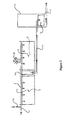
In FIG. 2, the construction of the fourth embodiment of the present invention is shown. The upper filter zone 3 and the lower filter zone 5 adjoin one another without a barrier layer 4. In this embodiment, flooding regulators, in particular valves and/or pumps, are provided, which ensure diverse and differing milieu conditions in the two filter zones 3, 5. Firstly, flooding is caused in the lower filter zone 5, whereby this filter zone is subjected to anaerobic milieu conditions. The upper filter zone is defined by an aerobic area, which is a function of the flooding boundary. The processes already explained above thus run in the individual filter zones 3, 5. In addition, in this embodiment a device 7 is included for admixing materials for improving the phosphate capacity.
LIST OF REFERENCE NUMERALS
    • inflow 1
    • distributor system 2
    • upper filter zone 3
    • barrier layer having openings at the edges 4
    • lower filter zone 5
    • device for introducing polluted water which has not been biologically treated into the lower filter zone 6
    • device for collecting and draining purified polluted water 7
    • seal 8
    • plants 9
    • device for admixing materials for improving the phosphate binding capacity 10 (first variant)
    • drain 11
    • device for phosphate retention 12 (second variant)
    • container, shaft, basin, inter alia 13
    • device 14 for diverse and differing milieu conditions in the filter zone 3, 5.
An array of advantages is achieved by the present invention, in particular a sudden improvement of the denitrification performance and/or the phosphate retention and/or the phosphate elimination.

Claims (16)

1. A vertical-horizontal filter unit for the biological purification of polluted water, comprising:
an upper filter zone (3) having feeds (1) for the polluted water,
a lower filter zone (5), situated beneath it,
a barrier layer (4) having opening(s), wherein the barrier layer (4) is situated between the upper and lower filter zones (3, 5),
and at least one removal location (7), the polluted water permeating the lower filter zone (5) after permeating the upper filter zone (3) and the filter unit having a seal (8) in relation to the soil on its sides and/or its floor, wherein
the filter unit comprises a device (6) for introducing a medium, which contains organic carbon, into the lower filter zone (5), or for introducing microorganisms and/or substances, which cause or support metabolism of the materials contained in the polluted water, into the lower filter zone (5),
the upper filter zone (3) is an aerobic filter zone, in which a nitrification of the polluted water occurs,
the lower filter zone (5) is an anaerobic filter zone, having denitrifying microorganisms, in which mixing and denitrification of the nitrified polluted water, which was treated in the upper filter zone (3), with a medium, which contains organic carbon, occurs, wherein the barrier layer (4) having opening(s) is situated between the upper and lower filter zones (3, 5),
the lower filter zone (3) and the upper filter zone (5) are homogeneous.
2. The filter unit according to claim 1, characterized by the following feature:
polluted water which is biologically untreated is introduced via the device (6).
3. The filter unit according to claim 1, characterized by the following feature:
methanolic acid or acetic acid is introduced via the device (6).
4. The filter unit according to claim 1, characterized by the following feature:
polluted water from compost production, wine and food processing or animal husbandry, and/or press water from biofermentation is introduced via the device (6).
5. The filter unit according to claim 1, characterized by the following feature:
organic substances, in particular fermentation residues or residues from animal husbandry, are introduced via the device (6).
6. The filter unit according to claim 1, characterized by the following feature:
the barrier layer (4) runs diagonally downward.
7. The filter unit according to claim 1, characterized by the following features:
the upper filter zone (3) has a least one removal device for biologically purified water,
a separately situated receptacle receives the biologically purified water and discharges it into the lower filter zone (5).
8. The filter unit according to claim 7, characterized by the following feature:
the receptacle has a unit for admixing the carbonaceous medium and/or an organic substance.
9. The filter unit according to claim 1, characterized by the following feature:
flooding regulators, valves and/or pumps, are situated in the upper and/or lower filter zones (3, 5).
10. The filter unit according to claim 1, characterized by the following feature:
filter bodies having higher phosphorous binding capacity are situated in the upper and/or lower filter zones (3, 5).
11. The filter unit according to claim 1, characterized by the following feature:
the microorganisms are genetically modified bacteria strains or yeast strains.
12. The vertical-horizontal filter unit of claim 1, wherein said upper filter zone (3) and/or said lower filter zone (5) comprises gravel or sand.
13. A method for polluted water purification by horizontal-vertical filtering, in which an upper filter zone is permeated with polluted water into a lower filter zone situated underneath, a barrier layer having opening(s) being situated between the upper and lower filter zones, a seal to the soil being produced at the sides and/or the floor, characterized in that a medium which contains organic carbon is introduced into the lower filter zone, and the upper filter zone is an aerobic zone, in which a nitrification of the polluted water occurs, and the lower filter zone is an anaerobic zone having denitrifying microorganisms, in which mixing and denitrification of the nitrified polluted water which was treated in the upper filter zone with a medium which contains organic carbon occurs, the lower filter zone and the upper filter zone being homogeneous, and microorganisms and/or substances which cause or support metabolism of the materials contained in the polluted water are supplied into the lower filter zone (5) via a device (6).
14. The method according to claim 13, characterized by the following feature:
different milieu conditions are caused by flooding in the upper filter zone and the lower filter zone.
15. The method according to claim 13, characterized by the following feature:
the lower filter zone is inoculated using microorganisms and/or metabolically-active substances.
16. The method of claim 13, wherein said upper filter zone (3) and/or said lower filter zone (5) comprises gravel or sand.
US12/516,154 2006-11-25 2007-11-23 Vertical-horizontal filter unit for the biological purification of polluted water Expired - Fee Related US8029673B2 (en)

Applications Claiming Priority (4)

Application Number Priority Date Filing Date Title
EP06024475.3 2006-11-25
EP06024475A EP1925598A1 (en) 2006-11-25 2006-11-25 Vertical-Horizontal Filtration device for the biological treatment of waste water
EP06024475 2006-11-25
PCT/EP2007/010202 WO2008061785A1 (en) 2006-11-25 2007-11-23 Vertical-horizontal filter unit for the biological purification of polluted water

Publications (2)

Publication Number Publication Date
US20100059438A1 US20100059438A1 (en) 2010-03-11
US8029673B2 true US8029673B2 (en) 2011-10-04

Family

ID=37913535

Family Applications (1)

Application Number Title Priority Date Filing Date
US12/516,154 Expired - Fee Related US8029673B2 (en) 2006-11-25 2007-11-23 Vertical-horizontal filter unit for the biological purification of polluted water

Country Status (3)

Country Link
US (1) US8029673B2 (en)
EP (2) EP1925598A1 (en)
WO (1) WO2008061785A1 (en)

Cited By (1)

* Cited by examiner, † Cited by third party
Publication number Priority date Publication date Assignee Title
US8894849B1 (en) * 2011-03-03 2014-11-25 The United States Of America As Represented By The Secretary Of The Air Force Upward flow constructed wetland for treatment of water contaminated with chlorinated aliphatics

Families Citing this family (11)

* Cited by examiner, † Cited by third party
Publication number Priority date Publication date Assignee Title
US8974664B2 (en) * 2011-01-24 2015-03-10 Ceres H2O Technologies, LLC Storm water treatment system
FR2974798B1 (en) * 2011-05-03 2014-06-13 Philippe Michel METHOD AND SYSTEM FOR TREATING EFFLUENTS
EP2716607B1 (en) * 2011-05-24 2019-11-13 Sung Il En-Tech Co. Ltd. Hybrid artificial wetland water purification system, sewage treatment device using same, and natural nonpoint purification device capable of simultaneously purifying river and lake water
DE102011080259A1 (en) * 2011-08-02 2013-02-07 Adolf Steinbach, Steinindustrie-Schotterwerke GmbH & Co KG Limestone sand filter material, in particular hard limestone, crushed quartz sand, production and use thereof for the purification of various waste waters
CN102874892A (en) * 2012-10-29 2013-01-16 周振民 Ecological cyclic treatment and utilization process of anaerobic waste solution in livestock and poultry farm
CN103130382B (en) * 2013-03-15 2014-06-11 重庆大学 Aeration biological filter-artificial wetland combination sewage low-carbon treatment reactor
US10807885B1 (en) * 2014-10-24 2020-10-20 Clean Water Services Low energy nitrogen removal wetland technology
US10144656B2 (en) 2015-08-07 2018-12-04 Kimball & Sons, Inc. Water filtration and purification system and method using activated charcoal and barley straw
CN108751418B (en) * 2018-06-29 2021-06-04 东华大学 Carbon source self-supply methane-producing type efficient denitrification horizontal subsurface flow constructed wetland
CN110790382A (en) * 2019-12-05 2020-02-14 吉康宁 Modularized micro-power equipment for treating rural domestic sewage and method thereof
CN112340838A (en) * 2020-11-06 2021-02-09 深圳市宇思环保科技有限公司 Filler, water treatment device and water treatment method

Citations (14)

* Cited by examiner, † Cited by third party
Publication number Priority date Publication date Assignee Title
CH671571A5 (en) * 1987-03-13 1989-09-15 Zentrum Fuer Angewandte Oekolo Filter bed for waste water treatment - planted with nitrophilic aquatic plants for denitrification and iron scrap for phosphate pptn.
DE4225699C1 (en) 1992-08-04 1994-01-20 Hermann Dipl Ing Rehnen Biological waste water purificn. - in layered clarification plant having compressed air and external organic carbon surface
DE4323610C1 (en) 1993-07-12 1995-02-09 Ingbuero Dr Fechter Gmbh Biopolder for the biological clean-up of soils and sludges
DE4422017A1 (en) * 1994-06-16 1995-05-11 Marion Dr Martienssen Process for stabilising the denitrification in biological sewage treatment plants by used motor vehicle radiator fluid
US5733453A (en) * 1996-07-15 1998-03-31 Azurea, Inc. Wastewater treatment system and method
DE19737690A1 (en) 1997-03-29 1998-10-01 Joachim Boettcher Small-scale water treatment plant combines reed bed and gravel filter
US5951866A (en) * 1996-07-31 1999-09-14 Grove; John E. Cold climate wetland waste water treatment system
US6406627B1 (en) * 1997-06-23 2002-06-18 North American Wetland Engineering, Inc. Method for removing pollutants from water
US6858142B2 (en) * 2000-09-13 2005-02-22 Rootzone Australia Pty Ltd. Polluted water treatment system
US6890439B2 (en) * 2000-05-22 2005-05-10 Dowmus Pty. Ltd. Biolytic filtration
US20050284811A1 (en) * 2004-06-28 2005-12-29 Potts David A Apparatus and method for wastewater treatment
US20060151387A1 (en) * 2004-12-06 2006-07-13 Russell Yost Multiple soil-layering system for wastewater purification
US20080197073A1 (en) * 2004-09-16 2008-08-21 Thierry Jacquet Treating Pollutants By Photoleaching
US7510649B1 (en) * 2004-01-09 2009-03-31 Ronald Lavigne Top loading vertical flow submerged bed wastewater treatment system

Patent Citations (14)

* Cited by examiner, † Cited by third party
Publication number Priority date Publication date Assignee Title
CH671571A5 (en) * 1987-03-13 1989-09-15 Zentrum Fuer Angewandte Oekolo Filter bed for waste water treatment - planted with nitrophilic aquatic plants for denitrification and iron scrap for phosphate pptn.
DE4225699C1 (en) 1992-08-04 1994-01-20 Hermann Dipl Ing Rehnen Biological waste water purificn. - in layered clarification plant having compressed air and external organic carbon surface
DE4323610C1 (en) 1993-07-12 1995-02-09 Ingbuero Dr Fechter Gmbh Biopolder for the biological clean-up of soils and sludges
DE4422017A1 (en) * 1994-06-16 1995-05-11 Marion Dr Martienssen Process for stabilising the denitrification in biological sewage treatment plants by used motor vehicle radiator fluid
US5733453A (en) * 1996-07-15 1998-03-31 Azurea, Inc. Wastewater treatment system and method
US5951866A (en) * 1996-07-31 1999-09-14 Grove; John E. Cold climate wetland waste water treatment system
DE19737690A1 (en) 1997-03-29 1998-10-01 Joachim Boettcher Small-scale water treatment plant combines reed bed and gravel filter
US6406627B1 (en) * 1997-06-23 2002-06-18 North American Wetland Engineering, Inc. Method for removing pollutants from water
US6890439B2 (en) * 2000-05-22 2005-05-10 Dowmus Pty. Ltd. Biolytic filtration
US6858142B2 (en) * 2000-09-13 2005-02-22 Rootzone Australia Pty Ltd. Polluted water treatment system
US7510649B1 (en) * 2004-01-09 2009-03-31 Ronald Lavigne Top loading vertical flow submerged bed wastewater treatment system
US20050284811A1 (en) * 2004-06-28 2005-12-29 Potts David A Apparatus and method for wastewater treatment
US20080197073A1 (en) * 2004-09-16 2008-08-21 Thierry Jacquet Treating Pollutants By Photoleaching
US20060151387A1 (en) * 2004-12-06 2006-07-13 Russell Yost Multiple soil-layering system for wastewater purification

Non-Patent Citations (3)

* Cited by examiner, † Cited by third party
Title
English Language International Preliminary Report on Patentability for International Application No. PCT/EP2007/010202, dated Jun. 10, 2009.
International Search Report for International Application No. PCT/EP2007/010202, mailed Mar. 27, 2008.
Written Opinion for International Application No. PCT/EP2007/010202, mailed Mar. 27, 2008.

Cited By (1)

* Cited by examiner, † Cited by third party
Publication number Priority date Publication date Assignee Title
US8894849B1 (en) * 2011-03-03 2014-11-25 The United States Of America As Represented By The Secretary Of The Air Force Upward flow constructed wetland for treatment of water contaminated with chlorinated aliphatics

Also Published As

Publication number Publication date
EP2102115A1 (en) 2009-09-23
EP1925598A1 (en) 2008-05-28
EP2102115B1 (en) 2014-08-20
US20100059438A1 (en) 2010-03-11
WO2008061785A1 (en) 2008-05-29

Similar Documents

Publication Publication Date Title
US8029673B2 (en) Vertical-horizontal filter unit for the biological purification of polluted water
US7790032B2 (en) Waste treatment process
US5951866A (en) Cold climate wetland waste water treatment system
US6126827A (en) High-strength septage biological treatment system
US5462666A (en) Treatment of nutrient-rich water
US5733453A (en) Wastewater treatment system and method
Samal et al. A comparative study of macrophytes influence on performance of hybrid vermifilter for dairy wastewater treatment
WO2004087584A1 (en) System and method for the treatment of wastewater using plants
Yildiz Water and wastewater treatment: Biological processes
KR101241817B1 (en) Treatment method of leachates from landfill and device thereof
US7128839B1 (en) Process and system for enhanced nitrogen removal in a wetland and recirculating sand filter wastewater treatment system
Minakshi et al. Performance evaluation of vertical constructed wetland units with hydraulic retention time as a variable operating factor
Farooqi et al. Constructed wetland system (CWS) for wastewater treatment
KR100453806B1 (en) High concentrated organic wastewater treatment apparatus and method thereof
KR100458202B1 (en) Waste Water Natural Disposal Apparatus with Maximized Efficiency and the method thereof
RU2406578C1 (en) Method of solid household refuses reclamation and polygon for their placement
Kinigopoulou et al. Utilization of biobed for the efficient treatment of olive oil mill wastewater
CN100506707C (en) Controlled biomembrane landscape wetland sewage purification system and technique
KR20010000303A (en) A Soil Clothing-Style Contact Oxidation Apparatus with Recycle of Nitrified Liquid and Contact Oxidation Method of Using the Same
Patel et al. Microbial ecology of biofiltration
Kettab et al. Urban wastewater treatment plants
Al-Rekabi et al. Performance of vertical flow constructed wetland for sewage treatment using different aquatic plants in the south of Iraq
Guyer et al. An Introduction to Advanced Wastewater Treatment
US20240101455A1 (en) Waste Water Treatment System
KR200310567Y1 (en) Waste Water Natural Disposal Apparatus with Maximized Efficiency

Legal Events

Date Code Title Description
STCF Information on status: patent grant

Free format text: PATENTED CASE

CC Certificate of correction
AS Assignment

Owner name: AREAL VERTRIEBS- UND SERVICE GMBH & CO. KG, GERMAN

Free format text: ASSIGNMENT OF ASSIGNORS INTEREST;ASSIGNOR:BOETTCHER, JOACHIM;REEL/FRAME:028057/0338

Effective date: 20120229

FEPP Fee payment procedure

Free format text: PAYOR NUMBER ASSIGNED (ORIGINAL EVENT CODE: ASPN); ENTITY STATUS OF PATENT OWNER: SMALL ENTITY

FPAY Fee payment

Year of fee payment: 4

FEPP Fee payment procedure

Free format text: MAINTENANCE FEE REMINDER MAILED (ORIGINAL EVENT CODE: REM.); ENTITY STATUS OF PATENT OWNER: SMALL ENTITY

LAPS Lapse for failure to pay maintenance fees

Free format text: PATENT EXPIRED FOR FAILURE TO PAY MAINTENANCE FEES (ORIGINAL EVENT CODE: EXP.); ENTITY STATUS OF PATENT OWNER: SMALL ENTITY

STCH Information on status: patent discontinuation

Free format text: PATENT EXPIRED DUE TO NONPAYMENT OF MAINTENANCE FEES UNDER 37 CFR 1.362

FP Lapsed due to failure to pay maintenance fee

Effective date: 20191004