US8029373B2 - Fixed constant velocity universal joint - Google Patents
Fixed constant velocity universal joint Download PDFInfo
- Publication number
- US8029373B2 US8029373B2 US12/084,324 US8432406A US8029373B2 US 8029373 B2 US8029373 B2 US 8029373B2 US 8432406 A US8432406 A US 8432406A US 8029373 B2 US8029373 B2 US 8029373B2
- Authority
- US
- United States
- Prior art keywords
- spherical surface
- track grooves
- cage
- axially extending
- inner ring
- Prior art date
- Legal status (The legal status is an assumption and is not a legal conclusion. Google has not performed a legal analysis and makes no representation as to the accuracy of the status listed.)
- Expired - Fee Related, expires
Links
- 238000010348 incorporation Methods 0.000 abstract description 6
- 238000000034 method Methods 0.000 description 12
- 238000003780 insertion Methods 0.000 description 9
- 230000037431 insertion Effects 0.000 description 9
- 238000007142 ring opening reaction Methods 0.000 description 8
- 238000010276 construction Methods 0.000 description 6
- 238000010586 diagram Methods 0.000 description 4
- 238000003754 machining Methods 0.000 description 4
- 238000006073 displacement reaction Methods 0.000 description 3
- 230000004323 axial length Effects 0.000 description 2
- 230000005540 biological transmission Effects 0.000 description 2
- 230000000694 effects Effects 0.000 description 2
- 238000011156 evaluation Methods 0.000 description 1
- 238000005242 forging Methods 0.000 description 1
- 230000001771 impaired effect Effects 0.000 description 1
- 230000002093 peripheral effect Effects 0.000 description 1
- 230000003068 static effect Effects 0.000 description 1
Images


Classifications
-
- F—MECHANICAL ENGINEERING; LIGHTING; HEATING; WEAPONS; BLASTING
- F16—ENGINEERING ELEMENTS AND UNITS; GENERAL MEASURES FOR PRODUCING AND MAINTAINING EFFECTIVE FUNCTIONING OF MACHINES OR INSTALLATIONS; THERMAL INSULATION IN GENERAL
- F16D—COUPLINGS FOR TRANSMITTING ROTATION; CLUTCHES; BRAKES
- F16D3/00—Yielding couplings, i.e. with means permitting movement between the connected parts during the drive
- F16D3/16—Universal joints in which flexibility is produced by means of pivots or sliding or rolling connecting parts
- F16D3/20—Universal joints in which flexibility is produced by means of pivots or sliding or rolling connecting parts one coupling part entering a sleeve of the other coupling part and connected thereto by sliding or rolling members
- F16D3/22—Universal joints in which flexibility is produced by means of pivots or sliding or rolling connecting parts one coupling part entering a sleeve of the other coupling part and connected thereto by sliding or rolling members the rolling members being balls, rollers, or the like, guided in grooves or sockets in both coupling parts
- F16D3/223—Universal joints in which flexibility is produced by means of pivots or sliding or rolling connecting parts one coupling part entering a sleeve of the other coupling part and connected thereto by sliding or rolling members the rolling members being balls, rollers, or the like, guided in grooves or sockets in both coupling parts the rolling members being guided in grooves in both coupling parts
- F16D3/2237—Universal joints in which flexibility is produced by means of pivots or sliding or rolling connecting parts one coupling part entering a sleeve of the other coupling part and connected thereto by sliding or rolling members the rolling members being balls, rollers, or the like, guided in grooves or sockets in both coupling parts the rolling members being guided in grooves in both coupling parts where the grooves are composed of radii and adjoining straight lines, i.e. undercut free [UF] type joints
-
- F—MECHANICAL ENGINEERING; LIGHTING; HEATING; WEAPONS; BLASTING
- F16—ENGINEERING ELEMENTS AND UNITS; GENERAL MEASURES FOR PRODUCING AND MAINTAINING EFFECTIVE FUNCTIONING OF MACHINES OR INSTALLATIONS; THERMAL INSULATION IN GENERAL
- F16D—COUPLINGS FOR TRANSMITTING ROTATION; CLUTCHES; BRAKES
- F16D3/00—Yielding couplings, i.e. with means permitting movement between the connected parts during the drive
- F16D3/16—Universal joints in which flexibility is produced by means of pivots or sliding or rolling connecting parts
- F16D3/20—Universal joints in which flexibility is produced by means of pivots or sliding or rolling connecting parts one coupling part entering a sleeve of the other coupling part and connected thereto by sliding or rolling members
- F16D3/22—Universal joints in which flexibility is produced by means of pivots or sliding or rolling connecting parts one coupling part entering a sleeve of the other coupling part and connected thereto by sliding or rolling members the rolling members being balls, rollers, or the like, guided in grooves or sockets in both coupling parts
- F16D3/223—Universal joints in which flexibility is produced by means of pivots or sliding or rolling connecting parts one coupling part entering a sleeve of the other coupling part and connected thereto by sliding or rolling members the rolling members being balls, rollers, or the like, guided in grooves or sockets in both coupling parts the rolling members being guided in grooves in both coupling parts
-
- F—MECHANICAL ENGINEERING; LIGHTING; HEATING; WEAPONS; BLASTING
- F16—ENGINEERING ELEMENTS AND UNITS; GENERAL MEASURES FOR PRODUCING AND MAINTAINING EFFECTIVE FUNCTIONING OF MACHINES OR INSTALLATIONS; THERMAL INSULATION IN GENERAL
- F16D—COUPLINGS FOR TRANSMITTING ROTATION; CLUTCHES; BRAKES
- F16D2250/00—Manufacturing; Assembly
-
- F—MECHANICAL ENGINEERING; LIGHTING; HEATING; WEAPONS; BLASTING
- F16—ENGINEERING ELEMENTS AND UNITS; GENERAL MEASURES FOR PRODUCING AND MAINTAINING EFFECTIVE FUNCTIONING OF MACHINES OR INSTALLATIONS; THERMAL INSULATION IN GENERAL
- F16D—COUPLINGS FOR TRANSMITTING ROTATION; CLUTCHES; BRAKES
- F16D2300/00—Special features for couplings or clutches
- F16D2300/12—Mounting or assembling
-
- Y—GENERAL TAGGING OF NEW TECHNOLOGICAL DEVELOPMENTS; GENERAL TAGGING OF CROSS-SECTIONAL TECHNOLOGIES SPANNING OVER SEVERAL SECTIONS OF THE IPC; TECHNICAL SUBJECTS COVERED BY FORMER USPC CROSS-REFERENCE ART COLLECTIONS [XRACs] AND DIGESTS
- Y10—TECHNICAL SUBJECTS COVERED BY FORMER USPC
- Y10S—TECHNICAL SUBJECTS COVERED BY FORMER USPC CROSS-REFERENCE ART COLLECTIONS [XRACs] AND DIGESTS
- Y10S464/00—Rotary shafts, gudgeons, housings, and flexible couplings for rotary shafts
- Y10S464/904—Homokinetic coupling
- Y10S464/906—Torque transmitted via radially spaced balls
Definitions
- the present invention relates to a fixed constant velocity universal joint, and more specifically, to a fixed constant velocity universal joint which is used in the power transmitting system of automobiles and various industrial machines and which solely allows angular displacement between two shafts on the driving side and the driven side.
- a fixed constant velocity universal joint is an example of a constant velocity universal joint used as a means for transmitting torque from the engine of an automobile to the wheels at constant velocity.
- the fixed constant velocity universal joint connects two shafts on the driving side and the driven side and is equipped with a structure allowing constant-velocity transmission of rotational torque even when the two shafts assume an operating angle.
- a fixed constant velocity universal joint is equipped with an outer ring serving as an outer member having a plurality of track grooves formed in an inner spherical surface thereof at equal circumferential intervals so as to extend in the axial direction, an inner ring serving as an inner member having a plurality of track grooves paired with the track grooves of the outer ring and formed in an outer spherical surface thereof at equal circumferential intervals so as to extend in the axial direction, a plurality of balls interposed between the track grooves of the outer ring and the track grooves of the inner ring, for transmitting torque, and a cage interposed between the inner spherical surface of the outer ring and the outer spherical surface of the inner ring, for holding the balls.
- the plurality of balls are accommodated in a pocket formed in the cage and are arranged at equal circumferential intervals (see, for example, JP 53-48150 A, DE 19514868, JP 08-6758 B, and JP 09-177810 A
- a constant velocity universal joint of this type When a constant velocity universal joint of this type is used, for example, for an automotive drive shaft, the outer ring is connected to a driven shaft, and a drive shaft extending from a slide type constant velocity universal joint mounted to a differential on the vehicle body side is connected to the inner ring through spline fit-engagement.
- a constant velocity universal joint when an operating angle is assumed between the outer ring and the inner ring, each of the balls accommodated in the cage is always maintained within the bisector plane of any operating angle, thereby securing the constant velocity property of the joint.
- a method is available according to which a distance d between a boundary portion between one track groove 7 and the outer spherical surface 6 of an inner ring 8 and a boundary portion between the opposing track groove 7 and the outer spherical surface 6 is previously set smaller than a socket diameter D of a cage 10 ; when incorporating the inner ring 8 into the cage 10 , the inner ring 8 is inserted straight into the cage 10 via a socket portion 15 while rotated by 90° around the Y-axis, and then the inner ring 8 is rotated by 90° around the Y-axis to match the axis of the inner ring 8 with the axis of the cage 10 , thereby arranging the inner ring in a normal attitude.
- JP 53-48150 A discloses a method in which the joint opening side portion of the outer spherical surface of the inner ring is cut off, and in which the inner ring is inserted into the cage while being rotated by 90° around the Y-axis to fit the outer spherical surface of the inner ring into the pocket of the cage; then, the inner ring is rotated by 90° around the Y-axis to match the axis of the inner ring with the axis of the cage, thus arranging the inner ring in normal attitude.
- phase means a circumferential position of any of a plurality of outer spherical surface portions defined by the track grooves.
- JP 08-6758 B discloses a method in which the boundary portions between the outer spherical surface of the inner ring and the track grooves thereof are chamfered, and in which the chamfered portions of a part of the phases are made larger than the chamfered portions of the other phases, whereby, after inserting the inner ring into the cage straight via the socket portion of the cage while rotating the inner ring by 90° around the Y-axis, the inner ring is rotated by 90° around the Y-axis to match the axis of the inner ring with the axis of the cage, thereby arranging the inner ring in a normal attitude.
- JP 09-177810 A discloses a method in which the distance d between a boundary portion between one track groove 7 and the outer spherical surface 6 of the inner ring 8 and the boundary portion between the opposing track groove 7 and the outer spherical surface 6 is previously set smaller than the socket diameter D of the cage 10 (see FIGS.
- the present invention relates to a fixed constant velocity universal joint including: an outer member having in an inner spherical surface thereof a plurality of track grooves arranged at equal circumferential intervals and extending axially toward an opening; an inner member having in an outer spherical surface thereof a plurality of axially extending track grooves paired with the track grooves of the outer member and arranged at equal circumferential intervals; a plurality of balls interposed between the track grooves of the outer member and the track grooves of the inner member, for transmitting torque; and a cage interposed between the inner spherical surface of the outer member and the outer spherical surface of the inner member, for holding the balls, in which an outer member opening side portion of the outer spherical surface of the inner member is cut off, with a boundary portion between the cutoff portion and the outer spherical surface being rounded.
- the outer member opening side portion of the outer spherical surface of the inner member is cut off.
- boundary portion between the above-mentioned cutoff portion and the outer spherical surface is rounded, whereby even when a tensile load is exerted in the axial direction of the joint, it is possible to prevent the boundary portion between the cutoff portion and the outer spherical surface from being engaged in the inner spherical surface of the cage.
- socket portion implies each of the axial end openings of the inner spherical surface of the cage, allowing easy insertion of the inner member into the cage when incorporating the inner member into the cage.
- the track grooves of the outer member and the inner member are tapered, whereby an increase in operating angle is easily realized without involving an increase in the outer diameter of the outer member.
- the influence and tendency due to the tapering of the track grooves were examined with respect to the inner elements of the constant velocity universal joint, with the result that the upper limit value of the tapering angle of the track grooves was decided on 12° as the optimum value thereof.
- the applicant of the present invention conducted examination by static inner force analysis and finite element method (FEM) analysis while securing the requisite strength and durability, which constitute the conventional required basic performance, narrowing down the range of the tapering angle of the track grooves to set an optimum range thereof. Further, the evaluation results of samples with different tapering angles were checked for consistency with the analysis results.
- FEM finite element method
- the outer member opening side portion of the outer spherical surface of the inner member is cut off.
- the contour of the inner member that is, the outer spherical surface of the inner member, is contained so as to avoid interference with the socket portion of the cage in all phases, so linear insertion of the inner member via the socket portion of the cage is facilitated.
- the boundary portion between the cutoff portion and the outer spherical surface is rounded, whereby, even when a tensile load is exerted in the axial direction of the joint, it is possible to prevent the boundary portion between the cutoff portion and the outer spherical surface from being engaged in the inner spherical surface of the cage.
- the inner member can be linearly inserted into the socket portion of the cage without impairing the function of the joint, enabling the inner member to be easily incorporated into the cage.
- this effect is conspicuous in a tapered, high-angle constant velocity universal joint in which the track grooves of the outer member are linearly diverged toward the opening.
- FIG. 1 a is a sectional view of an inner ring showing a fixed constant velocity universal joint according to an embodiment of the present invention.
- FIG. 1 b is an enlarged portion of FIG. 1 a.
- FIG. 1 c is a right-hand side view of FIG. 1 a.
- FIG. 2 is a sectional view of the general construction of the fixed constant velocity universal joint according to the embodiment of the present invention.
- FIG. 3 a is a diagram showing a state prior to insertion of the inner ring into a cage according to the embodiment of the present invention.
- FIG. 3 b is a side view in section of the inner ring of 3 a.
- FIG. 4 is a diagram showing a state after the insertion of the inner ring into the cage according to the embodiment of the present invention.
- FIG. 5 a is a sectional view showing an example of a boundary portion between a cutoff portion and an outer spherical surface according to another embodiment of the present invention.
- FIG. 5 b is an enlarged portion of FIG. 5 a.
- FIG. 6 a is a sectional view showing another example of the boundary portion between the cutoff portion and the outer spherical surface according to another embodiment of the present invention.
- FIG. 6 b is an enlarged portion of FIG. 6 a.
- FIG. 7 is a sectional view showing an inner ring, in which chamfered portions are provided at boundary portions between the outer spherical surface and track grooves according to another embodiment of the present invention.
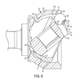
- FIG. 8 is a sectional view showing a state in which the fixed constant velocity universal joint assumes an operating angle according to the embodiment of the present invention.
- FIG. 9 a is a diagram showing a conventional fixed constant velocity universal joint in a state prior to insertion of an inner ring into a cage.
- FIG. 9 b is an enlarged portion of FIG. 9 a.
- FIG. 10 is a diagram showing the conventional fixed constant velocity universal joint in a state after the insertion of the inner ring into the cage.
- FIG. 2 shows a constant velocity universal joint according to an embodiment, which is equipped with an outer ring 25 serving as a cup-shaped outer member having in an inner spherical surface 21 thereof, a plurality of track grooves 22 arranged at equal circumferential intervals and extending in the axial direction toward an opening end 23 , an inner ring 28 serving as an inner member having in an outer spherical surface 26 , thereof a plurality of track grooves 27 paired with the track grooves 22 of the outer ring 25 and formed axially at equal circumferential intervals, a plurality of balls 29 interposed between the track grooves 22 of the outer ring 25 and the track grooves 27 of the inner ring 28 , for transmitting torque, and a cage 30 interposed between the inner spherical surface 21 of the outer ring 25 and the outer spherical surface 26 of the inner ring 28 , for holding the balls 29 .
- the plurality of balls 29 are accommodated in a pocket 24 formed in the cage 30 and arranged at equal circum
- a driven shaft (not shown) is connected to a stem portion extending integrally from the outer ring 25
- a drive shaft (not shown) is connected to the inner ring 28 through spline fit-engagement, whereby torque transmission is possible while allowing angular displacement between the driven shaft and the drive shaft.
- the track grooves 22 of the outer ring 25 are tapered so as to be linearly diverged toward the cup-shaped opening of the outer ring 25 . That is, the track grooves 22 have arcuate bottoms 22 a on the cup-shape bottom side, which is on the side opposite to the opening, and tapered bottoms 22 b on the cup-shape opening side.
- the track grooves 27 of the inner ring 28 are also tapered so as to be linearly diverged toward the side opposite to the cup-shaped opening of the outer ring 25 . That is, the track grooves 27 have arcuate bottoms 27 a on the cup-shape opening side and tapered bottoms 27 b on the cup-shape bottom side.
- a center of curvature O 3 of an inner spherical surface 31 of the cage 30 , and a center of curvature O 4 of an outer spherical surface 32 thereof, are axially offset in opposite directions by the same distance f with respect to a joint center plane P passing the joint center O (cage offset).
- a center of curvature O 1 of the track grooves 22 of the outer ring 25 and a center of curvature O 2 of the track grooves 27 of the inner ring 28 respectively match the center of curvature of the inner spherical surface 21 of the outer ring 25 and the center of curvature of the outer spherical surface 26 of the inner ring 28 .
- the center of curvature of the inner spherical surface 21 of the outer ring 25 and the center of curvature of the outer spherical surface 26 of the inner ring 28 respectively match the center of curvature O 4 of the outer spherical surface 32 of the cage 30 and the center of curvature O 3 of the inner spherical surface 31 thereof.
- the center of curvature of the inner spherical surface 21 of the outer ring 25 will also be indicated by symbol O 4
- the center of curvature of the outer spherical surface 26 of the inner ring 28 will also be indicated by symbol O 3 .
- the center of curvature O 1 of the track grooves 22 of the outer ring 25 and the center of curvature O 2 of the track grooves 27 of the inner ring 28 respectively match the center of curvature O 4 of the inner spherical surface 21 of the outer ring 25 and the center of curvature O 3 of the outer spherical surface 26 of the inner ring 28 to thereby reduce the track offset to zero.
- the depth of the arcuate bottoms 22 a situated on the inner side of the outer ring 25 is not reduced toward the inner side but is of a uniform depth, so, when an operating angle is assumed, it is possible to suppress running-on of the balls 29 situated at the innermost positions of the track grooves 22 .
- the center of curvature O 1 of the track grooves 22 of the outer ring 25 and the center of curvature O 2 of the track grooves 27 of the inner ring 28 may be respectively axially offset in opposite directions by the same distance with respect to the center of curvature O 4 of the inner spherical surface 21 of the outer ring 25 and the center of curvature O 3 of the outer spherical surface 26 of the inner ring 28 , to thereby effect track offset.
- the distance d between the boundary portion between one track groove 27 and the outer spherical surface 26 and the boundary portion between the opposing track groove 27 and the outer spherical surface 26 is previously set smaller than the socket diameter D of the cage 30 ; when incorporating the inner ring 28 into the cage 30 , the inner ring 28 is inserted into the cage 30 while being rotated by 90° around the Y-axis (see FIGS.
- the inner ring 28 is rotated by 90° around the Y-axis to match the axis of the inner ring 28 with the axis of the cage 30 , thereby arranging the inner ring in normal attitude.
- the outer ring opening side portion of the outer spherical surface 26 of the inner ring 28 is cut off in all phases, and the boundary portion 34 between the cutoff portion 33 and the outer spherical surface 26 is rounded.
- the outer ring opening side portion of the outer spherical surface 26 of the inner ring 28 is cut off, whereby, at the time of incorporation of the inner ring 28 into the cage 30 , when inserting the inner ring 28 into the cage 30 via a socket portion 35 of the cage 30 , the inner ring 28 is, as shown in FIG. 4 , contained within the region of the socket portion 35 so as to avoid interference of the contour of the inner ring 28 , that is, the outer ring bottom side portion (portion B in the drawing) of the outer spherical surface 26 , so the inner ring 28 can be linearly inserted via the socket portion 35 of the cage 30 .
- the portion where firm contact between the inner ring 28 and the cage 30 occurs during operation of the joint of the present invention is the outer ring bottom side portion of the outer spherical surface 26 of the inner ring 28 , and the outer ring opening side portion of the outer spherical surface 26 is not held in firm contact. Further, a sufficient depth can be secured on the outer ring opening side of the track grooves 27 of the inner ring 28 even when the above-mentioned cutoff portion 33 is provided, so the function of the joint is not affected.
- the track grooves 27 and 22 of the inner ring 28 and the outer ring 25 are axially elongated; in this case, the axial width of the inner ring 28 and that of the outer ring 25 are increased; however, when the axial width of the inner ring 28 is increased, by cutting off the outer ring opening side portion of the outer spherical surface 26 of the inner ring 28 as described above, at the time of incorporation of the inner ring 28 into the cage 30 , the contour of the inner ring 28 , that is, the outer ring bottom side portion and the outer ring opening side portion of the inner ring 28 and the outer spherical surface 26 , can be easily contained within the region of the socket portion 35 so that they may not interfere with the socket portion 35 of the cage 30 in all phases.
- the cutoff portion 33 provided on the outer ring opening side of the outer spherical surface 26 of the inner ring 28 is formed with respect to all phases of the outer spherical surface 26 , so, as compared with the case in which the cutoff portion 33 is provided solely with respect to a part of the phases (see, for example, Patent Document 2), the inner ring 28 can be machined more easily through turning, the load is more uniformly applied to the die during forging to provide superior workability, and a reduction in the weight of the inner ring 28 can be achieved. Further, the contact between the inner ring 28 and the cage 30 is uniform in all phases, so there is advantageously no variation in contact from phase to phase.
- the boundary portion 34 between the cutoff portion 33 of the inner ring 28 and the outer peripheral surface 26 thereof may be engaged in the inner spherical surface 31 of the cage 30 ; however, as stated above, the boundary portion 34 between the cutoff portion 33 of the inner ring 28 and the outer spherical surface 26 thereof is rounded, whereby, when a tensile load is applied in the axial direction of the joint, it is possible to prevent in advance the boundary portion 34 between the cutoff portion 33 of the inner ring 28 and the outer spherical surface 26 thereof from being engaged in the inner spherical surface 31 of the cage 30 .
- the cutoff portion 33 is of a conical configuration, this is to be construed as a mere example; the configuration of the cutoff portion 33 may be one other than a conical surface as long as the function of the joint is not impaired, and the contour of the outer spherical surface 26 of the inner ring 28 is contained so as to avoid interference with the socket portion 35 of the cage 30 .
- various methods are available, including turning and forge finishing.
- the rounded configuration of the boundary portion 34 between the cutoff portion 33 and the outer spherical surface 26 is one connected to both the cutoff portion 33 and the outer spherical surface 26 at a tangent
- the boundary portion 34 between the cutoff portion 33 and the outer spherical surface 26 is rounded, and, at the time of the finishing, machining is performed such that the outer spherical surface 26 exhibits a rounded finished configuration, whereby, although, strictly speaking, an edge Y appears between the finished configuration of the outer spherical surface 26 and the boundary portion 34 , the angle therebetween becomes obtuse, so it can be formed into a configuration that is not easily allowed to be engaged in the inner spherical surface 31 of the cage 30 .
- various methods are available, including forge finishing, turning, grinding, shot, and tumbling.
- the outer ring opening side portion of the outer spherical surface 26 of the inner ring 28 is cut off, and the boundary portion 34 between the cutoff portion 33 and the outer spherical surface 26 is rounded; in addition to this construction.
- the chamfered portions 36 are formed at all the boundary portions between the outer spherical surface 26 and the track grooves 27 of the inner ring 28 .
- the track grooves 22 and 27 of the outer ring 25 and the inner ring 28 are tapered, whereby an increase in operating angle is easily realized without involving an increase in the outer diameter of the outer ring 25 ; in this regard, in order that the strength and workability of the outer ring 25 may not be reduced even when the wall thickness of the outer ring 25 is reduced, the influence and tendency of the inner force consisting of the track load, pocket load, and spherical force was examined with respect to the inner elements of the fixed constant velocity universal joint, and finite element method (FEM) analysis was performed, with the result that the range of the tapering angle ⁇ of the track grooves 22 and 27 was narrowed down, the upper limit value thereof being decided on 12° as the optimum value.
- FEM finite element method
- the track grooves 22 of the outer ring 25 are of the tapered shape so as to be diverged linearly toward the opening end 23
- the track grooves 27 of the inner ring 28 are of the tapered shape so as to be diverged linearly toward an end on the opposite side of the opening
- the outer spherical surface center and the inner spherical surface center of the cage 30 are axially offset in opposite directions by the same distance from the joint center
- the center of curvature of the track grooves 22 of the outer ring 25 and the center of curvature of the track grooves 27 of the inner ring 28 are offset by the cage offset amount with respect to the joint center, whereby a high-angle structure is realized for a constant velocity universal joint
- the present invention is not restricted to the above-mentioned construction; it is also applicable to other fixed constant velocity universal joints (e.g., BJ and UJ).
Landscapes
- Engineering & Computer Science (AREA)
- General Engineering & Computer Science (AREA)
- Mechanical Engineering (AREA)
- Rolling Contact Bearings (AREA)
Abstract
Description
Claims (6)
Applications Claiming Priority (4)
| Application Number | Priority Date | Filing Date | Title |
|---|---|---|---|
| JP2005-334586 | 2005-11-18 | ||
| JP2005334586A JP4959177B2 (en) | 2005-11-18 | 2005-11-18 | Fixed constant velocity universal joint |
| JP2005334586 | 2005-11-18 | ||
| PCT/JP2006/322742 WO2007058201A1 (en) | 2005-11-18 | 2006-11-15 | Fixed constant velocity universal joint |
Publications (2)
| Publication Number | Publication Date |
|---|---|
| US20090258716A1 US20090258716A1 (en) | 2009-10-15 |
| US8029373B2 true US8029373B2 (en) | 2011-10-04 |
Family
ID=38048586
Family Applications (1)
| Application Number | Title | Priority Date | Filing Date |
|---|---|---|---|
| US12/084,324 Expired - Fee Related US8029373B2 (en) | 2005-11-18 | 2006-11-15 | Fixed constant velocity universal joint |
Country Status (5)
| Country | Link |
|---|---|
| US (1) | US8029373B2 (en) |
| EP (1) | EP1950437B1 (en) |
| JP (1) | JP4959177B2 (en) |
| CN (1) | CN101313159B (en) |
| WO (1) | WO2007058201A1 (en) |
Cited By (1)
| Publication number | Priority date | Publication date | Assignee | Title |
|---|---|---|---|---|
| US12535108B2 (en) | 2021-02-18 | 2026-01-27 | Jtekt Corporation | Constant velocity universal joint and manufacturing method of constant velocity universal joint |
Families Citing this family (2)
| Publication number | Priority date | Publication date | Assignee | Title |
|---|---|---|---|---|
| JP5143453B2 (en) * | 2007-03-20 | 2013-02-13 | Ntn株式会社 | Constant velocity universal joint |
| JP2019100459A (en) * | 2017-12-04 | 2019-06-24 | 本田技研工業株式会社 | Fixed constant velocity joint |
Citations (17)
| Publication number | Priority date | Publication date | Assignee | Title |
|---|---|---|---|---|
| US3879960A (en) | 1972-10-27 | 1975-04-29 | Loehr & Bromkamp Gmbh | Constant velocity joint |
| JPS5348150A (en) | 1976-08-11 | 1978-05-01 | Loehr & Bromkamp Gmbh | Synchronously rotaty coupling |
| GB2036255A (en) | 1978-12-04 | 1980-06-25 | Ntn Toyo Bearing Co Ltd | Constant velocity joint |
| GB2127132A (en) | 1982-09-11 | 1984-04-04 | Sobhy Labib Girguis | Universal joints |
| JPS60249728A (en) | 1984-05-25 | 1985-12-10 | Nippon Seiko Kk | Equi-speed joint |
| WO1992014943A1 (en) | 1991-02-21 | 1992-09-03 | Gkn Automotive Inc. | Constant velocity universal joint and method for making same |
| JPH086758A (en) | 1994-06-23 | 1996-01-12 | Matsushita Electric Ind Co Ltd | Image display memory access device |
| DE19514868C1 (en) | 1995-04-22 | 1996-05-23 | Loehr & Bromkamp Gmbh | Ball=type constant=velocity universal joint |
| JPH09177810A (en) | 1995-12-28 | 1997-07-11 | Ntn Corp | Cage for constant velocity universal joint and assembling method thereof |
| JP2000154833A (en) | 1998-11-19 | 2000-06-06 | Toyoda Mach Works Ltd | Constant velocity universal joint |
| JP2000230568A (en) | 1999-02-15 | 2000-08-22 | Toyoda Mach Works Ltd | Ball type constant velocity joint |
| JP2001304282A (en) | 2000-04-27 | 2001-10-31 | Ntn Corp | Fixing type constant velocity universal joint |
| US6431988B1 (en) | 1999-09-17 | 2002-08-13 | Ntn Corporation | Fixed type constant velocity joint and assembling method therefor |
| JP2005106233A (en) | 2003-10-01 | 2005-04-21 | Ntn Corp | Fixed type constant velocity universal joint |
| JP2005221033A (en) | 2004-02-06 | 2005-08-18 | Ntn Corp | Fixed type constant velocity universal joint |
| EP1669622A1 (en) | 2003-10-01 | 2006-06-14 | Ntn Corporation | Fixed type constant velocity universal joint |
| US20060217207A1 (en) * | 2005-03-22 | 2006-09-28 | Manabu Hoshino | Fixed-type constant-velocity universal joint |
-
2005
- 2005-11-18 JP JP2005334586A patent/JP4959177B2/en not_active Expired - Lifetime
-
2006
- 2006-11-15 US US12/084,324 patent/US8029373B2/en not_active Expired - Fee Related
- 2006-11-15 CN CN200680043142.XA patent/CN101313159B/en not_active Expired - Fee Related
- 2006-11-15 EP EP06832673A patent/EP1950437B1/en not_active Not-in-force
- 2006-11-15 WO PCT/JP2006/322742 patent/WO2007058201A1/en not_active Ceased
Patent Citations (22)
| Publication number | Priority date | Publication date | Assignee | Title |
|---|---|---|---|---|
| US3879960A (en) | 1972-10-27 | 1975-04-29 | Loehr & Bromkamp Gmbh | Constant velocity joint |
| JPS5348150A (en) | 1976-08-11 | 1978-05-01 | Loehr & Bromkamp Gmbh | Synchronously rotaty coupling |
| US4156353A (en) | 1976-08-11 | 1979-05-29 | Lohr & Bromkamp Gmbh | Homokinetic joint assembly |
| GB2036255A (en) | 1978-12-04 | 1980-06-25 | Ntn Toyo Bearing Co Ltd | Constant velocity joint |
| US4319465A (en) | 1978-12-04 | 1982-03-16 | Ntn Toyo Bearing Company, Ltd. | Constant velocity joint |
| GB2127132A (en) | 1982-09-11 | 1984-04-04 | Sobhy Labib Girguis | Universal joints |
| US4575362A (en) | 1982-09-11 | 1986-03-11 | Girguis Sobhy Labib | Constant velocity joint |
| US4820240A (en) | 1982-09-11 | 1989-04-11 | Girguis Sobhy Labib | Constant velocity joint |
| JPS60249728A (en) | 1984-05-25 | 1985-12-10 | Nippon Seiko Kk | Equi-speed joint |
| US5167584A (en) | 1991-02-21 | 1992-12-01 | Gkn Automotive, Inc. | Constant velocity universal joint and a method for making same |
| WO1992014943A1 (en) | 1991-02-21 | 1992-09-03 | Gkn Automotive Inc. | Constant velocity universal joint and method for making same |
| JPH086758A (en) | 1994-06-23 | 1996-01-12 | Matsushita Electric Ind Co Ltd | Image display memory access device |
| DE19514868C1 (en) | 1995-04-22 | 1996-05-23 | Loehr & Bromkamp Gmbh | Ball=type constant=velocity universal joint |
| JPH09177810A (en) | 1995-12-28 | 1997-07-11 | Ntn Corp | Cage for constant velocity universal joint and assembling method thereof |
| JP2000154833A (en) | 1998-11-19 | 2000-06-06 | Toyoda Mach Works Ltd | Constant velocity universal joint |
| JP2000230568A (en) | 1999-02-15 | 2000-08-22 | Toyoda Mach Works Ltd | Ball type constant velocity joint |
| US6431988B1 (en) | 1999-09-17 | 2002-08-13 | Ntn Corporation | Fixed type constant velocity joint and assembling method therefor |
| JP2001304282A (en) | 2000-04-27 | 2001-10-31 | Ntn Corp | Fixing type constant velocity universal joint |
| JP2005106233A (en) | 2003-10-01 | 2005-04-21 | Ntn Corp | Fixed type constant velocity universal joint |
| EP1669622A1 (en) | 2003-10-01 | 2006-06-14 | Ntn Corporation | Fixed type constant velocity universal joint |
| JP2005221033A (en) | 2004-02-06 | 2005-08-18 | Ntn Corp | Fixed type constant velocity universal joint |
| US20060217207A1 (en) * | 2005-03-22 | 2006-09-28 | Manabu Hoshino | Fixed-type constant-velocity universal joint |
Non-Patent Citations (3)
| Title |
|---|
| Graf Von Seherr-Thoss, Schmelz, Aucktor: "Gelenke and Gelenkwellen", 2002, Springer Verlag, Berlin, XP002564684, pp. 168-173. |
| International Search Report mailed Dec. 12, 2006 for International Application No. PCT/JP2006/322742. |
| Supplementary European Search Report dated Feb. 5, 2010 in corresponding European Application No. 06832673.5. |
Cited By (1)
| Publication number | Priority date | Publication date | Assignee | Title |
|---|---|---|---|---|
| US12535108B2 (en) | 2021-02-18 | 2026-01-27 | Jtekt Corporation | Constant velocity universal joint and manufacturing method of constant velocity universal joint |
Also Published As
| Publication number | Publication date |
|---|---|
| JP4959177B2 (en) | 2012-06-20 |
| EP1950437A1 (en) | 2008-07-30 |
| EP1950437B1 (en) | 2013-02-27 |
| US20090258716A1 (en) | 2009-10-15 |
| CN101313159B (en) | 2013-05-08 |
| CN101313159A (en) | 2008-11-26 |
| EP1950437A4 (en) | 2010-03-10 |
| JP2007139095A (en) | 2007-06-07 |
| WO2007058201A1 (en) | 2007-05-24 |
Similar Documents
| Publication | Publication Date | Title |
|---|---|---|
| US6120382A (en) | Constant velocity joint | |
| US20120165105A1 (en) | Fixed type constant velocity universal joint | |
| US6135891A (en) | Constant velocity universal joint | |
| JP2011112117A (en) | Stationary constant-velocity universal joint | |
| JP2012246952A (en) | Constant velocity universal joint | |
| EP2908020B1 (en) | Fixed-type constant-velocity universal joint | |
| EP1705395B1 (en) | Fixed-type constant-velocity universal joint | |
| US8510955B2 (en) | Inner joint part for a constant velocity universal joint and process of producing same | |
| KR101405073B1 (en) | Fixed constant velocity universal joint | |
| JP2000240673A (en) | Constant velocity universal joint for propeller shaft and propeller shaft | |
| WO2009145034A1 (en) | Fixed-type, constant-velocity universal joint | |
| EP2143964A1 (en) | Double-offset constant velocity universal joint | |
| US8029373B2 (en) | Fixed constant velocity universal joint | |
| US20110086714A1 (en) | Constant velocity joint | |
| US8342971B2 (en) | Fixed type constant velocity universal joint | |
| EP4394200A1 (en) | Plunging type constant velocity universal joint | |
| JP4879501B2 (en) | High angle fixed type constant velocity universal joint | |
| US7841948B2 (en) | Cross groove type constant velocity joint | |
| JP2024090755A (en) | Sliding constant velocity joint | |
| JP2010185538A (en) | Ball type constant velocity joint | |
| CN110446872B (en) | Drive shaft for rear wheel | |
| JP6711747B2 (en) | Fixed type constant velocity universal joint | |
| JP2000240678A (en) | Fixed type constant velocity universal joint | |
| JP5106968B2 (en) | Fixed constant velocity universal joint | |
| JP2010019344A (en) | Sliding type constant velocity universal joint |
Legal Events
| Date | Code | Title | Description |
|---|---|---|---|
| AS | Assignment |
Owner name: NTN CORPORATION, JAPAN Free format text: ASSIGNMENT OF ASSIGNORS INTEREST;ASSIGNORS:IZUMINO, JUNICHI;HOSHINO, MANABU;REEL/FRAME:020934/0191;SIGNING DATES FROM 20080408 TO 20080410 Owner name: NTN CORPORATION, JAPAN Free format text: ASSIGNMENT OF ASSIGNORS INTEREST;ASSIGNORS:IZUMINO, JUNICHI;HOSHINO, MANABU;SIGNING DATES FROM 20080408 TO 20080410;REEL/FRAME:020934/0191 |
|
| ZAAA | Notice of allowance and fees due |
Free format text: ORIGINAL CODE: NOA |
|
| ZAAB | Notice of allowance mailed |
Free format text: ORIGINAL CODE: MN/=. |
|
| STCF | Information on status: patent grant |
Free format text: PATENTED CASE |
|
| FPAY | Fee payment |
Year of fee payment: 4 |
|
| FEPP | Fee payment procedure |
Free format text: PAYOR NUMBER ASSIGNED (ORIGINAL EVENT CODE: ASPN); ENTITY STATUS OF PATENT OWNER: LARGE ENTITY |
|
| MAFP | Maintenance fee payment |
Free format text: PAYMENT OF MAINTENANCE FEE, 8TH YEAR, LARGE ENTITY (ORIGINAL EVENT CODE: M1552); ENTITY STATUS OF PATENT OWNER: LARGE ENTITY Year of fee payment: 8 |
|
| FEPP | Fee payment procedure |
Free format text: MAINTENANCE FEE REMINDER MAILED (ORIGINAL EVENT CODE: REM.); ENTITY STATUS OF PATENT OWNER: LARGE ENTITY |
|
| LAPS | Lapse for failure to pay maintenance fees |
Free format text: PATENT EXPIRED FOR FAILURE TO PAY MAINTENANCE FEES (ORIGINAL EVENT CODE: EXP.); ENTITY STATUS OF PATENT OWNER: LARGE ENTITY |
|
| STCH | Information on status: patent discontinuation |
Free format text: PATENT EXPIRED DUE TO NONPAYMENT OF MAINTENANCE FEES UNDER 37 CFR 1.362 |
|
| FP | Lapsed due to failure to pay maintenance fee |
Effective date: 20231004 |