US8028793B2 - Noise attenuating inserts for electronic equipment cabinets - Google Patents
Noise attenuating inserts for electronic equipment cabinets Download PDFInfo
- Publication number
- US8028793B2 US8028793B2 US12/563,513 US56351309A US8028793B2 US 8028793 B2 US8028793 B2 US 8028793B2 US 56351309 A US56351309 A US 56351309A US 8028793 B2 US8028793 B2 US 8028793B2
- Authority
- US
- United States
- Prior art keywords
- noise
- noise attenuating
- inserts
- cabinet
- frame extender
- Prior art date
- Legal status (The legal status is an assumption and is not a legal conclusion. Google has not performed a legal analysis and makes no representation as to the accuracy of the status listed.)
- Expired - Fee Related
Links
- 238000000034 method Methods 0.000 claims abstract description 16
- 239000004606 Fillers/Extenders Substances 0.000 claims description 82
- 239000000463 material Substances 0.000 claims description 20
- 238000001816 cooling Methods 0.000 description 15
- 239000006260 foam Substances 0.000 description 14
- 238000009826 distribution Methods 0.000 description 11
- OKTJSMMVPCPJKN-UHFFFAOYSA-N Carbon Chemical compound [C] OKTJSMMVPCPJKN-UHFFFAOYSA-N 0.000 description 10
- 229910002804 graphite Inorganic materials 0.000 description 10
- 239000010439 graphite Substances 0.000 description 10
- 230000000903 blocking effect Effects 0.000 description 5
- 238000009434 installation Methods 0.000 description 5
- 238000012423 maintenance Methods 0.000 description 4
- 239000011152 fibreglass Substances 0.000 description 3
- XLYOFNOQVPJJNP-UHFFFAOYSA-N water Substances O XLYOFNOQVPJJNP-UHFFFAOYSA-N 0.000 description 3
- 238000005516 engineering process Methods 0.000 description 2
- 238000012986 modification Methods 0.000 description 2
- 230000004048 modification Effects 0.000 description 2
- 229920000728 polyester Polymers 0.000 description 2
- 238000004064 recycling Methods 0.000 description 2
- 229920000877 Melamine resin Polymers 0.000 description 1
- 229920005830 Polyurethane Foam Polymers 0.000 description 1
- 239000011358 absorbing material Substances 0.000 description 1
- 238000009825 accumulation Methods 0.000 description 1
- 238000004378 air conditioning Methods 0.000 description 1
- 230000009286 beneficial effect Effects 0.000 description 1
- 230000005465 channeling Effects 0.000 description 1
- 230000001143 conditioned effect Effects 0.000 description 1
- 230000000593 degrading effect Effects 0.000 description 1
- 230000001627 detrimental effect Effects 0.000 description 1
- 238000005315 distribution function Methods 0.000 description 1
- 230000000694 effects Effects 0.000 description 1
- 230000007613 environmental effect Effects 0.000 description 1
- 238000004519 manufacturing process Methods 0.000 description 1
- JDSHMPZPIAZGSV-UHFFFAOYSA-N melamine Chemical compound NC1=NC(N)=NC(N)=N1 JDSHMPZPIAZGSV-UHFFFAOYSA-N 0.000 description 1
- 230000006855 networking Effects 0.000 description 1
- 239000004033 plastic Substances 0.000 description 1
- 229920003023 plastic Polymers 0.000 description 1
- 239000002574 poison Substances 0.000 description 1
- 231100000614 poison Toxicity 0.000 description 1
- 229920002635 polyurethane Polymers 0.000 description 1
- 239000004814 polyurethane Substances 0.000 description 1
- 239000011496 polyurethane foam Substances 0.000 description 1
- 238000005096 rolling process Methods 0.000 description 1
- 229940024463 silicone emollient and protective product Drugs 0.000 description 1
- 238000003466 welding Methods 0.000 description 1
Images


Classifications
-
- A—HUMAN NECESSITIES
- A47—FURNITURE; DOMESTIC ARTICLES OR APPLIANCES; COFFEE MILLS; SPICE MILLS; SUCTION CLEANERS IN GENERAL
- A47B—TABLES; DESKS; OFFICE FURNITURE; CABINETS; DRAWERS; GENERAL DETAILS OF FURNITURE
- A47B97/00—Furniture or accessories for furniture, not provided for in other groups of this subclass
-
- H—ELECTRICITY
- H05—ELECTRIC TECHNIQUES NOT OTHERWISE PROVIDED FOR
- H05K—PRINTED CIRCUITS; CASINGS OR CONSTRUCTIONAL DETAILS OF ELECTRIC APPARATUS; MANUFACTURE OF ASSEMBLAGES OF ELECTRICAL COMPONENTS
- H05K7/00—Constructional details common to different types of electric apparatus
- H05K7/20—Modifications to facilitate cooling, ventilating, or heating
- H05K7/20709—Modifications to facilitate cooling, ventilating, or heating for server racks or cabinets; for data centers, e.g. 19-inch computer racks
- H05K7/20718—Forced ventilation of a gaseous coolant
- H05K7/20736—Forced ventilation of a gaseous coolant within cabinets for removing heat from server blades
Abstract
A noise attenuating method, and a system thereof, for controlling acoustical noise in an electronic equipment enclosure is disclosed. The noise attenuating system includes one or more noise attenuating inserts configured to be removably attached to the electronic equipment enclosure so as to block noise from at least one electronic device contained in the electronic equipment enclosure and to channel an airflow from an inlet point to one or more outlet points of the electronic equipment enclosure. The method includes arranging one or more noise attenuating inserts within an electronic equipment enclosure such that the noise attenuating inserts simultaneously block noise from at least one electronic device contained in the enclosure and channel an airflow path circulating therein.
Description
The present invention relates to acoustical noise control, and more specifically, to a noise controlling system that includes one or more inserts of predetermined shapes made of acoustically absorptive materials for attenuating noise emitted from electronic devices in electronic equipment enclosures.
Noise and heat emitted from electronic components are two major issues that affect electronic equipment, particularly in the fields of computing and information technology (IT). Computing and IT equipment, including electronic devices such as general computers, mainframe servers, networking electronics, communications devices and the like, are generally enclosed in designated spaces such as IT rooms or closets, also referred to as data centers. In most instances, these devices are organized into what is known interchangeably as electronic equipment racks or frames. Electronic equipment racks are standardized enclosures having a front door and a back door designed for mounting multiple equipment modules. Each module is fixedly fastened to the rack. Depending on the specific application, a single electronic device (e.g. a server), or numerous ones, may be mounted onto each module. Several equipment racks adjacent to each other are typically arranged in rows in an enclosed data center. The recent advent of more powerful electronic devices in smaller sizes and higher power loads has resulted in data centers (or even individual racks) that generate large amounts of heat. Excessive heat negatively affects computing and IT equipment performance, reliability, life expectancy, and may even cause fatal failure. One solution for alleviating the accumulation of heat in conventional data centers has been to cool the electronic equipment by circulating cool air blown by fans and/or air conditioning units. The addition of these air moving devices generates acoustical noise (hereafter “noise”). Growing environmental concerns and recognition that lengthy and unprotected exposure to high levels of noise can be detrimental to people have resulted in strict requirements to reduce electronic equipment noise.
Conventional noise attenuating systems generally require large operating spaces. Since data center space is scarce and expensive, if users desire to enhance the cooling efficiency of electronic equipment enclosures such as racks in data centers, it can only be done at the expense of sacrificing acoustical solutions. For example, the installation of heat removing solutions such as a rear door heat exchanger or the like can only be done by eliminating an acoustical cover. Moreover, if noise attenuating solutions are needed in places where excessive noise exists, bulky noise reducing solutions (e.g., acoustical covers) may be impossible to be installed due to lack of space.
The various embodiments of the present invention address the foregoing problems by providing a noise attenuating method, and a system thereof, for controlling acoustical noise in an electronic equipment enclosure. The noise attenuating system includes one or more noise attenuating inserts configured to be removably attached to the electronic equipment enclosure so as to block acoustical noise from at least one electronic device contained in the electronic equipment enclosure and to channel an airflow from an inlet point to one or more outlet points of the electronic equipment enclosure such that the airflow is evenly distributed to the outlet points selectively channeled to predetermined electronic devices. The method includes arranging of the one or more noise attenuating inserts within an electronic equipment enclosure such that the noise attenuating inserts simultaneously block noise from at least one electronic device contained in the enclosure and channel an airflow path circulating therein.
In one embodiment, a system for controlling noise in an electronic equipment cabinet is disclosed. The noise attenuating system includes a frame extender attached to the electronic equipment cabinet and one or more noise attenuating inserts removably attached to the frame extender, each of the noise attenuating inserts is configured in a predetermined shape, when so configured the noise attenuating inserts simultaneously block noise from at least one electronic device contained in the electronic equipment cabinet and channel an airflow path within the frame extender. At least part of the one or more noise attenuating inserts is placed in the airflow path to channel the airflow path from a high velocity inlet point to a lower velocity outlet point.
In one embodiment, the one or more noise attenuating inserts are placed in a removable panel member, and the removable panel member is removably attached to the frame extender. In an alternate embodiment, the noise attenuation system also includes a door attached to the frame extender, and the removable panel member is attached to the door such that the attenuating inserts protrude into the frame extender.
In a further embodiment, the system includes a heat exchanger configured to cool air passing therein. In this embodiment, the frame extender and the one or more noise attenuating inserts are positioned between the electronic equipment cabinet and the heat exchanger.
In accordance with another embodiment, a cabinet for housing one or more electronic devices is disclosed. The cabinet includes a front door and a back door attached to the cabinet; a removable panel member configured to be removably attached to the cabinet; and one or more noise attenuating inserts selectively arranged in the removable panel member such that the noise attenuating inserts block noise from at least one electronic device contained in the cabinet and such that the noise attenuating inserts channel an airflow path within the cabinet. Each of the noise attenuating inserts is made of at least one of an acoustical foam, a fiberglass material and a graphite foam; and each of the noise attenuating inserts has a predetermined shape. In alternative embodiments, the noise attenuating inserts may be formed of any acoustically absorptive material.
In accordance to at least one embodiment of the present invention, a noise attenuating solution and improved cooling results may be readily obtained by a novel noise attenuating method for controlling noise in an electronic equipment cabinet. The noise attenuating method includes arranging one or more noise attenuating inserts in a removable panel member, the one or more noise attenuating inserts being configured to block noise from at least one electronic device contained in the cabinet and to channel an airflow path from an inlet point to one or more outlet points such that the airflow is evenly distributed to the outlet points or selectively channeled to predetermined electronic devices. Each of the noise attenuating inserts has a predetermined shape such that when at least one of the noise attenuating inserts is placed within the airflow path, the insert serves to channel the airflow path from an inlet point to one or more outlet points within the electronic equipment cabinet so as to improve cooling of electronic devices contained in the cabinet.
Other embodiments and advantages thereof may be readily inferred by those of ordinary skill in the art, by reading the detailed description of the disclosure in reference to the attached drawings.
The terminology used herein is for the purpose of describing particular embodiments only and is not intended to be limiting of the invention. As used herein, the singular forms “a”, “an” and “the” are intended to include the plural forms as well, unless the context clearly indicates otherwise. It will be further understood that the terms “comprises” and/or “comprising,” when used in this specification and claims, specify the presence of stated features, integers, steps, operations, elements, and/or components, but do not preclude the presence or addition of one or more other features, integers, steps, operations, elements, components, and/or groups thereof.
In the following description, reference is made to the accompanying drawings where like reference numerals refer to like parts throughout the disclosure. FIG. 1 illustrates one embodiment of a noise attenuating system 100 for controlling acoustical noise in an electronic equipment cabinet in accordance with the present invention. As used herein, the term “electronic equipment cabinet” is interchangeably referred to as a “rack”, “enclosure” and/or “frame”. In this embodiment, the noise attenuating system 100 for controlling noise in an electronic equipment cabinet or enclosure 110 includes one or more noise attenuating inserts arranged within enclosure 110. However, for ease of assembly and disassembly, the one or more noise attenuating inserts may be placed in an insert panel. In the embodiment of FIG. 1 , the one or more noise attenuating inserts are illustrated as being arranged in one or more panels 101, 102 and 103. Panels 101 to 103 are configured to be attached to enclosure 110. Preferably, the panels 101, 102 and 103 are also configured to be removable from enclosure 110 so as to allow access to electronic devices contained in the enclosure. Each of panels 101 to 103 contains therein a predetermined number of noise attenuating inserts or at least one noise attenuating insert; and each noise attenuating insert has a predetermined shape. The noise attenuating inserts are preferably placed within an airflow path so as to channel the airflow path from an inlet point to one or more outlet points so as to enhance cooing of electronic devices residing within the electronic equipment cabinet or enclosure 110.
In FIG. 1 , enclosure 110 may be part of the electronic equipment cabinet or may be a frame extender. Electronic equipment cabinets such as IT or computing racks most generally include a hinged front door and a hinged back door, and are typically configured to accommodate one or more electronic devices such as computers, servers, private branch exchangers (PBXs) or the like. There are many different types of racks readily available from manufactures nowadays. Typically, most of the racks are manufactured under specific industry standards, for example, the Electronics Industry Alliance (EIA) standard. Under these standards, the 19-inch rack format is often considered as the “standard” rack arrangement and is widely used to house electronic devices in telecommunications, computing, audio, entertainment and other industries. Accordingly, one example of enclosure 110 is a 19-inch rack (e.g., EIA™ 310-D) which is manufactured in accordance with the EIA standard. Another example of enclosure 110 may be of anyone of racks NetBAY42 Enterprise Rack, IBM S2 42U Rack or IBM S2 25U Rack, each of which is available from International Business Machines (IBM) of Armonk, N.Y., the assignee of the present application. Alternatively, enclosure 110 may be simply an extension of the electronic equipment cabinet or rack (also referred to as a “frame extender”) that is designed to be fixedly attached to the rack.
Frame extenders are accessories configured to be fixedly attached to racks. A frame extender may be required, for example, when the space available within a rack has been completely allocated to electronic devices and additional space is required for further installations. One instance in which a frame extender is typically required is when there is no space for cabling within the rack. In such an instance a structure with dimensions compatible to the dimensions to the rack can be attached to the front or back of the rack. One example of frame extender is part number M/T 7040-W42 frame extender, EMC skirts, and cable retainers for extended frames for Cluster 1600 pSeries High Performance Switch (HPS) available from IBM of Armonk, N.Y. The pSeries HPS switch only frame, for example is available with a four inch extender. The four inch extender can accommodate up to two pSeries HPS switches and their associated switch cables. However, if more than two switches are to be installed into the frame, the increased cable load requires a larger extender. Thus, as an example, a frame extender may be part number M/T 7040-W42 frame extender.
Referring back to FIG. 1 , enclosure 110 houses therein one or more panels 101, 102 and 103, each of which holds one or more noise attenuating inserts positioned in close proximity or adjacent to predetermined electronic devices (not shown). A rack cover 120 (shown open) is attached to enclosure 110, for example, via pivotable hinges 115 located on a side (right side in FIG. 1 ) of a front surface of enclosure 110. Alternatively, rack cover 120 may attached to enclosure 110 via other attaching means such as snap-on connectors, sliding guides, rolling casters, or the like. In yet other arrangements, rack cover 120 may not be attached at all, but simply placed very close (adjacent) to enclosure 110. Noise attenuating inserts 101 a and 101 b, each having a predetermined shape (e.g., each rectangular in this embodiment), have been arranged within a panel 101 (panel member). Similarly, noise attenuating insert 102 a having a predetermined shape (e.g., substantially square in this instance) has been arranged in a panel 102. Finally, noise attenuating inserts 103 a and 103 b each having a predetermined shape (both rectangular in FIG. 1 ) are arranged in panel 103.
Each of panels 101, 102 and 103 may be removably attached to enclosure 110, by using readily available fastening means (as described in more detail in reference to FIG. 2 below). For example, panels 101 and 102 are shown as being attached to enclosure 110 via fastening means 112(L) located on the left side of the front of enclosure 110, and fastening means 112(R) located on the right side of the front of enclosure 110. Alternatively, panel 103 is shown as being attached to enclosure 110 by fastening means 112 (B) located in the bottom of enclosure 110. Panel 103 holds attenuating inserts 103 a and 103 b strategically placed in an airflow path 125. Noise reducing inserts 103 a and 103 b are preferably so chosen and arranged to, for example, channel the air in the airflow path 125 to desired electronic devices (not shown) residing inside the enclosure 110 to thereby ensure a more efficient cooling effect. Alternatively, noise reducing inserts may channel airflow path 125 from a front section of the enclosure 110 to a back section (not shown) so as to redistribute the airflow path to create a desired airflow distribution. Preferably a desired airflow distribution may be one in which air from an inlet point is channeled to one or more outlet points, or a distribution in which air from the back of the rack is evenly distributed to a rear door heat exchanger (RDHx).
More specifically, as it is known to those skilled in the art, data centers typically circulate cool air at high-speed through cold aisles between rows of facing racks whereby the cool air enters the rack through predetermined inlets, and hot air exits through the back of the rack onto hot aisles. The RDHx feature is a water-cooled device that is mounted on the rear of the rack to actively cool the hot air exiting at back the rack. A supply hose delivers chilled and conditioned water to the heat exchanger. A return hose delivers warmed water back to a water pump or chiller. Each rear door heat exchanger may remove up to 50,000 British thermal units (BTUs) or approximately 15,000 watts of heat.
In such an environment, noise attenuating inserts 103 a and 103 b, for example, are preferably placed in the vicinity of an inlet point so as to redirect (channel) the airflow path passing through the inlet point and distribute the airflow into a desired airflow distribution. Alternatively, noise attenuating inserts may be placed at the back of the rack so as to channel an airflow path of hot air exiting at the back of the rack and to create an evenly distributed airflow to pass through a rear door heat exchanger. Examples of such airflow distributions are discussed in detail hereinbelow in reference to FIGS. 7 and 8 . Thus, the predetermined shapes of noise attenuating inserts serve to block noise emission from at least one electronic device, while simultaneously directing the airflow path to create a desired airflow distribution. Because in the arrangement of FIG. 1 the noise attenuating inserts are strategically placed so as to reduce noise of at least one electronic device arranged within enclosure 110 and to channel air from an airflow path, panels 101, 102 and 103 are considered to be in an operating position. In contrast, when the noise attenuating inserts are not in the operating position (e.g., when they are removed to allow access to components contained in the rack), panels 101, 102 and 103 are considered to be in a removed or non-operating position.
In the embodiment of FIG. 1 , the noise attenuating inserts are preferably made of readily available acoustical materials. The acoustical material of the noise attenuating inserts is not limited to any specific material. As long as the inserts can substantially attenuate any noise emanating from electronic devices residing within the rack, and as long as the attenuating inserts are designed in a modular manner such as building blocks of predetermined shapes, noise attenuating inserts can be made of any acoustically absorptive material. The term “modular” as used herein preferably means being designed or constructed with standardized units or dimensions allowing flexibility and variety in use. For example, a set of modules or modular parts allow flexibility in the way that they are combined. Some examples of acoustically absorptive materials suitable for creating modular building blocks of predetermined shapes are acoustical foam, fiberglass, graphite foam, or the like. However, as stated above, modular blocks of noise attenuating inserts may be manufactured of any acoustically absorptive material.
Acoustical foam panels, such as polyurethane polyester or melamine foam panels, are widely known and are typically used in audio recording studios. One example of a suitable sound absorbing material is PYRELL®, a polyester polyurethane foam material manufactured by the Silicone Products Division of General Electric and by Foamex International, Inc., a division of Trace International. This type of acoustical foam is also readily available under the trademark names of Sonex®, Ready Traps™, Soft Sound®, and Class A™ Acoustical Foam Panels. Fiberglass padding is also a well known noise attenuating material and has been used to passively attenuate noise emanating from computers. In recent years, high thermal conductivity graphite foams have been developed by Oak Ridge National Laboratory under the direction of the U.S. Department of Energy (DOE) Office of Transportation Technologies. The graphite foam is presently available from Poco Graphite Inc. under the trademark name of POCOFoam®. Graphite foam is very thin and made of highly oriented graphite. The graphite foams have been estimated to exhibit a thermal conductivity greater than 1700 W/m·K. Thus, for high-end electronic devices, heat/noise attenuating inserts made of graphite foam would be extremely beneficial.
It should be noted therefore that, in accordance with at least one embodiment, it is preferable that the noise attenuating inserts be modularly designed such that each insert has a predetermined shape, and that the predetermined shapes be easily combinable. Predetermined shapes may include specific geometrical shapes that can be combined to optimize noise attenuation and/or airflow distribution functions. For purposes of illustration, various examples of predetermined geometrical shapes are discussed throughout this specification. However, predetermined shapes are not limited to geometrical shapes alone. For example, predetermined shapes may also include more elaborate shapes, such aerodynamically curved shapes that may advantageously increase air moving efficiency. Modular blocks (preconfigured or predetermined shapes) of noise attenuating inserts can deliver more performance per floor space than traditional acoustical covers, in particular if thin acoustical materials are used. In addition, modular blocks of noise attenuating inserts can, for example, (1) be custom tailored to suit acoustical and/or cooling needs of specific devices or systems; (2) be reused across multiple systems, (3) eliminate concerns regarding the lifting weight of conventional acoustical covers, (4) facilitate recycling requirements, among others. Thus, it is considered that by providing the noise attenuation inserts in a variety of shapes such as rectangular, square, triangular, circular, semicircular, trapezoidal, hexagonal shapes or the like, the inserts may be made customizable to fit predetermined electronic devices to optimize the noise attenuating function, and/or can be made customizable to be placed in specific airflow paths to channel air into a desired flow. To that end, the noise attenuating inserts in predetermined shapes may be designed to conform to specific shapes or sizes of at least some of the most widely known electronic devices and/or equipment racks available in the market.
For example, particularly heat-sensitive and noise-generating electronic devices such as servers or uninterruptible power supply (UPS) systems may be targeted as high-end devices requiring specific noise attenuating inserts. Thus, a combination of predetermined shapes configured to satisfy specific acoustical and/or cooling requirements of high-end devices may be made available to consumers as a “premium” kit of parts. Cooling and/or acoustical needs of more generic components (e.g., rack mountable routers, switches, or the like) may be satisfied by selectively placing modular noise attenuating inserts in strategic locations in the vicinity of, or in contact with, a predetermined device so as attenuate noise and/or enhance cooling. Thus, noise attenuating inserts in a variety of shapes and sizes, preferably configured to fit a variety of generic electronic devices, may preferably be offered to consumers as a “generic” kit of parts. One of the advantages of providing modular noise attenuating inserts tailored for specific electronic devices is that the inserts may be easily placed either in the front or back door of electronic equipment cabinets (e.g., racks or frames) so as to channel air from an airflow path to those specific devices without causing airflow impedance. In addition, when noise attenuating inserts are arranged in panels (as shown in FIG. 1 ), the modularity of the inserts may greatly facilitate maintenance work and/or recycling initiatives by enabling replacement of only a predetermined insert (or panel) when the product reaches its lifecycle end.
Returning to the embodiment of FIG. 1 , as stated above, enclosure 110 may be part of the rack itself (where electronic devices are housed), or it may be a frame extender. A frame extender may be required in a case where the space within the rack has been completely allocated to electronic devices housed therein and no space is available to accommodate the attenuation inserts. Regardless of whether housing 110 is a rack or a frame extender, the attenuating inserts are either placed in insert panels, or directly attached to housing 110. For example, if highly efficient acoustical materials such as graphite foams are used to manufacture the inserts, such inserts may be easily accommodated within the rack itself. Alternatively, if no space is available within the rack, a frame extender should be preferably used to mount the noise attenuating inserts. Whether enclosure 110 is a frame extender or part of the rack itself, it is preferable that the attenuating inserts be mounted onto enclosure 110 in a manner that the inserts can be easily removed and replaced. It is even more preferable that attenuating inserts be removably mounted onto enclosure 110 by fasteners that can be removed without tools or with the minimum use of tools. Therefore, when access to electronic equipment is required, the noise attenuating inserts may be readily taken apart and replaced with ease. As general recommendation, it is preferable that the least number of different types of fasteners be used. Plastic or metallic fasteners may be equally suitable as long as the fasteners may be designed for repeated assembly and disassembly. One example of fasteners designed for repeated assembly and disassembly are snap fit fasteners such as annular snaps, dart connectors, cantilever hooks or the like. Another example of fasteners designed for repeated assembly and disassembly are pivotable hinges. Hinges may be molded in or may be attached (e.g., by welding or bonding) to enclosure 110.
What is relevant in FIG. 2 is that panel 101 may be easily and quickly mounted onto (or removed from) the enclosure 110 by merely aligning the through-hole 129 with dart-shaped connector 130, then sliding the insert panel 101 in a direction parallel to the dart-shaped connector 130, and subsequently releasing the panel 101 after the panel has fully passed the blocking portion 130 b. Upon mounting, panel 101 may remain in place on supporting portion 130 a of dart-shaped connector 130, while blocking potion 130 b prevents the panel from moving or accidentally detaching from its position. In this manner, dart-shaped connector 130 allows fast installing/removing of the noise attenuating inserts, so as to enable access to system components residing in the rack. It should be noted that although only one dart-shaped connector 130 has been illustrated, those skilled in the art may readily appreciate that each panel 101, 102 and 103 may preferably have one or more through-holes 129 conveniently located to facilitate easy mounting and removing of the panel. Correspondingly, enclosure 110 may be provided with means for fastening (e.g., threaded holes) one or more dart-shaped connectors, so that panels 101, 102 and 103 may be readily and easily mounted and removed. In other embodiments, panels 101, 102 and 103 may be pivotably hinged (attached via hinges) to at least one side of the front surface of enclosure 110. For example, panels 101, 102 and 103 may be hinged to the left side of the front surface of housing 110, in the same manner as rack cover 120 is hinged to the right side thereof (as shown in FIG. 1 ). Removably mounting the panel 101, as described herein, may be advantageous in allowing speedy replacement of the attenuating inserts arranged therein should such replacement be required. In addition, having the noise attenuating inserts grouped in panels (e.g., 101, 102 and 103) can eliminate concerns regarding excessive weight of the noise attenuating system during installation and/or maintenance operations, for example.
Although, in this embodiment (FIGS. 1 and 2 ), panels 101, 102 and 103 have been described as being used to removably mount the attenuating inserts to enclosure 110, in other embodiments, the noise attenuating inserts (e.g., the acoustical material itself) may be directly mounted onto the enclosure 110, for example, via dart-shaped connectors or any other fastening means. Alternatively, panel 101 may be snapped onto enclosure 110 via dart connector 130, e.g., by aligning through-hole 129 with dart-connector 130 and carefully applying force to panel 101. In the case that panel 101 is configured to be snapped onto enclosure 110 via connector 130, it is preferable that the through-hole 129 be made of approximately the same diameter as the blocking part 130 b of dart-shaped connector 130.
In the case that panels 101, 102 and 103 are mounted onto enclosure 110 via dart-shaped connectors (as described above), the panels 101-103 may be physically removed from within enclosure 110 and temporarily placed (hanged) on the left side portion of the front of the enclosure 110. Temporarily placing the panels on the left side portion of enclosure 110 may be achieved by physically removing panels 101, 102 and 103 from their operating position, and attaching the panels back onto enclosure 110 by using only fastening means 112L (shown in FIG. 1 ) on the left side of the front of enclosure 110, e.g., at positions 150. It should be noted that not all of the panels 101 to 103 may need to be removed simultaneously. There may be situations in which only a single panel can be removed to allow access to electronic devices 199. In such a situation, a removed position of a single panel can be easily achieved in the same manner as describe above, e.g., by removing the panel from its operating poison and placing it on the left side of enclosure 110. Thus, arranging the noise attenuating inserts in removable panels may greatly reduce the time and work required for maintenance/installation operations. However, noise attenuating inserts are not limited to being arranged in one or more panels, as illustrated in the drawings. If appropriate, panels 101, 102 and 103 may be combined into one single-panel, which can still be attached to (and removed from) enclosure 110 in the manner described herein. Moreover, as stated above, the noise attenuating inserts may not require a panel at all. Indeed, if space permits, the noise attenuating inserts may, in some embodiments, be directly arranged within the enclosure 110 and removed therefrom at convenience.
In alternate embodiments, as discussed above, panels 101, 102 and 103 may be pivotably attached (hinged) to one side of the front portion of housing 110. In this manner, the noise attenuating inserts may be positioned in close proximity to (or in contact with) predetermined electronic devices, by maintaining panels 101, 102 and 103 in their operating position. However, when access to electronic devices 199 is required, panels 101, 102 and 103 may be simply pivoted towards one side of the front portion of enclosure 110, for example, as illustrated in FIG. 3 . In the removed position, a selected one or all of panels 101, 102 and 103 may remain hingeably attached to enclosure 110 at points 150 in a manner similar to the open position of rack cover 120. This specific arrangement would allow for fast and easy access to electronic devices 199, while also providing an affordable and efficient acoustical and cooling solution.
Indeed, even in the case that enclosure 110 is a frame extender, the frame extender should be fixedly attached to a front and/or back portion of the rack and only a thin rack cover 120 may be required to cover such frame extender. FIGS. 5A-5C illustrate examples of arrangements in which frame extenders 81 and 82 are shown as being fixedly attached to a rack 80. FIG. 5A illustrates a rack 80 with a conventional acoustical cover 83 on the front (F) and a frame extender 81 to which a rear door heat exchanger (RDHx) 87 may be attached. In FIG. 5A , a frame extender 81 is preferably configured to house one or more noise attenuating inserts in accordance with at least one embodiment of this invention, and it is preferably fixedly attached to the back (B) of a rack 80. In turn, attached to frame extender 81 is shown, a rear door heat exchanger 87 configured to actively cool air passing therein. In this arrangement, the noise attenuating inserts are preferably arranged within an airflow path of hot air exiting at the back of rack 80 so as to channel the airflow path towards a more uniform airflow (see, e.g., Example 2) entering the RDHx unit 87. One of the advantages of this arrangement is that the hot air exiting at the back of rack 80 may be more efficiently cooled. However, when the attenuating inserts are installed in a frame extender, as discussed herein, a more notable advantage may be the aesthetical appearance and space saving obtained by this arrangement.
For example, the arrangement shown in FIG. 5B illustrates the rack 80 of FIG. 5A with a frame extender 81 fixedly attached to the front thereto and a thin cover 85 attached frame extender 81. In the arrangement of FIG. 5B , the frame extender 81 replaces the conventional acoustical cover 83 (shown attached to front (F) of rack 80 in FIG. 5A ). Since the frame extender 81 houses the attenuation inserts in accordance with at least one embodiment of this invention, the conventional acoustical cover 83 is no longer necessary. Thus, only a thin cover 85 may be preferable for covering the noise attenuating inserts residing within frame extender 81. Thin cover 85 may be, for example, a Slimline cover sold by IBM of Armonk, N.Y. Typically, the Slimline cover consists of a door without any acoustical treatment, and is approximately 2 to 4 inches deep. The frame extender 81 in combination with thin cover 85 provides an optimal acoustical solution that takes up much less floor space and is more aesthetically pleasing than a conventional acoustical cover 83. Thus, the arrangement of FIG. 5B , is advantageous at least in that it reduces footprint space and improves aesthetics.
Depending on the specific application requirements, frame extenders may be configured in a variety of sizes. For example, based on aesthetical and/or footprint requirements, some frame extenders may be designed thinner than others. FIG. 5C illustrates an arrangement in which frame extender 82, which is thinner than frame extender 81 of FIG. 5B , has been fixedly attached to a server rack 80 and is covered by a thin cover 85. Thus, the arrangement of FIG. 5C , is advantageous in that it further reduces the footprint space without degrading noise attenuation and improving cooling efficiency.
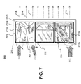
More specifically, as illustrated in FIG. 7 , panel 201 contains noise attenuating inserts 210 a, 201 b and 201 c. Noise attenuating inserts 201 a and 201 b are placed within an airflow path 211 that enters enclosure 210 at inlet point A. The predetermined shapes of attenuating inserts 201 a and 201 b channel the high-speed airflow path 211 having a first direction to a airflow path 211 a having a second direction that is different from the first direction. In this manner, high-speed airflow path 211 may be channeled, for example, to a desired electronic device (not shown) located within the new airflow path 211 a. Similarly, the shapes of noise attenuating insert 201 b channels the airflow path 212 entering at inlet point B. The airflow path 212, in this case, is split into airflow paths 212 a and 212 b due to the shape of noise attenuating insert 201 c. In this manner, the attenuating inserts 201 b and 201 c, by virtue of their predetermined shapes, may channel the cooling air of airflow path 212 to electronic devices (not shown) located in airflow paths 212 a and 212 b. Panel 202 contains noise attenuating inserts 202 a and 202 b. The predetermined shapes of inserts 202 a and 202 b, in this case, are strategically located in the vicinity of a predetermined electronic device (not shown). At least attenuating insert 202 b is located so as to further channel airflow path 212 b. Panel 203 contains noise attenuating inserts 203 a and 203 b having predetermined shapes designed to channel an airflow path 213 entering enclosure 210 at inlet point C. From inlet point C, by virtue of the shapes of noise attenuating inserts 203 a and 203 b, airflow path 213 is channeled into airflow paths 213 a and 213 b, so as to guide the airflow towards desire electronic devices requiring enhanced cooling or to form a desired airflow distribution.
The manner in which noise attenuating system 300 channels the airflow within enclosure 310 is substantially similar to that of the noise attenuating system 200 of FIG. 7 . In FIG. 8 , noise attenuating inserts 301 a and 301 b have predetermined shapes that channel the airflow 312 from inlet point A towards one or more outlet points to form the evenly distributed airflow path 314. Nose attenuating inserts 303 a, 303 b, 303 c and 303 d strategically channel airflow paths 313 to one or more outlet points to form the evenly distributed airflow path 314 or to guide air to predetermined electronic devices (not shown). Noise attenuating inserts 302 a and 302 b may be configured to attenuate noise from an electronic device residing directly behind insert panel 302, and thus not shown. In such a case, noise attenuating insert 302 b represents a noise attenuating insert having a predetermined aerodynamic shape with gently curved surfaces to reduce airflow resistance and increase air moving efficiency. It should be understood, however, that the foregoing non-limiting examples are merely illustrative. Those skilled in the art will be able to devise, based on the foregoing disclosure, other equivalent arrangements in which the various embodiments of the present invention may be implemented and practiced.
In view of the foregoing description of the various embodiments and examples of the noise attenuating system for controlling noise in an electronic equipment cabinet or rack, it is evident that numerous advantages may be obtained through the use predefined shapes (attenuating inserts) made of acoustically absorptive materials arranged in carefully selected positions. The geometry of the inserts is such that, when arranged as disclosed herein, they leave a series of openings that minimize airflow impedance while redistributing (channeling) airflow as is necessary to maximize operational efficiency of the rack's components. The noise attenuating inserts placed within the rack are easily removable, which permit rapid access to electronic devices residing in the racks, thereby improving installation and/or maintenance operations of the electronic devices and attenuating inserts alike.
The corresponding structures, materials, acts, and equivalents of all means or step plus function elements in the claims below are intended to include any structure, material, or act for performing the function in combination with other claimed elements as specifically claimed. The description of the present invention has been presented for purposes of illustration and description, but is not intended to be exhaustive or limited to the invention in the form disclosed. Many modifications and variations will be apparent to those of ordinary skill in the art without departing from the scope and spirit of the invention. The foregoing embodiments and examples were chosen and described in order to best explain the principles of the invention and the practical application, and to enable others of ordinary skill in the art to understand the invention for various embodiments with various modifications as are suited to the particular use contemplated.
Claims (23)
1. A noise attenuating system for controlling noise in an electronic equipment cabinet, the noise attenuating system comprising:
a frame extender configured to be attached to the electronic equipment cabinet; and
one or more noise attenuating inserts configured to be removably attached to the frame extender, the one or more noise attenuating inserts configured to block noise from an electronic device contained in the electronic equipment cabinet.
2. The noise attenuating system of claim 1 , wherein each of the one or more noise attenuating inserts has a predetermined shape.
3. The noise attenuating system of claim 1 , wherein each of the one or more noise attenuating inserts includes an acoustically absorptive material.
4. The noise attenuating system of claim 1 , wherein the one or more noise attenuating inserts are placed in a removable panel.
5. The noise attenuating system of claim 1 , wherein said one or more noise attenuating inserts are further configured to channel airflow at a front section of the frame extender to a back section of the frame extender such that the airflow at the back section of the frame extender is of lower velocity than the airflow at the front of the frame extender.
6. The noise attenuating system of claim 1 , further comprising:
a heat exchanger configured to actively cool air passing therein; and
wherein said frame extender and said one or more noise attenuating inserts are positioned between said electronic equipment cabinet and said heat exchanger.
7. The noise attenuating system of claim 1 , wherein at least two of said noise attenuating inserts are placed within the airflow path to change a direction of flow of air so as to direct the air from an inlet point in said front section of the frame extender towards one or more outlet points in said back section of the frame extender.
8. The noise attenuating system of claim 4 , wherein the removable panel is configured to be pivotably attached to the frame extender.
9. The noise attenuating system of claim 4 , wherein the removable panel is configure to be snapped onto the frame extender.
10. The noise attenuating system of claim 4 , further comprising:
a door attached to the frame extender,
wherein the removable panel is configured to be attached to the door and wherein the one or more noise attenuating inserts protrude into the frame extender.
11. A cabinet for housing one or more electronic devices, the cabinet comprising:
A front door attached to the cabinet;
A back door attached to the cabinet;
A frame extender configured to be attached to the cabinet; and
one or more noise attenuating inserts selectively arranged in the removable panel member, such that the one or more noise attenuating inserts block noise from at least one electronic device contained in the cabinet and channel an airflow path circulating therein; and
wherein said one or more noise attenuating inserts are further configured to channel airflow at a front section of the cabinet to a back section of the cabinet such that airflow at the back section of the cabinet is of lower velocity than the airflow at the front section of the cabinet.
12. The cabinet according to claim 11 , wherein each of the one or more noise attenuating inserts has a predetermined shape.
13. The cabinet according to claim 11 , wherein each of the one or more noise attenuating inserts includes an acoustically absorptive material.
14. The cabinet according to claim 11 wherein the frame extender is configured to be attached to at least one of the front door and the back door and wherein the noise attenuating inserts protrude into the cabinet.
15. A method for controlling noise emanating from electronic equipment housed in a cabinet, the method comprising:
arranging one or more noise attenuating inserts in a removable panel member, the one or more noise attenuating inserts being configured to block noise from at least one electronic device contained in the cabinet;
each of said one or more noise attenuating inserts having a predetermined shape;
at least part of said one or more noise attenuating inserts being configured to channel an airflow path from an inlet point to one or more outlet points; and
attaching a frame extender to the cabinet, wherein the removable panel member is removably attached to the frame extender.
16. The method for controlling noise of claim 15 , wherein each of said one or more noise attenuating inserts include an acoustically absorptive material.
17. The method for controlling noise of claim 15 , further comprising attaching the removable panel member to the cabinet.
18. The method for controlling noise of claim 15 , further comprising snapping the removable panel member onto to the cabinet.
19. The method for controlling noise of claim 15 , wherein
the removable panel member is configured to be removably attached to at least one of a front door and a back door of said cabinet, and
wherein the one or more noise attenuating inserts protrude into the cabinet.
20. The method of controlling noise of claim 15 , further comprising placing said or more noise attenuating inserts within the airflow path to change a direction of the airflow path so as to direct the air from an inlet point towards one or more outlet points of frame extender.
21. The method for controlling noise of claim 15 , wherein said one or more noise attenuating inserts are further configured to channel airflow at a front section of the frame extender to a back section of the frame extender such that the airflow at the back section is of lower velocity than the airflow at the front of the frame extender.
22. The method for controlling noise of claim 21 , further comprising:
attaching a heat exchanger to the frame extender, the heat exchanger configured to actively cool air passing therein,
wherein said frame extender and said one or more noise attenuating inserts are positioned between said cabinet and said heat exchanger.
23. The method for controlling noise of claim 15 , further comprising:
Attaching a door to the frame extender,
Wherein the removable panel member is configured to be attached to the door and wherein the one or more noise attenuating inserts protrude into the frame extender.
Priority Applications (1)
| Application Number | Priority Date | Filing Date | Title |
|---|---|---|---|
| US12/563,513 US8028793B2 (en) | 2009-09-21 | 2009-09-21 | Noise attenuating inserts for electronic equipment cabinets |
Applications Claiming Priority (1)
| Application Number | Priority Date | Filing Date | Title |
|---|---|---|---|
| US12/563,513 US8028793B2 (en) | 2009-09-21 | 2009-09-21 | Noise attenuating inserts for electronic equipment cabinets |
Publications (2)
| Publication Number | Publication Date |
|---|---|
| US20110067948A1 US20110067948A1 (en) | 2011-03-24 |
| US8028793B2 true US8028793B2 (en) | 2011-10-04 |
Family
ID=43755676
Family Applications (1)
| Application Number | Title | Priority Date | Filing Date |
|---|---|---|---|
| US12/563,513 Expired - Fee Related US8028793B2 (en) | 2009-09-21 | 2009-09-21 | Noise attenuating inserts for electronic equipment cabinets |
Country Status (1)
| Country | Link |
|---|---|
| US (1) | US8028793B2 (en) |
Cited By (7)
| Publication number | Priority date | Publication date | Assignee | Title |
|---|---|---|---|---|
| US20140355201A1 (en) * | 2013-05-28 | 2014-12-04 | International Business Machines Corporation | Protecting devices against hot air backflow in a computer system rack having a rear door heat exchanger |
| CN105283028A (en) * | 2014-06-26 | 2016-01-27 | 中兴通讯股份有限公司 | Noise reduction device and method |
| US20160088763A1 (en) * | 2013-06-14 | 2016-03-24 | Abb Technology Ltd | Electrical housing having cooling and sound-absorbing means |
| US9549480B1 (en) | 2015-10-23 | 2017-01-17 | International Business Machines Corporation | Configurable door panels |
| US9936611B1 (en) * | 2014-03-17 | 2018-04-03 | Amazon Technologies, Inc. | Modular mass storage system |
| US10398060B1 (en) * | 2014-03-17 | 2019-08-27 | Amazon Technologies, Inc. | Discrete cooling module |
| US20210383784A1 (en) * | 2018-11-09 | 2021-12-09 | 3M Innovative Properties Company | Blanking panels including acoustic absorbing materials |
Families Citing this family (4)
| Publication number | Priority date | Publication date | Assignee | Title |
|---|---|---|---|---|
| US9025331B2 (en) | 2012-11-12 | 2015-05-05 | International Business Machines Corporation | Inlet-air-cooling door assembly for an electronics rack |
| CN104866041A (en) * | 2015-06-12 | 2015-08-26 | 苏州圣谱拉新材料科技有限公司 | Novel multifunctional chassis |
| CN104914942A (en) * | 2015-06-12 | 2015-09-16 | 苏州圣谱拉新材料科技有限公司 | Novel fish tank cabinet |
| US10244662B2 (en) | 2015-12-11 | 2019-03-26 | International Business Machines Corporation | Method and apparatus for acoustical noise reduction and distributed airflow |
Citations (15)
| Publication number | Priority date | Publication date | Assignee | Title |
|---|---|---|---|---|
| US5544012A (en) | 1993-12-28 | 1996-08-06 | Kabushiki Kaisha Toshiba | Cooling system for cooling electronic apparatus |
| US5926368A (en) | 1996-12-18 | 1999-07-20 | International Business Machines Corporation | Enhanced air cooling system with attached cooling unit |
| US6086476A (en) | 1998-07-31 | 2000-07-11 | Compaq Computer Corporation | Method and apparatus for cooling and acoustic noise reduction in a computer |
| US6104608A (en) | 1997-10-30 | 2000-08-15 | Emc Corporation | Noise reduction hood for an electronic system enclosure |
| US6198627B1 (en) * | 1998-12-17 | 2001-03-06 | Hewlett-Packard Company | Noise reduction back cover for computer devices |
| WO2002071820A1 (en) | 2001-03-05 | 2002-09-12 | Heeseob Park | Soundproofing cabinet with muffler for the noise reduction |
| US6745149B2 (en) | 2000-08-07 | 2004-06-01 | Todd W Beeten | Acoustical noise reducing enclosure for electrical and electronic devices |
| US6816372B2 (en) * | 2003-01-08 | 2004-11-09 | International Business Machines Corporation | System, method and apparatus for noise and heat suppression, and for managing cables in a computer system |
| US20060232945A1 (en) * | 2005-04-18 | 2006-10-19 | International Business Machines Corporation | Apparatus and method for facilitating cooling of an electronics rack employing a heat exchange assembly mounted to an outlet door cover of the electronics rack |
| US20070139882A1 (en) * | 2005-12-15 | 2007-06-21 | International Business Machines Corporation | Method and apparatus for acoustic noise reduction in a computer system having a vented cover |
| US7286348B2 (en) | 2004-11-16 | 2007-10-23 | Hewlett-Packard Development Company, L.P. | Housing assembly for a computer |
| US20070274036A1 (en) * | 2006-03-17 | 2007-11-29 | Kell Systems | Noise Proofed Ventilated Air Intake Chamber for Electronics Equipment Enclosure |
| US7379299B2 (en) * | 2006-03-17 | 2008-05-27 | Kell Systems | Noiseproofed and ventilated enclosure for electronics equipment |
| US7549505B1 (en) * | 2005-02-04 | 2009-06-23 | Kawar Maher S | Acoustic noise reduction device for electronic equipment, including personal computers |
| US7800895B2 (en) * | 2006-10-02 | 2010-09-21 | Sony Corporation | Electronic apparatus and sound insulating method thereof |
-
2009
- 2009-09-21 US US12/563,513 patent/US8028793B2/en not_active Expired - Fee Related
Patent Citations (17)
| Publication number | Priority date | Publication date | Assignee | Title |
|---|---|---|---|---|
| US5544012A (en) | 1993-12-28 | 1996-08-06 | Kabushiki Kaisha Toshiba | Cooling system for cooling electronic apparatus |
| US5926368A (en) | 1996-12-18 | 1999-07-20 | International Business Machines Corporation | Enhanced air cooling system with attached cooling unit |
| US6104608A (en) | 1997-10-30 | 2000-08-15 | Emc Corporation | Noise reduction hood for an electronic system enclosure |
| US6086476A (en) | 1998-07-31 | 2000-07-11 | Compaq Computer Corporation | Method and apparatus for cooling and acoustic noise reduction in a computer |
| US6198627B1 (en) * | 1998-12-17 | 2001-03-06 | Hewlett-Packard Company | Noise reduction back cover for computer devices |
| US6745149B2 (en) | 2000-08-07 | 2004-06-01 | Todd W Beeten | Acoustical noise reducing enclosure for electrical and electronic devices |
| WO2002071820A1 (en) | 2001-03-05 | 2002-09-12 | Heeseob Park | Soundproofing cabinet with muffler for the noise reduction |
| US6816372B2 (en) * | 2003-01-08 | 2004-11-09 | International Business Machines Corporation | System, method and apparatus for noise and heat suppression, and for managing cables in a computer system |
| US7286348B2 (en) | 2004-11-16 | 2007-10-23 | Hewlett-Packard Development Company, L.P. | Housing assembly for a computer |
| US7549505B1 (en) * | 2005-02-04 | 2009-06-23 | Kawar Maher S | Acoustic noise reduction device for electronic equipment, including personal computers |
| US20060232945A1 (en) * | 2005-04-18 | 2006-10-19 | International Business Machines Corporation | Apparatus and method for facilitating cooling of an electronics rack employing a heat exchange assembly mounted to an outlet door cover of the electronics rack |
| US7385810B2 (en) * | 2005-04-18 | 2008-06-10 | International Business Machines Corporation | Apparatus and method for facilitating cooling of an electronics rack employing a heat exchange assembly mounted to an outlet door cover of the electronics rack |
| US20070139882A1 (en) * | 2005-12-15 | 2007-06-21 | International Business Machines Corporation | Method and apparatus for acoustic noise reduction in a computer system having a vented cover |
| US20070274036A1 (en) * | 2006-03-17 | 2007-11-29 | Kell Systems | Noise Proofed Ventilated Air Intake Chamber for Electronics Equipment Enclosure |
| US7379299B2 (en) * | 2006-03-17 | 2008-05-27 | Kell Systems | Noiseproofed and ventilated enclosure for electronics equipment |
| US7782612B2 (en) * | 2006-03-17 | 2010-08-24 | Kell Systems | Noiseproofed and ventilated air intake chamber for electronics equipment enclosure |
| US7800895B2 (en) * | 2006-10-02 | 2010-09-21 | Sony Corporation | Electronic apparatus and sound insulating method thereof |
Cited By (14)
| Publication number | Priority date | Publication date | Assignee | Title |
|---|---|---|---|---|
| US9137930B2 (en) * | 2013-05-28 | 2015-09-15 | Lenovo Enterprise Solutions (Singapore) Pte. Ltd. | Protecting devices against hot air backflow in a computer system rack having a rear door heat exchanger |
| US20140355201A1 (en) * | 2013-05-28 | 2014-12-04 | International Business Machines Corporation | Protecting devices against hot air backflow in a computer system rack having a rear door heat exchanger |
| US9504182B2 (en) * | 2013-06-14 | 2016-11-22 | Abb Technology Ltd | Electrical housing having cooling and sound-absorbing means |
| US20160088763A1 (en) * | 2013-06-14 | 2016-03-24 | Abb Technology Ltd | Electrical housing having cooling and sound-absorbing means |
| US9936611B1 (en) * | 2014-03-17 | 2018-04-03 | Amazon Technologies, Inc. | Modular mass storage system |
| US10398060B1 (en) * | 2014-03-17 | 2019-08-27 | Amazon Technologies, Inc. | Discrete cooling module |
| US10426060B2 (en) | 2014-03-17 | 2019-09-24 | Amazon Technologies, Inc. | Modular mass storage system |
| US11553626B2 (en) | 2014-03-17 | 2023-01-10 | Amazon Technologies, Inc. | Discrete cooling module |
| CN105283028A (en) * | 2014-06-26 | 2016-01-27 | 中兴通讯股份有限公司 | Noise reduction device and method |
| CN105283028B (en) * | 2014-06-26 | 2019-07-09 | 中兴通讯股份有限公司 | A kind of denoising device and method |
| US9549480B1 (en) | 2015-10-23 | 2017-01-17 | International Business Machines Corporation | Configurable door panels |
| US10362716B2 (en) | 2015-10-23 | 2019-07-23 | Intemational Business Machines Corporation | Configurable door panels |
| US11202397B2 (en) | 2015-10-23 | 2021-12-14 | International Business Machines Corporation | Configurable door panels |
| US20210383784A1 (en) * | 2018-11-09 | 2021-12-09 | 3M Innovative Properties Company | Blanking panels including acoustic absorbing materials |
Also Published As
| Publication number | Publication date |
|---|---|
| US20110067948A1 (en) | 2011-03-24 |
Similar Documents
| Publication | Publication Date | Title |
|---|---|---|
| US8028793B2 (en) | Noise attenuating inserts for electronic equipment cabinets | |
| US11880247B2 (en) | Air directing device | |
| US9936612B2 (en) | Apparatus, system, and method for configuring a system of electronic chassis | |
| US8934242B2 (en) | Hot aisle containment cooling system and method | |
| US7286345B2 (en) | Rack-mounted air deflector | |
| US7372695B2 (en) | Directional fan assembly | |
| US7508663B2 (en) | Computer rack cooling system with variable airflow impedance | |
| US6859366B2 (en) | Data center cooling system | |
| EP2298051B1 (en) | Rack mounted cooling unit | |
| US20120049706A1 (en) | Air Flow Management Enclosure | |
| US20100315788A1 (en) | Side-exhaust cooling system for rack mounted equipment | |
| US10939588B2 (en) | Airflow distribution and management architecture for large data center | |
| US10334748B1 (en) | Top-mount cable management structure(s) for an electronics rack | |
| US20170234573A1 (en) | Baffle for directing air flow in a rack | |
| US20230380112A1 (en) | Airflow management system for power module | |
| JP2006032842A (en) | Rack cooling device, rack and computer system |
Legal Events
| Date | Code | Title | Description |
|---|---|---|---|
| AS | Assignment |
Owner name: INTERNATIONAL BUSINESS MACHINES CORPORATION, NEW Y Free format text: ASSIGNMENT OF ASSIGNORS INTEREST;ASSIGNOR:BARD, SETH E.;REEL/FRAME:023259/0130 Effective date: 20090921 |
|
| REMI | Maintenance fee reminder mailed | ||
| LAPS | Lapse for failure to pay maintenance fees | ||
| STCH | Information on status: patent discontinuation |
Free format text: PATENT EXPIRED DUE TO NONPAYMENT OF MAINTENANCE FEES UNDER 37 CFR 1.362 |
|
| FP | Lapsed due to failure to pay maintenance fee |
Effective date: 20151004 |