US8028377B2 - Shoe support terminal connection for block and tackle balance - Google Patents
Shoe support terminal connection for block and tackle balance Download PDFInfo
- Publication number
- US8028377B2 US8028377B2 US12/022,565 US2256508A US8028377B2 US 8028377 B2 US8028377 B2 US 8028377B2 US 2256508 A US2256508 A US 2256508A US 8028377 B2 US8028377 B2 US 8028377B2
- Authority
- US
- United States
- Prior art keywords
- terminal connector
- balance
- shoe
- assembly
- cord
- Prior art date
- Legal status (The legal status is an assumption and is not a legal conclusion. Google has not performed a legal analysis and makes no representation as to the accuracy of the status listed.)
- Active, expires
Links
- 238000000034 method Methods 0.000 claims description 12
- 230000003247 decreasing effect Effects 0.000 claims description 3
- 238000000465 moulding Methods 0.000 claims description 2
- 239000002184 metal Substances 0.000 description 3
- 230000000881 depressing effect Effects 0.000 description 1
- 238000003780 insertion Methods 0.000 description 1
- 230000037431 insertion Effects 0.000 description 1
Images


Classifications
-
- E—FIXED CONSTRUCTIONS
- E05—LOCKS; KEYS; WINDOW OR DOOR FITTINGS; SAFES
- E05D—HINGES OR SUSPENSION DEVICES FOR DOORS, WINDOWS OR WINGS
- E05D13/00—Accessories for sliding or lifting wings, e.g. pulleys, safety catches
- E05D13/10—Counterbalance devices
- E05D13/12—Counterbalance devices with springs
- E05D13/1207—Counterbalance devices with springs with tension springs
-
- E—FIXED CONSTRUCTIONS
- E05—LOCKS; KEYS; WINDOW OR DOOR FITTINGS; SAFES
- E05D—HINGES OR SUSPENSION DEVICES FOR DOORS, WINDOWS OR WINGS
- E05D15/00—Suspension arrangements for wings
- E05D15/16—Suspension arrangements for wings for wings sliding vertically more or less in their own plane
- E05D15/22—Suspension arrangements for wings for wings sliding vertically more or less in their own plane allowing an additional movement
-
- E—FIXED CONSTRUCTIONS
- E05—LOCKS; KEYS; WINDOW OR DOOR FITTINGS; SAFES
- E05Y—INDEXING SCHEME RELATING TO HINGES OR OTHER SUSPENSION DEVICES FOR DOORS, WINDOWS OR WINGS AND DEVICES FOR MOVING WINGS INTO OPEN OR CLOSED POSITION, CHECKS FOR WINGS AND WING FITTINGS NOT OTHERWISE PROVIDED FOR, CONCERNED WITH THE FUNCTIONING OF THE WING
- E05Y2201/00—Constructional elements; Accessories therefore
- E05Y2201/60—Suspension or transmission members; Accessories therefore
- E05Y2201/622—Suspension or transmission members elements
- E05Y2201/644—Flexible elongated pulling elements; Members cooperating with flexible elongated pulling elements
- E05Y2201/654—Cables
-
- E—FIXED CONSTRUCTIONS
- E05—LOCKS; KEYS; WINDOW OR DOOR FITTINGS; SAFES
- E05Y—INDEXING SCHEME RELATING TO HINGES OR OTHER SUSPENSION DEVICES FOR DOORS, WINDOWS OR WINGS AND DEVICES FOR MOVING WINGS INTO OPEN OR CLOSED POSITION, CHECKS FOR WINGS AND WING FITTINGS NOT OTHERWISE PROVIDED FOR, CONCERNED WITH THE FUNCTIONING OF THE WING
- E05Y2201/00—Constructional elements; Accessories therefore
- E05Y2201/60—Suspension or transmission members; Accessories therefore
- E05Y2201/622—Suspension or transmission members elements
- E05Y2201/644—Flexible elongated pulling elements; Members cooperating with flexible elongated pulling elements
- E05Y2201/658—Members cooperating with flexible elongated pulling elements
- E05Y2201/668—Pulleys; Wheels
- E05Y2201/67—Pulleys; Wheels in tackles
-
- E—FIXED CONSTRUCTIONS
- E05—LOCKS; KEYS; WINDOW OR DOOR FITTINGS; SAFES
- E05Y—INDEXING SCHEME RELATING TO HINGES OR OTHER SUSPENSION DEVICES FOR DOORS, WINDOWS OR WINGS AND DEVICES FOR MOVING WINGS INTO OPEN OR CLOSED POSITION, CHECKS FOR WINGS AND WING FITTINGS NOT OTHERWISE PROVIDED FOR, CONCERNED WITH THE FUNCTIONING OF THE WING
- E05Y2900/00—Application of doors, windows, wings or fittings thereof
- E05Y2900/10—Application of doors, windows, wings or fittings thereof for buildings or parts thereof
- E05Y2900/13—Application of doors, windows, wings or fittings thereof for buildings or parts thereof characterised by the type of wing
- E05Y2900/148—Windows
-
- Y—GENERAL TAGGING OF NEW TECHNOLOGICAL DEVELOPMENTS; GENERAL TAGGING OF CROSS-SECTIONAL TECHNOLOGIES SPANNING OVER SEVERAL SECTIONS OF THE IPC; TECHNICAL SUBJECTS COVERED BY FORMER USPC CROSS-REFERENCE ART COLLECTIONS [XRACs] AND DIGESTS
- Y10—TECHNICAL SUBJECTS COVERED BY FORMER USPC
- Y10T—TECHNICAL SUBJECTS COVERED BY FORMER US CLASSIFICATION
- Y10T29/00—Metal working
- Y10T29/49—Method of mechanical manufacture
- Y10T29/49826—Assembling or joining
- Y10T29/49908—Joining by deforming
Definitions
- the invention pertains to the field of windows. More particularly, the invention pertains to a window balance.
- Block and tackle window balances are compact in size and relatively easy to install. They use a system of pulleys and an extension spring to convert high spring tension applied over a short working distance to a lower spring tension applied over a longer working distance. Both the spring and the pulley system are arranged within a rigid U-shaped balance channel. One end of the extension spring is anchored at a first end of the balance channel, while the other end of the extension spring is mounted to an intermediate pulley or middle carriage of the pulley system. The second pulley of the pulley system is anchored at the second end of the balance channel. Generally, the balance channel is mounted in the jamb of the window frame and the cord for the pulley system is attached to a sash shoe that slides in the jamb with the sash.
- a prior art block and tackle balance 110 is constructed from a channel 112 , commonly formed from sheet metal, into which a spring 114 is assembled.
- the first spring end 114 A of the spring 114 may be affixed by various means proximate a first end 112 A of the channel 112 .
- the second spring end 114 B of the spring 114 is attached to a middle carriage 116 , the middle carriage 116 including the first portion of a multi-part balance tackle assembly.
- An end axle 118 including a second portion of the multipart balance tackle assembly is affixed proximate a second end 112 B of the channel 112 .
- a sash cord 120 is affixed at one end to the middle carriage 116 and twice passes alternatively around sheaves including the end axle 118 and the middle carriage 116 , exiting finally at the second end 112 B of the channel 112 , to form a five-part balance tackle assembly.
- a cord terminal 122 is affixed to the second end of the sash cord 120 , to facilitate attachment of the sash cord 120 in the application of the counterbalance and to prevent the second end of the sash cord 120 from being retracted into the second end of the channel 112 .
- the cord terminal 122 is then mounted in a carrier or balance shoe, which slides up and down a frame channel when the window is opened and closed.
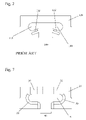
- a cord terminal is mounted in a balance shoe 128 , the top surface of which is shown in FIG. 2 .
- the balance shoe 128 has a gap 146 for insertion of the cord terminal (not shown) and a pocket 148 for mounting the cord terminal in the balance shoe 128 .
- the balance shoe 128 has flexible tabs 132 , which help to maintain the mounted cord terminal in the pocket 148 of the balance shoe 128 .
- the tabs 132 are flexible primarily in a direction perpendicular to the long axis of the pocket 148 . These tabs 132 do not sufficiently limit motion of a mounted cord terminal in the pocket and have been found to break during usage in a block and tackle balance assembly. These tabs 132 also bear some of the load from the upward force of the block and tackle assembly as applied to the shoe by the cord terminal during operation.
- the balance shoe holds and upwardly biases the terminal connector in a mounted position.
- a biasing element of the shoe maintains the terminal connector in a pocket of the shoe during operation of the balance.
- the terminal connector is prevented from laterally exiting the pocket in the mounted position by a widened portion on the terminal connector and a locating surface extending from the shoe toward the pocket. Manually pressing down on the biasing element or the terminal connector itself to lower the terminal connector in the pocket until the widened portion clears the locating surface allows lateral removal of the terminal connector from the pocket.
- the terminal connector does not experience a sufficient downward force to overcome the upward bias such that the widened portion never clears the locating surface.
- the block and tackle window balance assembly includes a terminal connector attached to a sash cord and a balance shoe.
- the balance shoe includes a biasing element for biasing the terminal connector in an upward direction toward the sash cord in a mounted position in the balance shoe.
- the terminal connector is only removable from the balance shoe by applying a downward force against the biasing element.
- the block and tackle window balance assembly includes a terminal connector attached to a sash cord and a balance shoe.
- the balance shoe includes a biasing element for biasing the terminal connector in an upward direction toward the sash cord in a mounted position in the balance shoe.
- the balance shoe also includes a retaining surface for limiting upward movement of the terminal connector when mounted in the balance shoe.
- the balance shoe further includes a locating surface limiting lateral movement of the terminal connector in the balance shoe unless an upward bias of the biasing element is overcome such that the terminal connector is lowered from the mounted position and a widened portion of the terminal connector laterally clears the locating surface.
- a method of assembling a block and tackle window balance includes inserting a terminal connector for attachment to a sash cord through a gap in a balance shoe.
- the method also includes moving the terminal connector laterally toward a pocket of the balance shoe with a widened portion of the terminal connector remaining below an extension on the balance shoe while a ridge of the connector increasingly applies a downward force to a biasing element of the balance shoe until the widened portion clears the extension.
- the method further includes raising the terminal connector upward in the pocket to a mounted position, thereby decreasing loading of the biasing element, wherein a retaining surface of the balance shoe limits upward movement of the terminal connector and a locating surface on the extension limits lateral movement of the widened portion when the terminal connector is in the mounted position.
- a method of maintaining a terminal connector for a sash cord in a mounted position in a balance shoe of a block and tackle window balance assembly includes applying an upward bias toward the sash cord to the terminal connector in the mounted position.
- the method also includes limiting lateral movement of the terminal connector in the mounted position by a locating surface extending from the balance shoe toward a widened portion of the terminal connector unless the upward bias is overcome such that the terminal connector is lowered from the mounted position and the widened portion laterally clears the locating surface.
- FIG. 1 shows a perspective view of a prior art block and tackle balance.
- FIG. 2 shows a top view of the top surfaces of a prior art balance shoe.
- FIG. 3 shows a back view of a block and tackle balance in an embodiment of the present invention.
- FIG. 4 shows an expanded view of the circle region 4 of FIG. 3 .
- FIG. 5 shows a front view of the block and tackle balance of FIG. 3 .
- FIG. 6 shows an expanded view of the circle region 6 of FIG. 5 .
- FIG. 7 shows a top view of the top surfaces of the shoe in the embodiment of FIGS. 3-6 .
- FIG. 8 shows a back view of a shoe and terminal connector in an embodiment of the present invention.
- FIG. 9 shows a cross sectional view taken along the plane 9 - 9 of FIG. 8 .
- FIG. 10 shows a cross sectional view taken along the plane 10 - 10 of FIG. 8 .
- FIG. 11 shows a preferred block and tackle balance for use in the present invention.
- the shoe holds and upwardly biases the terminal connector in a shoe and terminal connector assembly for a block and tackle window balance.
- the terminal connector is preferably made of metal or plastic, and the shoe is preferably made of plastic.
- the upward biasing of the terminal connector by a biasing element of the shoe maintains the terminal connector in a pocket of the shoe during operation of the block and tackle balance.
- the terminal connector is prevented from laterally coming out of the pocket when in the mounted position by a widened portion on the terminal connector and a locating surface extending from the shoe toward the pocket.
- the terminal connector is easily removed by manually pressing down on the biasing element or the terminal connector itself to lower the terminal connector in the pocket until the widened portion on the terminal connector clears the locating surface, thereby allowing lateral removal of the terminal connector from the pocket.
- the terminal connector is easily removed manually from the shoe, during normal operation of the block and tackle balance the terminal connector does not experience a sufficient downward force to overcome the upward bias such that the widened portion of the terminal connector never clears the locating surface.
- a sash cord 20 exits at the second end 22 B of a channel 22 where it is attached to a terminal connector 24 with an axial bore, through which the cord 20 is threaded.
- the cord 20 is then knotted 26 to maintain the terminal connector 24 on the cord 20 .
- the terminal connector is molded around the cord, as shown in FIG. 1 .
- the terminal connector 24 is mounted to a balance shoe 28 , which is mountable and slidable up and down in a frame channel.
- a retaining surface 30 in the shoe 28 and a widened portion 31 on the terminal connector 24 limit upward movement of the terminal connector 24 in the pocket 48 of the shoe 28 .
- the shoe 28 also includes a biasing element, which in this embodiment is a flexible tab 32 .
- the flexible tab 32 is located on a top surface of the shoe 28 and applies an upward biasing force on the terminal connector 24 by contacting a ridge 34 on the terminal connector 24 , and resisting downward movement of the terminal connector 24 in the pocket 48 .
- the tab 32 is preferably deflected slightly downward by the ridge 34 such that the terminal connector 24 is biased to be maintained in the balance shoe 28 in the position shown in FIG. 10 .
- the flexible tabs 32 flex substantially in a vertical direction with respect to the shoe 28 to bias the terminal connector 24 in an upward direction, in contrast to the prior art shoe 128 of FIG. 2 , in which the flexible tabs 132 flex substantially in a horizontal direction with respect to the shoe 128 to bias the cord terminal in an inward direction toward the pocket.
- the terminal connector 24 and shoe 28 are preferably part of a block and tackle balance assembly 36 further including the block and tackle channel 22 , commonly formed from sheet metal, into which a spring 38 and the pulley system of the sash cord 20 are assembled.
- the first spring end 38 A of the spring 38 may be affixed by various means proximate a first end 22 A of the channel 22 .
- the second spring end 38 B is attached to a middle carriage 40 , which includes a middle axle 42 .
- the sash cord 20 is laced around the middle axle 42 and an end axle 44 , which is affixed proximate a second end 22 B of the channel 22 .
- the sash cord 20 is affixed at one end to the middle carriage 40 and twice passes alternatively around sheaves including the end axle 44 and the middle axle 42 , exiting finally at the second end 22 B of the channel 22 .
- the terminal connector 24 is preferably inserted through a gap 46 in the shoe 28 with the widened portion 31 below an extension 52 on the shoe 28 .
- the terminal connector 24 is then slid laterally toward the pocket 48 with the ridge 34 increasingly depressing the tab 32 until the widened portion 31 clears the extension 52 .
- the terminal connector 24 is then raised in the pocket 48 , aided by the bias of the tab and thereby decreasing depression of the tab 32 , until an upper surface of the widened portion 31 contacts the retaining surface 30 .
- the extension 52 preferably has a locating surface 54 lateral to the widened portion 31 to hold the terminal connector 54 in the pocket 48 .
- the top surface of the shoe 28 preferably has a tab support 50 lining at least part of the top edge of the pocket 48 .
- the tab support 50 resists excessive downward flexing and potential fracturing of the tab 32 by resisting excessive downward motion of the mounted terminal connector 24 .
- the tab support 50 combines with the tab 32 to resist downward motion of the terminal connector 24 after the terminal connector has deflected the tab 32 downward enough that the terminal connector 24 contacts the tab support 50 .
- the tab support 50 ramps upward from a top edge of the pocket 48 near the gap 46 toward the edge where the tab 32 is located.
- the tab support 50 may have other shapes, including but not limited to a horizontal, stepped, or curved profile, within the spirit of the present invention to support the tab 32 in the case of any excessive downward force from the terminal connector 24 .
- the tab support 50 is preferably rigidly fixed as a hard stop to prevent the tab 32 from flexing downward to the point that it breaks.
- shoe 28 in the embodiments of FIG. 3 through FIG. 10 has left-right symmetry and a pocket 48 and flexible tab 32 on each side for mounting of a terminal connector 24 on each side, a shoe may have only one pocket and one flexible tab for mounting a single terminal connector within the spirit of the present invention.
- FIG. 11 shows a preferred block and tackle balance 10 for use in the present invention.
- the balance 10 is constructed from a channel 12 into which a spring 14 is assembled.
- the first spring end 14 A of the spring 14 may be affixed by various means proximate a first end 12 A of the channel 12 .
- the second spring end 14 B of the spring 14 is attached to a middle carriage 16 , the middle carriage 16 including the first portion of a multi-part balance tackle assembly.
- An end axle 18 including a second portion of the multipart balance tackle assembly is affixed proximate a second end 12 B of the channel 12 .
- the sash cord 20 is affixed at one end to the middle carriage 16 and passes alternatively around sheaves including the end axle 18 and the middle carriage 16 .
- the sash cord 20 exits at the second end 12 B of the channel 12 , where it is attached to a terminal connector 24 with an axial bore, through which the cord 20 is threaded.
- the cord 20 is then secured 26 to maintain the terminal connector 24 on the cord 20 .
- the cord is shown as knotted in FIG. 11 to maintain the terminal connector on the cord, any method to secure or attach the terminal connector to the cord, including, but not limited to, knotting, molding, adhering, clamping, and clasping, may be used within the spirit of the present invention.
- the widened portion 31 and the ridge 34 of the terminal connector 24 are also shown in FIG. 11 .
Abstract
Description
Claims (20)
Priority Applications (1)
| Application Number | Priority Date | Filing Date | Title |
|---|---|---|---|
| US12/022,565 US8028377B2 (en) | 2008-01-30 | 2008-01-30 | Shoe support terminal connection for block and tackle balance |
Applications Claiming Priority (1)
| Application Number | Priority Date | Filing Date | Title |
|---|---|---|---|
| US12/022,565 US8028377B2 (en) | 2008-01-30 | 2008-01-30 | Shoe support terminal connection for block and tackle balance |
Publications (2)
| Publication Number | Publication Date |
|---|---|
| US20090188075A1 US20090188075A1 (en) | 2009-07-30 |
| US8028377B2 true US8028377B2 (en) | 2011-10-04 |
Family
ID=40897749
Family Applications (1)
| Application Number | Title | Priority Date | Filing Date |
|---|---|---|---|
| US12/022,565 Active 2029-09-25 US8028377B2 (en) | 2008-01-30 | 2008-01-30 | Shoe support terminal connection for block and tackle balance |
Country Status (1)
| Country | Link |
|---|---|
| US (1) | US8028377B2 (en) |
Cited By (1)
| Publication number | Priority date | Publication date | Assignee | Title |
|---|---|---|---|---|
| US10787849B1 (en) * | 2019-07-01 | 2020-09-29 | Ply Gem Industries, Inc. | Sash balance for vertical slider window |
Families Citing this family (9)
| Publication number | Priority date | Publication date | Assignee | Title |
|---|---|---|---|---|
| US6679000B2 (en) | 2001-01-12 | 2004-01-20 | Amesbury Group, Inc. | Snap lock balance shoe and system for a pivotable window |
| CA2736316C (en) * | 2010-04-06 | 2018-02-27 | Amesbury Group, Inc. | Inverted constant force window balance for tilt sash |
| US9109386B2 (en) | 2012-12-03 | 2015-08-18 | Marvin Lumber And Cedar Company | Window sash counterbalance with independently operable sashes |
| US10563441B2 (en) | 2015-11-20 | 2020-02-18 | Amesbury Group, Inc. | Constant force window balance engagement system |
| US10563440B2 (en) | 2017-04-07 | 2020-02-18 | Amesbury Group, Inc. | Inverted constant force window balance |
| US11193318B2 (en) | 2017-09-21 | 2021-12-07 | Amesbury Group, Inc. | Window balance shoes for a pivotable window |
| CH715230B1 (en) * | 2018-08-06 | 2022-06-30 | Hawa Sliding Solutions Ag | Sliding door arrangement with a device for closing the sliding door. |
| US11352821B2 (en) | 2019-01-09 | 2022-06-07 | Amesbury Group, Inc. | Inverted constant force window balance having slidable coil housing |
| US11560743B2 (en) * | 2019-04-02 | 2023-01-24 | Amesbury Group, Inc. | Window balance systems |
Citations (9)
| Publication number | Priority date | Publication date | Assignee | Title |
|---|---|---|---|---|
| US4654928A (en) | 1986-04-11 | 1987-04-07 | Caldwell Manufacturing Company | Adjustable friction block and tackle window balance system |
| US4689850A (en) | 1986-06-30 | 1987-09-01 | Caldwell Manufacturing Company | Pulley mount for window balance system |
| US5530991A (en) | 1994-01-21 | 1996-07-02 | Caldwell Manufacturing Company | Block and tackle window balance |
| US6041476A (en) | 1997-11-21 | 2000-03-28 | Caldwell Manufacturing Company | Inverted block and tackle window balance |
| US6622342B1 (en) * | 2001-06-06 | 2003-09-23 | Ashland Products, Inc. | Block and tackle balance assembly with brake shoe |
| US6820368B2 (en) * | 2001-01-12 | 2004-11-23 | Amesbury Group, Inc. | Snap lock balance shoe and system for a pivotable window |
| US20060000058A1 (en) | 2004-06-21 | 2006-01-05 | Caldwell Manufacturing Company | Block and tackle window balance with integrally molded middle carriage assembly and cord |
| US7069621B2 (en) * | 2003-02-21 | 2006-07-04 | Pomeroy, Incorporated | Block and tackle sash balance shoe |
| US7735192B2 (en) * | 2006-06-28 | 2010-06-15 | Caldwell Manufacturing Company | Extended travel window balance |
-
2008
- 2008-01-30 US US12/022,565 patent/US8028377B2/en active Active
Patent Citations (9)
| Publication number | Priority date | Publication date | Assignee | Title |
|---|---|---|---|---|
| US4654928A (en) | 1986-04-11 | 1987-04-07 | Caldwell Manufacturing Company | Adjustable friction block and tackle window balance system |
| US4689850A (en) | 1986-06-30 | 1987-09-01 | Caldwell Manufacturing Company | Pulley mount for window balance system |
| US5530991A (en) | 1994-01-21 | 1996-07-02 | Caldwell Manufacturing Company | Block and tackle window balance |
| US6041476A (en) | 1997-11-21 | 2000-03-28 | Caldwell Manufacturing Company | Inverted block and tackle window balance |
| US6820368B2 (en) * | 2001-01-12 | 2004-11-23 | Amesbury Group, Inc. | Snap lock balance shoe and system for a pivotable window |
| US6622342B1 (en) * | 2001-06-06 | 2003-09-23 | Ashland Products, Inc. | Block and tackle balance assembly with brake shoe |
| US7069621B2 (en) * | 2003-02-21 | 2006-07-04 | Pomeroy, Incorporated | Block and tackle sash balance shoe |
| US20060000058A1 (en) | 2004-06-21 | 2006-01-05 | Caldwell Manufacturing Company | Block and tackle window balance with integrally molded middle carriage assembly and cord |
| US7735192B2 (en) * | 2006-06-28 | 2010-06-15 | Caldwell Manufacturing Company | Extended travel window balance |
Cited By (1)
| Publication number | Priority date | Publication date | Assignee | Title |
|---|---|---|---|---|
| US10787849B1 (en) * | 2019-07-01 | 2020-09-29 | Ply Gem Industries, Inc. | Sash balance for vertical slider window |
Also Published As
| Publication number | Publication date |
|---|---|
| US20090188075A1 (en) | 2009-07-30 |
Similar Documents
| Publication | Publication Date | Title |
|---|---|---|
| US8028377B2 (en) | Shoe support terminal connection for block and tackle balance | |
| US20060037249A1 (en) | Ascending/descending door glass support structure | |
| JP4521039B2 (en) | Sunroof device slider structure | |
| AU2004222814B8 (en) | Mounting device for a guide cord | |
| US8490331B2 (en) | Roller for a sliding panel assembly, and method of installing a sliding panel assembly | |
| US20070180773A1 (en) | Dual-guided single rail window regulator | |
| US20030213096A1 (en) | Block and tackle balance assembly with brake shoe | |
| KR20130087458A (en) | Sheet guide of sheet shutter | |
| US4949425A (en) | Spring loaded block and tackle window sash balance assembly | |
| TW200307083A (en) | Shutter device with flexible lateral edges | |
| US6305125B1 (en) | Window guide having a plurality of contact members attached at only one end for guiding an automobile door window | |
| US20100088964A1 (en) | Snap-in glass retention for a vehicle door | |
| US20080000047A1 (en) | Extended Travel Window Balance | |
| US20110041287A1 (en) | Side load carrier and balance system for window sashes | |
| US20090193718A1 (en) | Snap-in Lifter Plate | |
| KR20130003972A (en) | Protecting device for pushing of elevator | |
| CN102040149A (en) | Door device of elevator hall | |
| KR102229589B1 (en) | Fixing apparatus for easy detachable on din rail | |
| KR20220072447A (en) | Windows regulator for vehicle | |
| KR200303509Y1 (en) | stoper of fixing rail for terminal block | |
| CN217080088U (en) | Pulley door presss from both sides structure suitable for bathroom door | |
| JP2002129831A (en) | Mobile body position regulating structure for window regulator | |
| CN110984765A (en) | Motor underlying window lifter system for automobile window | |
| CN217129247U (en) | Bathroom door | |
| JP3571130B2 (en) | Wind glass lift guide device |
Legal Events
| Date | Code | Title | Description |
|---|---|---|---|
| AS | Assignment |
Owner name: CALDWELL MANUFACTURING COMPANY, NEW YORK Free format text: ASSIGNMENT OF ASSIGNORS INTEREST;ASSIGNOR:BAKER, MARK R.;REEL/FRAME:020441/0293 Effective date: 20080130 |
|
| AS | Assignment |
Owner name: CALDWELL MANUFACTURING COMPANY OF NORTH AMERICA LL Free format text: ASSIGNMENT OF ASSIGNORS INTEREST;ASSIGNOR:CALDWELL MANUFACTURING COMPANY, THE;REEL/FRAME:026110/0223 Effective date: 20110329 |
|
| STCF | Information on status: patent grant |
Free format text: PATENTED CASE |
|
| FPAY | Fee payment |
Year of fee payment: 4 |
|
| AS | Assignment |
Owner name: CALDWELL MANUFACTURING COMPANY NORTH AMERICA, LLC, Free format text: CORRECTIVE ASSIGNMENT TO CORRECT THE ASSIGNOR NAME PREVIOUSLY RECORDED AT REEL: 026110 FRAME: 0223. ASSIGNOR(S) HEREBY CONFIRMS THE ASSIGNMENT;ASSIGNOR:THE CALDWELL MANUFACTURING COMPANY;REEL/FRAME:037681/0094 Effective date: 20110329 |
|
| MAFP | Maintenance fee payment |
Free format text: PAYMENT OF MAINTENANCE FEE, 8TH YEAR, LARGE ENTITY (ORIGINAL EVENT CODE: M1552); ENTITY STATUS OF PATENT OWNER: LARGE ENTITY Year of fee payment: 8 |
|
| MAFP | Maintenance fee payment |
Free format text: PAYMENT OF MAINTENANCE FEE, 12TH YEAR, LARGE ENTITY (ORIGINAL EVENT CODE: M1553); ENTITY STATUS OF PATENT OWNER: LARGE ENTITY Year of fee payment: 12 |
|
| AS | Assignment |
Owner name: ASSA ABLOY FENESTRATION, LLC, NEW YORK Free format text: CHANGE OF NAME;ASSIGNOR:CALDWELL MANUFACTURING COMPANY NORTH AMERICA, LLC;REEL/FRAME:066033/0394 Effective date: 20231130 |