US8027159B2 - Fixing mechanism for fixing a removable module of an electronic device - Google Patents
Fixing mechanism for fixing a removable module of an electronic device Download PDFInfo
- Publication number
- US8027159B2 US8027159B2 US12/464,112 US46411209A US8027159B2 US 8027159 B2 US8027159 B2 US 8027159B2 US 46411209 A US46411209 A US 46411209A US 8027159 B2 US8027159 B2 US 8027159B2
- Authority
- US
- United States
- Prior art keywords
- component
- wedging
- fixing
- housing
- bolt
- Prior art date
- Legal status (The legal status is an assumption and is not a legal conclusion. Google has not performed a legal analysis and makes no representation as to the accuracy of the status listed.)
- Expired - Fee Related, expires
Links
- 230000003287 optical effect Effects 0.000 claims description 2
- 238000010586 diagram Methods 0.000 description 2
- 230000004075 alteration Effects 0.000 description 1
- 238000000034 method Methods 0.000 description 1
- 238000012986 modification Methods 0.000 description 1
- 230000004048 modification Effects 0.000 description 1
Images


Classifications
-
- G—PHYSICS
- G06—COMPUTING; CALCULATING OR COUNTING
- G06F—ELECTRIC DIGITAL DATA PROCESSING
- G06F1/00—Details not covered by groups G06F3/00 - G06F13/00 and G06F21/00
- G06F1/16—Constructional details or arrangements
- G06F1/18—Packaging or power distribution
- G06F1/181—Enclosures
-
- G—PHYSICS
- G06—COMPUTING; CALCULATING OR COUNTING
- G06F—ELECTRIC DIGITAL DATA PROCESSING
- G06F1/00—Details not covered by groups G06F3/00 - G06F13/00 and G06F21/00
- G06F1/16—Constructional details or arrangements
- G06F1/1613—Constructional details or arrangements for portable computers
- G06F1/1633—Constructional details or arrangements of portable computers not specific to the type of enclosures covered by groups G06F1/1615 - G06F1/1626
- G06F1/1656—Details related to functional adaptations of the enclosure, e.g. to provide protection against EMI, shock, water, or to host detachable peripherals like a mouse or removable expansions units like PCMCIA cards, or to provide access to internal components for maintenance or to removable storage supports like CDs or DVDs, or to mechanically mount accessories
- G06F1/1658—Details related to functional adaptations of the enclosure, e.g. to provide protection against EMI, shock, water, or to host detachable peripherals like a mouse or removable expansions units like PCMCIA cards, or to provide access to internal components for maintenance or to removable storage supports like CDs or DVDs, or to mechanically mount accessories related to the mounting of internal components, e.g. disc drive or any other functional module
-
- G—PHYSICS
- G06—COMPUTING; CALCULATING OR COUNTING
- G06F—ELECTRIC DIGITAL DATA PROCESSING
- G06F1/00—Details not covered by groups G06F3/00 - G06F13/00 and G06F21/00
- G06F1/16—Constructional details or arrangements
- G06F1/18—Packaging or power distribution
- G06F1/183—Internal mounting support structures, e.g. for printed circuit boards, internal connecting means
- G06F1/187—Mounting of fixed and removable disk drives
Definitions
- the present invention relates to a fixing mechanism for fixing a removable module of an electric device, and more particularly, to a fixing mechanism for fixing a removable module of an electric device without utilizing screws.
- a computer has to be disassembled for replacing broken components, installing new components, upgrading the components, and so on.
- the computer with easy disassembly characteristic suits a user's demand. It is also convenient for users to disassemble a storage device, such as a hard disk, from a computer.
- a storage device such as a hard disk
- most of the hard disc devices of the notebook computer are of removable mechanism design. However, the design still needs to screw components between the removable storage device and a host resulting in difficulty of assembly and increase of labor hour of assembly.
- a fixing mechanism includes a housing whereon an opening and a first hole are formed.
- a first fixing component is disposed on the housing.
- the fixing mechanism further includes a frame installed inside the housing through the opening for fixing a removable module.
- a first wedging component is disposed on the frame for wedging with the first fixing component so as to fix the removable module inside the housing.
- the fixing mechanism further includes a releasing component installed inside the first hole for pressing the first wedging component so as to separate the first wedging component from the first fixing component.
- an electric device includes a removable module, and a fixing mechanism capable of fixing the removable module includes a housing whereon an opening and a first hole are formed.
- a first fixing component is disposed on the housing.
- the housing further includes a frame installed inside the housing through the opening for fixing a removable module.
- a first wedging component is disposed on the frame for wedging with the first fixing component so as to fix the removable module inside the housing.
- the fixing mechanism further includes a releasing component installed inside the first hole for pressing the first wedging component so as to separate the first wedging component from the first fixing component.
- FIG. 1 is a drawing of an electric device according to a preferred embodiment of the present invention.
- FIG. 2 is a drawing of a housing according to the preferred embodiment of the present invention.
- FIG. 3 is a drawing of a frame according to the preferred embodiment of the present invention.
- FIG. 4 is a drawing of a first releasing button according to the preferred embodiment of the present invention.
- FIG. 5 is a sectional view of the first releasing button wedging inside a first hole according to the preferred embodiment of the present invention.
- FIG. 6 is a drawing of the frame installed inside the housing according to the preferred embodiment of the present invention.
- FIG. 7 is a drawing of a releasing component combining with the frame according to the preferred embodiment of the present invention.
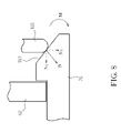
- FIG. 8 is a diagram of a first bolt pressing an inclined plane of a first wedging component according to the preferred embodiment of the present invention.
- FIG. 1 is a drawing of an electric device 50 according to a preferred embodiment of the present invention.
- the electric device 50 can be a portable computer, such as a notebook computer.
- the electric device 50 includes a host 52 including a housing 54 for covering the internal elements.
- FIG. 1 and FIG. 2 is a drawing of the housing 54 according to the preferred embodiment of the present invention.
- the housing 54 includes a framework 56 , and a lower casing 58 for covering the framework 56 .
- An opening 60 , a first fixing component 62 , and a second fixing component 64 are disposed on the framework 56 .
- the first fixing component 62 and the second fixing component 64 can be a rib structure respectively.
- the electric device 50 further includes a removable module 70 which can be a storage module, such as a hard disc drive or an optical disk drive.
- the electric device 50 further includes a fixing mechanism 72 for fixing the removable module 70 .
- the fixing mechanism 72 further includes a frame 74 for fixing the removable module 70 .
- the frame 74 is installed inside the housing 54 through the opening 60 in a detachable manner so that a user can draw the removable module 70 by pulling the frame 74 . Please refer to FIG. 3 .
- FIG. 3 is a drawing of the frame 74 according to the preferred embodiment of the present invention.
- a first wedging component 76 and a second wedging component 78 are disposed on the frame 74 and can be a hook respectively.
- the first wedging component 76 and the second wedging component 78 are used to wedge with the first fixing component 62 and the second fixing component 64 respectively for fixing the removable module 70 inside the housing 54 .
- An inclined plane 761 and an inclined plane 781 are formed on free ends of the first wedging component 76 and the second wedging component 78 respectively.
- the fixing mechanism 72 includes a releasing component 80 including a first releasing button 82 and a second releasing button 84 .
- the first releasing button 82 and the second releasing button 84 are installed inside the first hole 66 and the second hole 68 respectively.
- FIG. 4 is a drawing of the first releasing button 82 according to the preferred embodiment of the present invention.
- FIG. 5 is a sectional view of the first releasing button 82 wedging inside the first hole 66 according to the preferred embodiment of the present invention.
- FIG. 6 is a drawing of the frame 74 installed inside the housing 54 according to the preferred embodiment of the present invention.
- FIG. 7 is a drawing of the releasing component 80 combining with the frame 74 according to the preferred embodiment of the present invention.
- the first releasing button 82 and the second releasing button 84 include a first bolt 821 and a second bolt 841 respectively for pressing the inclined plane 761 of the first wedging component 76 and the inclined plane 781 of the second wedging component 78 respectively so that the first wedging component 76 and the second wedging component 78 deform respectively.
- the first releasing button 82 and the second releasing button 84 further include a first dome 822 and a second dome 842 respectively for connecting to a first bolt 821 and a second bolt 841 respectively so as to provide the user to press the first releasing button 82 and the second releasing button 84 .
- the first releasing button 82 further includes a first elastic element 823 , and a plurality of the first hooks 824 .
- the second releasing button 84 further includes a second elastic element 843 , and a plurality of the second hooks 844 .
- the first elastic element 823 and the second elastic element 843 are sheathed with the first bolt 821 and the second bolt 841 respectively.
- the plurality of the first hooks 824 and the plurality of the second hooks 844 are installed on the first bolt 821 and the second bolt 841 respectively for fixing the first elastic element 823 and the second elastic element 843 respectively.
- the first elastic element 823 and the second elastic element 843 can be a spring respectively.
- the first hook 824 and the second hook 844 can be an elastic structure respectively for wedging inside the first hole 66 and the second hole 68 elastically.
- the structures and working principles of the first releasing button 82 and the second releasing button 84 are the same, and the single releasing button is introduced herein for simplicity.
- the first hook 824 is an elastic structure, so the plurality of the first hooks 824 of the first releasing button 82 can be pressed inwardly so that the first elastic element 823 is sheathed with the plurality of the first hooks 824 for connecting to one side of the first bolt 821 . While the plurality of the first hooks 824 are released, the plurality of the first hooks 824 restores outwardly to an original position elastically so that the elastic restoring force can wedge the first elastic element 823 around the first bolt 821 tightly.
- the plurality of the first hooks 824 of the first releasing button 82 is pressed inward again for sheathing inside the first hole 66 so that free ends of the plurality of the first hooks 824 (wedging part) can pass through the first hole 66 .
- the plurality of the first hooks 824 restores outwardly to the original position elastically after the free ends of the plurality of the first hooks 824 pass through the first hole 66 so that the first releasing button 82 wedges inside the first hole 66 elastically.
- the first releasing button 82 and the second releasing button 84 can not press the inclined plane 761 of the first wedging component 76 and the inclined plane 781 of the second wedging component 78 respectively. It means the first wedging component 76 and the second wedging component 78 are not deformed.
- the user wants to draw the removable module 70 from the housing 52 the user has to press the first releasing button 82 and the second releasing button 84 down simultaneously.
- FIG. 8 is a diagram of the first bolt 821 pressing the inclined plane 761 of the first wedging component 76 according to the preferred embodiment of the present invention. While the first bolt 821 presses the inclined plane 761 of the first wedging component 76 , the first bolt 821 applies a normal force N on the inclined plane 761 of the first wedging component 76 .
- the normal force N is decomposed into two components of N X and N Y .
- the component of N Y generates a rotating moment M so that the first wedging component 76 deforms relative to a fixed end, then the first wedging component 76 departs from the first fixing component 62 .
- the second wedging component 78 departs from the second fixing component 64 so as to release constraint between the frame 74 and the housing 54 .
- the user can draw the frame 74 for drawing the removable module 70 out.
- the releasing component 80 of the fixing mechanism 72 of the present invention can also include a single releasing button structure. It means that the user only needs to press single releasing button for releasing the constraint of the frame 74 .
- the advantage of using the plurality of releasing buttons can avoid releasing the constrain of the frame 74 accidentally while touching single releasing button unintentionally so as to take out the removable module recklessly.
- the fixing mechanism with the plurality of releasing buttons can solve the above-mentioned problem by pressing all of the plurality of releasing buttons at the same time for releasing the constraint of the frame 74 .
- the releasing component 80 of the fixing mechanism 72 of the present invention can also be designed as a structure of single releasing button which is connected to the plurality of bolts for pressing the plurality of wedging components simultaneously. That is, the user presses a single releasing button for releasing the combination between the plurality of wedging components of the frame and the plurality of fixing components of the housing.
- the working principle is the same as the one of the above-mentioned embodiment, and hereby the detailed description is omitted for simplicity.
- the fixing mechanism of the present invention is capable of fixing the hard disc drive on the housing without utilizing screws.
- the present invention not only reduces the difficulty in assembly but also saves the labor hour and the cost of assembly components so as to promote convenience of assembly widely.
Abstract
Description
Claims (42)
Applications Claiming Priority (3)
| Application Number | Priority Date | Filing Date | Title |
|---|---|---|---|
| TW97214148U | 2008-08-07 | ||
| TW097214148U TWM351586U (en) | 2008-08-07 | 2008-08-07 | Fixing mechanism for fixing a removable module of an electronic device |
| TW097214148 | 2008-08-07 |
Publications (2)
| Publication Number | Publication Date |
|---|---|
| US20100033919A1 US20100033919A1 (en) | 2010-02-11 |
| US8027159B2 true US8027159B2 (en) | 2011-09-27 |
Family
ID=41652745
Family Applications (1)
| Application Number | Title | Priority Date | Filing Date |
|---|---|---|---|
| US12/464,112 Expired - Fee Related US8027159B2 (en) | 2008-08-07 | 2009-05-12 | Fixing mechanism for fixing a removable module of an electronic device |
Country Status (2)
| Country | Link |
|---|---|
| US (1) | US8027159B2 (en) |
| TW (1) | TWM351586U (en) |
Cited By (2)
| Publication number | Priority date | Publication date | Assignee | Title |
|---|---|---|---|---|
| US20110050056A1 (en) * | 2009-08-25 | 2011-03-03 | Wistron Corporation | Housing for an electronic device |
| US20120274191A1 (en) * | 2011-04-26 | 2012-11-01 | Hon Hai Precision Industry Co., Ltd. | Computer enclosure with securing member |
Families Citing this family (4)
| Publication number | Priority date | Publication date | Assignee | Title |
|---|---|---|---|---|
| TWI446862B (en) * | 2011-12-16 | 2014-07-21 | Wistron Corp | Fixing mechanism for fixing a data storage device and data storage module therewith |
| CN103853273A (en) * | 2012-11-30 | 2014-06-11 | 纬创资通股份有限公司 | Electronic device and detachable component thereof |
| TWI568334B (en) * | 2015-09-18 | 2017-01-21 | 技嘉科技股份有限公司 | Assembling fastener and mother board assembly |
| CN106547312B (en) * | 2015-09-18 | 2019-08-30 | 技嘉科技股份有限公司 | Assembling fastener and motherboard component |
Citations (16)
| Publication number | Priority date | Publication date | Assignee | Title |
|---|---|---|---|---|
| US2722579A (en) * | 1952-06-05 | 1955-11-01 | Applic Mach Motrices | Push-buttons |
| US4286132A (en) * | 1980-04-18 | 1981-08-25 | Greenwald Electro-Mechanical Consultants, Inc. | Snap-action switch |
| USD316853S (en) * | 1989-01-13 | 1991-05-14 | Product R&D Corporation | Computer peripheral enclosure |
| US5130892A (en) * | 1989-10-31 | 1992-07-14 | Kabushiki Kaisha Toshiba | Portable electronic device with battery pack retained by a spring-loaded slider unit |
| US5363273A (en) * | 1992-07-27 | 1994-11-08 | Ma Hsi K | Computer system with removable floppy disk drive and expansion slot assembly mounted flush in one corner |
| US5452179A (en) * | 1989-10-20 | 1995-09-19 | Kabushiki Kaisha Toshiba | Portable electronic apparatus having two disk drives mounted on a single fixing member |
| USD368258S (en) * | 1994-08-23 | 1996-03-26 | Zenith Data Systems Corporation | Combined portable battery charger cradle and floppy disk drive case |
| US5506749A (en) * | 1993-07-26 | 1996-04-09 | Kabushiki Kaisha Toshiba | Portable data-processing system having a removable battery pack replaceable with a second larger battery pack having a cylindrical member usable as a hand grip |
| US5761030A (en) * | 1996-06-19 | 1998-06-02 | Compaq Computer Corporation | Electronic device with circuit board latching and retaining structure |
| US6137685A (en) * | 1997-09-01 | 2000-10-24 | Funai Electric Co., Ltd | Portable electronic information device |
| US6606241B2 (en) * | 2001-06-29 | 2003-08-12 | Hewlett-Packard Development Company, L.P. | Ejection bay structure for portable computers |
| US20040125554A1 (en) * | 2001-08-14 | 2004-07-01 | Deluga Ronald E. | Latch assembly that facilitates the insertion and removal of a battery module from an electronic device |
| US20070001559A1 (en) * | 2005-07-02 | 2007-01-04 | Hon Hai Precision Industry Co., Ltd. | Computer enclosure with locking device |
| US7173815B2 (en) * | 2002-06-25 | 2007-02-06 | Samsung Electronics Co., Ltd. | Receiving unit for computer |
| US20090290304A1 (en) * | 2008-05-21 | 2009-11-26 | Shenzhen Futaihong Precision Industry Co., Ltd. | Battery cover latch mechanism and portable electronic device using same |
| US20090290303A1 (en) * | 2008-05-23 | 2009-11-26 | Shenzhen Futaihong Precision Industry Co., Ltd. | Battery cover latch mechanism and portable electronic device using same |
-
2008
- 2008-08-07 TW TW097214148U patent/TWM351586U/en not_active IP Right Cessation
-
2009
- 2009-05-12 US US12/464,112 patent/US8027159B2/en not_active Expired - Fee Related
Patent Citations (16)
| Publication number | Priority date | Publication date | Assignee | Title |
|---|---|---|---|---|
| US2722579A (en) * | 1952-06-05 | 1955-11-01 | Applic Mach Motrices | Push-buttons |
| US4286132A (en) * | 1980-04-18 | 1981-08-25 | Greenwald Electro-Mechanical Consultants, Inc. | Snap-action switch |
| USD316853S (en) * | 1989-01-13 | 1991-05-14 | Product R&D Corporation | Computer peripheral enclosure |
| US5452179A (en) * | 1989-10-20 | 1995-09-19 | Kabushiki Kaisha Toshiba | Portable electronic apparatus having two disk drives mounted on a single fixing member |
| US5130892A (en) * | 1989-10-31 | 1992-07-14 | Kabushiki Kaisha Toshiba | Portable electronic device with battery pack retained by a spring-loaded slider unit |
| US5363273A (en) * | 1992-07-27 | 1994-11-08 | Ma Hsi K | Computer system with removable floppy disk drive and expansion slot assembly mounted flush in one corner |
| US5506749A (en) * | 1993-07-26 | 1996-04-09 | Kabushiki Kaisha Toshiba | Portable data-processing system having a removable battery pack replaceable with a second larger battery pack having a cylindrical member usable as a hand grip |
| USD368258S (en) * | 1994-08-23 | 1996-03-26 | Zenith Data Systems Corporation | Combined portable battery charger cradle and floppy disk drive case |
| US5761030A (en) * | 1996-06-19 | 1998-06-02 | Compaq Computer Corporation | Electronic device with circuit board latching and retaining structure |
| US6137685A (en) * | 1997-09-01 | 2000-10-24 | Funai Electric Co., Ltd | Portable electronic information device |
| US6606241B2 (en) * | 2001-06-29 | 2003-08-12 | Hewlett-Packard Development Company, L.P. | Ejection bay structure for portable computers |
| US20040125554A1 (en) * | 2001-08-14 | 2004-07-01 | Deluga Ronald E. | Latch assembly that facilitates the insertion and removal of a battery module from an electronic device |
| US7173815B2 (en) * | 2002-06-25 | 2007-02-06 | Samsung Electronics Co., Ltd. | Receiving unit for computer |
| US20070001559A1 (en) * | 2005-07-02 | 2007-01-04 | Hon Hai Precision Industry Co., Ltd. | Computer enclosure with locking device |
| US20090290304A1 (en) * | 2008-05-21 | 2009-11-26 | Shenzhen Futaihong Precision Industry Co., Ltd. | Battery cover latch mechanism and portable electronic device using same |
| US20090290303A1 (en) * | 2008-05-23 | 2009-11-26 | Shenzhen Futaihong Precision Industry Co., Ltd. | Battery cover latch mechanism and portable electronic device using same |
Cited By (4)
| Publication number | Priority date | Publication date | Assignee | Title |
|---|---|---|---|---|
| US20110050056A1 (en) * | 2009-08-25 | 2011-03-03 | Wistron Corporation | Housing for an electronic device |
| US8322801B2 (en) * | 2009-08-25 | 2012-12-04 | Wistron Corporation | Housing for an electronic device |
| US20120274191A1 (en) * | 2011-04-26 | 2012-11-01 | Hon Hai Precision Industry Co., Ltd. | Computer enclosure with securing member |
| US8596730B2 (en) * | 2011-04-26 | 2013-12-03 | Hong Fu Jin Precision Industry (Wuhan) Co., Ltd. | Computer enclosure with securing member |
Also Published As
| Publication number | Publication date |
|---|---|
| US20100033919A1 (en) | 2010-02-11 |
| TWM351586U (en) | 2009-02-21 |
Similar Documents
| Publication | Publication Date | Title |
|---|---|---|
| US8027159B2 (en) | Fixing mechanism for fixing a removable module of an electronic device | |
| US8199476B2 (en) | Notebook computer | |
| US8081480B2 (en) | Fixing module and case having the fixing module | |
| TWI423760B (en) | Fixing mechanism for fixing a board and electronic device therewith | |
| US6744622B2 (en) | Slidable cover mechanism for main unit | |
| US7835148B2 (en) | Portable storage device capable of being disassembled easily | |
| US8247690B2 (en) | Housing for electronic device | |
| US20050174734A1 (en) | Heat dissipation device and fan module thereof | |
| CN101930782B (en) | Hard disk fixing mechanism and electronic device provided with same | |
| US7200002B2 (en) | Connection port module | |
| TWI511657B (en) | Fixing struture and electronic device therewith | |
| US20140139997A1 (en) | Installation structure of data storage device and data storage system using the same | |
| TWI442216B (en) | Keyboard fixing structure for fixing a keyboard and portable electronic device using the same | |
| US6997635B2 (en) | Latch structure for removably mounting a side panel of an electronic product | |
| US20130170130A1 (en) | Electronic apparatus and carrying structure thereof | |
| US8223491B2 (en) | Fastener for securing computer storage device | |
| CN101599375B (en) | Press key fixing device | |
| US20120044654A1 (en) | Fixing mechanism for fixing a removable module and related electronic device | |
| US20130277513A1 (en) | Hard disk bracket | |
| US20160091136A1 (en) | Detachable fixing mechanism and related electronic device | |
| US7948745B2 (en) | Release module and computer housing using the same | |
| US20120282016A1 (en) | Fixing mechanism for fixing at least one interface card and fixing rod thereof | |
| US7724506B2 (en) | Electronic device | |
| US20130134848A1 (en) | Casing of mobile device | |
| TWI732340B (en) | Fastening structure |
Legal Events
| Date | Code | Title | Description |
|---|---|---|---|
| AS | Assignment |
Owner name: WISTRON CORPORATION,TAIWAN Free format text: ASSIGNMENT OF ASSIGNORS INTEREST;ASSIGNORS:YU, LIANG;CHUANG, CHENG-HSIANG;REEL/FRAME:022667/0791 Effective date: 20090510 Owner name: WISTRON CORPORATION, TAIWAN Free format text: ASSIGNMENT OF ASSIGNORS INTEREST;ASSIGNORS:YU, LIANG;CHUANG, CHENG-HSIANG;REEL/FRAME:022667/0791 Effective date: 20090510 |
|
| ZAAA | Notice of allowance and fees due |
Free format text: ORIGINAL CODE: NOA |
|
| ZAAB | Notice of allowance mailed |
Free format text: ORIGINAL CODE: MN/=. |
|
| STCF | Information on status: patent grant |
Free format text: PATENTED CASE |
|
| FPAY | Fee payment |
Year of fee payment: 4 |
|
| MAFP | Maintenance fee payment |
Free format text: PAYMENT OF MAINTENANCE FEE, 8TH YEAR, LARGE ENTITY (ORIGINAL EVENT CODE: M1552); ENTITY STATUS OF PATENT OWNER: LARGE ENTITY Year of fee payment: 8 |
|
| FEPP | Fee payment procedure |
Free format text: MAINTENANCE FEE REMINDER MAILED (ORIGINAL EVENT CODE: REM.); ENTITY STATUS OF PATENT OWNER: LARGE ENTITY |
|
| LAPS | Lapse for failure to pay maintenance fees |
Free format text: PATENT EXPIRED FOR FAILURE TO PAY MAINTENANCE FEES (ORIGINAL EVENT CODE: EXP.); ENTITY STATUS OF PATENT OWNER: LARGE ENTITY |
|
| STCH | Information on status: patent discontinuation |
Free format text: PATENT EXPIRED DUE TO NONPAYMENT OF MAINTENANCE FEES UNDER 37 CFR 1.362 |
|
| FP | Lapsed due to failure to pay maintenance fee |
Effective date: 20230927 |