US802496A - Steam-pressure-reducing valve. - Google Patents
Steam-pressure-reducing valve. Download PDFInfo
- Publication number
- US802496A US802496A US1904252918A US802496A US 802496 A US802496 A US 802496A US 1904252918 A US1904252918 A US 1904252918A US 802496 A US802496 A US 802496A
- Authority
- US
- United States
- Prior art keywords
- valve
- chamber
- pressure
- steam
- casing
- Prior art date
- Legal status (The legal status is an assumption and is not a legal conclusion. Google has not performed a legal analysis and makes no representation as to the accuracy of the status listed.)
- Expired - Lifetime
Links
Images

Classifications
-
- F—MECHANICAL ENGINEERING; LIGHTING; HEATING; WEAPONS; BLASTING
- F16—ENGINEERING ELEMENTS AND UNITS; GENERAL MEASURES FOR PRODUCING AND MAINTAINING EFFECTIVE FUNCTIONING OF MACHINES OR INSTALLATIONS; THERMAL INSULATION IN GENERAL
- F16K—VALVES; TAPS; COCKS; ACTUATING-FLOATS; DEVICES FOR VENTING OR AERATING
- F16K17/00—Safety valves; Equalising valves, e.g. pressure relief valves
- F16K17/02—Safety valves; Equalising valves, e.g. pressure relief valves opening on surplus pressure on one side; closing on insufficient pressure on one side
- F16K17/04—Safety valves; Equalising valves, e.g. pressure relief valves opening on surplus pressure on one side; closing on insufficient pressure on one side spring-loaded
- F16K17/10—Safety valves; Equalising valves, e.g. pressure relief valves opening on surplus pressure on one side; closing on insufficient pressure on one side spring-loaded with auxiliary valve for fluid operation of the main valve
- F16K17/105—Safety valves; Equalising valves, e.g. pressure relief valves opening on surplus pressure on one side; closing on insufficient pressure on one side spring-loaded with auxiliary valve for fluid operation of the main valve using choking or throttling means to control the fluid operation of the main valve
-
- Y—GENERAL TAGGING OF NEW TECHNOLOGICAL DEVELOPMENTS; GENERAL TAGGING OF CROSS-SECTIONAL TECHNOLOGIES SPANNING OVER SEVERAL SECTIONS OF THE IPC; TECHNICAL SUBJECTS COVERED BY FORMER USPC CROSS-REFERENCE ART COLLECTIONS [XRACs] AND DIGESTS
- Y10—TECHNICAL SUBJECTS COVERED BY FORMER USPC
- Y10T—TECHNICAL SUBJECTS COVERED BY FORMER US CLASSIFICATION
- Y10T137/00—Fluid handling
- Y10T137/598—With repair, tapping, assembly, or disassembly means
- Y10T137/6154—With disassembly tool engaging feature
-
- Y—GENERAL TAGGING OF NEW TECHNOLOGICAL DEVELOPMENTS; GENERAL TAGGING OF CROSS-SECTIONAL TECHNOLOGIES SPANNING OVER SEVERAL SECTIONS OF THE IPC; TECHNICAL SUBJECTS COVERED BY FORMER USPC CROSS-REFERENCE ART COLLECTIONS [XRACs] AND DIGESTS
- Y10—TECHNICAL SUBJECTS COVERED BY FORMER USPC
- Y10T—TECHNICAL SUBJECTS COVERED BY FORMER US CLASSIFICATION
- Y10T137/00—Fluid handling
- Y10T137/7722—Line condition change responsive valves
- Y10T137/7758—Pilot or servo controlled
- Y10T137/7762—Fluid pressure type
- Y10T137/7764—Choked or throttled pressure type
- Y10T137/7766—Choked passage through main valve head
-
- Y—GENERAL TAGGING OF NEW TECHNOLOGICAL DEVELOPMENTS; GENERAL TAGGING OF CROSS-SECTIONAL TECHNOLOGIES SPANNING OVER SEVERAL SECTIONS OF THE IPC; TECHNICAL SUBJECTS COVERED BY FORMER USPC CROSS-REFERENCE ART COLLECTIONS [XRACs] AND DIGESTS
- Y10—TECHNICAL SUBJECTS COVERED BY FORMER USPC
- Y10T—TECHNICAL SUBJECTS COVERED BY FORMER US CLASSIFICATION
- Y10T137/00—Fluid handling
- Y10T137/7722—Line condition change responsive valves
- Y10T137/7758—Pilot or servo controlled
- Y10T137/7762—Fluid pressure type
- Y10T137/7764—Choked or throttled pressure type
- Y10T137/7767—Loose fitting piston
Definitions
- Patented 0a. 2a, 1905 Patented 0a. 2a, 1905.
- Fig. 2 is a transversc cross-section taken on line it 2 ofl ig. 1.
- Fig. 3 is a central vertical section somewhat similar to Fig. 1, but showing a slightly-modilicd form of my in- Vention.
- My device comprises asuit' able casing in which the main-valve body, with its several elements, and the auxiliary valve are held in their respective chambers and operated through the medium of a diaphragm.
- This diaphrz-igm is operated by the system-pressure and is. provided with a spring and means for regulating the tension of said spring against said diaphragm.
- the whole device is constructed in a way to allow free access to the valve mechanism in case inspection or repairs are desired, and likewise to in sure perfect drainage.
- A indicates the main casing of the valve, which, as shown, is provided with an inlet-nipple A, and a coupling B for connection to the locomotive or ini tial pressure, and an outlctmipple with a coupling B for connection with the heating system, as is obviously necessary.
- C indicates a body, the bottom of which forms a valve to contact with a valve-scat l) of the casing A.
- the upper part of the body forms a reciprocating piston I), that loosely engages the bore (1 of the casing in a way to admit a slight passage ofsteain thereby, and the lower end 01'' the body contains a stem that engages a guide-lug l of the casing.
- a cushion-chamber G and a supplementary regulating-port H to receive the plunger G on the depending stem of the valvc-body C, which plunger enters the port H of the casing in a way to loosely close the same.
- the top of the bore of the casing is closed by a plug F,' ⁇ vhich projects downward in reduced size, forming a hub F, upon which a spring E is clamped and which extends to the bottom of the hollow valve-body U for its engagement.
- a hook By inserting a hook into eye V of the valve-body C the same and spring can be lifted out of the bore, allowing free access to the interior oi the casing, there being but two elements the plug l5" and valve-body (1 to disassemble and assci'nble in case cleaning is necessary.
- the steam-passage S connects the chamber F above the piston l) to the service system through auxiliary val vc J and allowing the steam which escapes by the piston D from valve-chai'nber E to the chamber F to enter the service system when auxiliary valve J is open in a way to insure an equal pressure in chamber is and the low-pressure side of the device when the auxiliary valve is open.
- the auxiliary valve J is for the purpose of governing the pressure in the chamber F above the piston l) and is grooved to allow steam to pass when open. it is horizontally chambered in the casing, as seen in Fig. 1, and has a stem on both ends.
- the stem J" extends through a guide L in plug 5 and into a hub U, which tionally hold the ad ustir min is pressed inward by spring M.
- the guide L is pinned into the plug (3, making a permanent assembly of the elements which are chambered l therein so they can be removed and handled as it but one piece.
- the inner stem J extends across the barrel and through hole in the 1 opposite wall 0? the casing and into the diaphlegm-chamber against diaphragm L.
- the auxiliary valve J is entirely separated from the main valve and can be removed from its chamber and cleaned should it become foul and fail to properly operate.
- this spring is engaged by nut P, which has ears P to engage grooves in the sleeve of the bonnet to prevent its turning.
- This nut is adjusted to and from the diaphragm by means of an adjusting screw Q, which is journaled'in cap Q, threadably attached to the sleeve of bonnet N.
- the outer end of the adjusting-screw C3 is attached a hand-wheel R, by means oi? which the screw is turned to adjust the pressure of nut l? on the regulating-spring M.
- friction springndisk R is interposed in a pocliet of the cap Q" and between the same and the wheel R and clamped between them by screw Y, which is set into the squared end of the barrel of the adjusting-screw Q,- io'cing the wheel it down to its place and spreading the spring-dist R in a way to fric- -screw Q and wheel it in their adjusted positions.
- Fig. 3 it will be seen that the construction therein shown diilers but slightly from that disclosedin Figs. 1 and 2 so far as its practical operation is concerned. the principal difference in construction being the lo cation of the diaphragm, its bonnet, and adjusting mechanism, which, as shown in Fig. 3, located at the bottom ot' the valve-cas inn, while 51g. 1 it is locatn l at the side oi .the valvew sing.
- the location of the auxiliary v yo J is also dilierent, being anged vertically and directly beneath the guide-stem ii of the valve-body C.
- the upper stem J of this valve extends centrally through the S of the valve-body and into the spring-actuated hub U, housed in a suitable recess ot pluu; F.
- the plug 15" By removing the plug 15" the s. li' and the i is inciosed by the guide ii can'be removed togetheigand by takholu or auxiliary-valve stem J" he mainscenes valve body and the auxiliary valve can be drawn from the casing, thus removing the entire valve mechanism and leaving the intetier of the casing freet'or inspection or cleaning.
- the passage S" takes the place of the passage S in the Wall of the main casing (shown in Fig. l) and furnishes an outlet between chamber F and the low-pressure side of the casing when auxiliary valve J is open.
- the plunger Gr (shown in Fig. 3) is made detachable to permit its removal, if desirable.
- the piston D on valve-body G as shown in Fig. 3, is provided with steam-packingT and a small port T through the C to permit the initial steam from valve-chamber E to enter chamber F and exert apressure on piston D when auxiliary valve J is closed.
- valve-chamber E the pressure,act inp
- piston D forces valve-body C upward, lifting the valve from its seat D against the spring E, which has no pressure on the valve-body when the valve is in a closed position and is only to prevent a too-violent lifting of the valve-body when the steam is first admitted to chamber E.
- a steam-pressure-reducing valve com prising a casing having a high-pressure chamber an auxiliary-valve chamber and a diaphragm chamber, and containing a mainvalve body, an auxiliary valve and a diaphragm each respectively located in said separate and independent compartments of the casing in a way to permit any one of them to be removed and replaced Without disturbing the others, and suitable ports connecting said valves and diaphragm.
- a steanrpressure-reducing valve the combination with a valve-casing, containing a main-valve chamber, an auxiliary-valve chamber, and ports connecting the same, of a valvebody in the first-named chamber, an auxiliary valve in the second-named chamber, a diaphragm and chamber thereini and means to allow the removal of each or any of said ports without disturbing the others.
- a steam-pressure-regulating valve the combination with a casing containing a valve chamber and seat, and a cushion-chamber and port, of a body movably mounted in said chambers bearing a main valve to engage said seatand a plunger to close the port of the cushionchamber, said valve and plunger being so proportioned and arranged with. relation-to said seat and port that the said seat is opened in advance of the port with the rise of the body.
- valve-body intermediate of said inlet and outlet, a cushion-chamber having an outlet to the system, a plunger attached to said body adapted to close the outlet, said val ve and plunger being so located and proportioned with relation to each other that the valve opens in advance of the plunger in a way to prevent the cutting of the valve-seat substantially as described.
- a-casing provided with a valve-seat, of a body mounted therein, a cfisln ion-chamber below the body having ,an outlet-port, a plunger. carried by the body adapted to fit said outlet-port, said plunger and seat being so proportioned and arranged with relation to each other that .the valve is opened in advance of the outlet port in a way to first fill the cushion-chamber to check the flow ol steam and prevent the cutting of the valve.
- a steam-pressure-reducing valve the combination with a casing, a body bearing a piston, an inlet and chamber below the piston, a chamber above the piston, a passage through the body intermediate of said chambers, a cushion-chamber below the body, a plunger connected with the body to open and close an outlet-port of said cushion-chamber and means for automatically operating the body with the varying pressure in the system in amanner to open and close said port.
- a steam-pressure-red ucing valve the combination with a casing, of a valve-body, fitted therein provided with a piston, seat and plunger, a cushion-chamber intermediate of the seat and plunger, a diaphragm, an auxiliary valve operated by the diaphragm, ports leading from said auxiliary valve to a ehamber above the valve-body and to the systemoutlet whereby the initial flow of steam to the system is controlled and whereby the pressure upon the top side of the body is increased or decreased to open and close the same.
- a steampressurereducing valve the combination with a casing of a movable valvebody fitted therein bearing a piston, a chamber above and below said piston, a cushionchambr below the body, an outlet for said cushion-chamber, a plunger attached to the body in a way to open and close the outlet from the cushion-chamber to the system with the movement of the body, a diaphragm operated by the system-pressure, an auxiliary valve controlled by said diaphragm, a port leading from the chamber above the body to the lowpressure side of the valve in a way to control the initial flow of steam from said chamber to said low-pressure side.
- a,steam-pressure-reducing valve the combination with a casing, of a bodyinovablv mounted therein hearing a piston and ports, a ehaniher above and below the piston, a seat and means for normally holding the bod v down upon said seat, a steam-passage leading from the upper chamber to the lOW-JYGSSUTG side of the valve, an auxiliary valve in said nassage to govern the initial flow of steam to the system, adiaphragin operated by the low pressure to control said auxiliary valve, a spring and means for adjusting the same to regulate the tension on the diaphragm.
Description
No. 802,496. PATENTED 00-1. 24, 1905. a. W." 00mm:
STEAM PREssUmE Rmmm VALVE. APPLIOATION FILED APE.22.1904. REIEEWED MAR. 30. 1905.
' QBHEETS-EEEET 1.
' 2 I QM'MMQQQ No. 802,496. PATENTED OCT. 24, 1905. G, HELLER I STEAM PRESSURE REDUCING VALVE.
APPLIOATION FILED APR. 22, 1904.v RENEWED MAR. 30. 1905.
- 2 sums-sum 2.
UNIT SAES Gnoaen W. ooLLiN,
UFIUE.
OF BRIDGEPORT, CONNECCITIOUTL no. season.
Specification of Letters Patent.
Patented 0a. 2a, 1905.
Application finaa rn 22, 1904. Renewed March 80, 1906' Serial No. 252,918.
To all, whom it may concern/.-
Be it known that I, GEORGE W. COLLIN, a citizen of the United Stateaand a resident of Bridgeport, in the county of Fair-field and State of Connecticut, have invented certain )roducin a reducin -valve which has a su plcmentary regulating-port between the main valve and the lower-pressure side, to regulate thoimovernent of the main valve in a manner to prevent its hammering or cl'iattering when opening or closing, and to provide means for so regulating the How of steam-that the valve will not be wire-drawn or cut by the steam, as will later be explained; finally, to provide a valve which consists in part of a main valve, an auxiliary valve, a diaphragm, and means for regulating the tension on the same, said valves being located in separate chambers of the valve-casing and independent from said diaphragm, soas to be removable w1thoutdxsturbing said diaphragm.
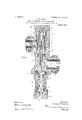
With the above objects in view my invention resides and consists in the novel construction and combination of parts shown upon the accompanying two sheets of drawings, forming a part of this specification, upon wliich similar characters of 1cfcrcnce lenote like or corresponding parts throughout the several figures, and oi which Figure 1 shows a vertical central sectional view through my improved valve complete.
Fig. 2 is a transversc cross-section taken on line it 2 ofl ig. 1. Fig. 3 is a central vertical section somewhat similar to Fig. 1, but showing a slightly-modilicd form of my in- Vention.
My device, as will be seen, comprises asuit' able casing in which the main-valve body, with its several elements, and the auxiliary valve are held in their respective chambers and operated through the medium of a diaphragm. This diaphrz-igm is operated by the system-pressure and is. provided with a spring and means for regulating the tension of said spring against said diaphragm. The whole device is constructed in a way to allow free access to the valve mechanism in case inspection or repairs are desired, and likewise to in sure perfect drainage.
Referring in detail to the characters of rel"- ercnce marked upon the drawings, and more especially to Figs. 1 and 2, A indicates the main casing of the valve, which, as shown, is provided with an inlet-nipple A, and a coupling B for connection to the locomotive or ini tial pressure, and an outlctmipple with a coupling B for connection with the heating system, as is obviously necessary. C indicates a body, the bottom of which forms a valve to contact with a valve-scat l) of the casing A. The upper part of the body forms a reciprocating piston I), that loosely engages the bore (1 of the casing in a way to admit a slight passage ofsteain thereby, and the lower end 01'' the body contains a stem that engages a guide-lug l of the casing. Below the valvcseat D is formed a cushion-chamber G and a supplementary regulating-port H to receive the plunger G on the depending stem of the valvc-body C, which plunger enters the port H of the casing in a way to loosely close the same. The top of the bore of the casing is closed by a plug F,'\vhich projects downward in reduced size, forming a hub F, upon which a spring E is clamped and which extends to the bottom of the hollow valve-body U for its engagement. By inserting a hook into eye V of the valve-body C the same and spring can be lifted out of the bore, allowing free access to the interior oi the casing, there being but two elements the plug l5" and valve-body (1 to disassemble and assci'nble in case cleaning is necessary. The steam-passage S connects the chamber F above the piston l) to the service system through auxiliary val vc J and allowing the steam which escapes by the piston D from valve-chai'nber E to the chamber F to enter the service system when auxiliary valve J is open in a way to insure an equal pressure in chamber is and the low-pressure side of the device when the auxiliary valve is open. The auxiliary valve J is for the purpose of governing the pressure in the chamber F above the piston l) and is grooved to allow steam to pass when open. it is horizontally chambered in the casing, as seen in Fig. 1, and has a stem on both ends. The stem J" extends through a guide L in plug 5 and into a hub U, which tionally hold the ad ustir min is pressed inward by spring M. The guide L is pinned into the plug (3, making a permanent assembly of the elements which are chambered l therein so they can be removed and handled as it but one piece. The inner stem J extends across the barrel and through hole in the 1 opposite wall 0? the casing and into the diaphlegm-chamber against diaphragm L. As here shown, the auxiliary valve J is entirely separated from the main valve and can be removed from its chamber and cleaned should it become foul and fail to properly operate. This is accomplished by first removing plug S, taking hold of the stem J", and drawing the valve out of its chan'iber, which exposes the valve-seat near the surface so as to be readily cleaned. 'ihe uiaphragm chamber N is separated from the barrel of the casing, except by the drilled passages for the valve-stem J and the lower passage L" for steam-inlet and drainage-outlet. The diaphragm is clamped between the threaded hub N and the bonnet i l. The presseuhub N is interposed between the said diaphragm L and the spring M, which is housed within the sleeve of the bonnet. The opposite end of this spring is engaged by nut P, which has ears P to engage grooves in the sleeve of the bonnet to prevent its turning. This nut is adjusted to and from the diaphragm by means of an adjusting screw Q, which is journaled'in cap Q, threadably attached to the sleeve of bonnet N. the outer end of the adjusting-screw C3 is attached a hand-wheel R, by means oi? which the screw is turned to adjust the pressure of nut l? on the regulating-spring M. A. friction springndisk R is interposed in a pocliet of the cap Q" and between the same and the wheel R and clamped between them by screw Y, which is set into the squared end of the barrel of the adjusting-screw Q,- io'cing the wheel it down to its place and spreading the spring-dist R in a way to fric- -screw Q and wheel it in their adjusted positions.
Referring to Fig. 3, it will be seen that the construction therein shown diilers but slightly from that disclosedin Figs. 1 and 2 so far as its practical operation is concerned. the principal difference in construction being the lo cation of the diaphragm, its bonnet, and adjusting mechanism, which, as shown in Fig. 3, located at the bottom ot' the valve-cas inn, while 51g. 1 it is locatn l at the side oi .the valvew sing. The location of the auxiliary v yo J is also dilierent, being anged vertically and directly beneath the guide-stem ii of the valve-body C. The upper stem J of this valve extends centrally through the S of the valve-body and into the spring-actuated hub U, housed in a suitable recess ot pluu; F. By removing the plug 15" the s. li' and the i is inciosed by the guide ii can'be removed togetheigand by takholu or auxiliary-valve stem J" he mainscenes valve body and the auxiliary valve can be drawn from the casing, thus removing the entire valve mechanism and leaving the intetier of the casing freet'or inspection or cleaning. The passage S" takes the place of the passage S in the Wall of the main casing (shown in Fig. l) and furnishes an outlet between chamber F and the low-pressure side of the casing when auxiliary valve J is open.
The plunger Gr (shown in Fig. 3) is made detachable to permit its removal, if desirable. The piston D on valve-body G, as shown in Fig. 3, is provided with steam-packingT and a small port T through the C to permit the initial steam from valve-chamber E to enter chamber F and exert apressure on piston D when auxiliary valve J is closed.
As previously stated, the operation of the two constructions are precisely the same and substantially as follows: When the steam is admitted to valve-chamber E,the pressure,act inp; on the lower side of piston D, forces valve-body C upward, lifting the valve from its seat D against the spring E, which has no pressure on the valve-body when the valve is in a closed position and is only to prevent a too-violent lifting of the valve-body when the steam is first admitted to chamber E. [With the opening of the main valve, as above set forth, steam is obviously free to enter the service system to the pressure desired, which when obtained causes the-valve to automatically operate and sustain said pressure in the following way: lVhen the pressurein the system reaches theheig ht desired, regulated by the pressure of springM on diaphragm L, said diaphragm isfpreed outward, releasing-"the auxiliary valve push the auxiliary valve J into its seat rcue ting off the escape of steam from chamber F to the system through the intefvening passage, causing the pressure to rise above the piston D until it overbalances the initialliftlug-pressure, forcing the valve-body C down. as the valve-body descends the plunger enters its port before said valve reaches its seat D, cutting on the free passage of steam,which being checked in cushion-chamber G forms a pressure-cushion below the valve, checking its descent. The pressure then rises in chamber F, overcoming this resistance and forces the valve to its seat Without hammering or chattering. The area of the bottom of the valve being greater than the area of the plunger gives a pressurecushion to the bottom of the valve, and with proportions of parts shown in the dra lugs there will be'a cushionresistance oi? eighty-eight pounds when the plunger G enters its port iiproviding theinitial pressure is two lumdred pounds. When the pres ure becomes reduced sufficient to allow the spring M to force the diaphragm L inward, the auxiliary-valve stem J is pushed back, opening the auxiliary valve J, allowing side of the body the I J and permitting spring M to soaaoe the steam-pressure in chamber 1 to escape to the system through passage S, and the initial i rcssure in valve-chamber E, acting on the lower side of the piston D, again lifts the valve-body, opening the main valve. When the valve begins to lift from its seat D, as above, steam enters the cushion-chamber G and will sustain the initial pressure therein so that there will be no velocity of steam through the valve until the plunger G is lifted from its port to allow af ee passage of steam to the system, at which time the valve will be so far above its seat that wire-drawing is impossible.
.ln this invention 1 do'not wish to belimited to the details of construction shown, since these can obviously be changed without departing from the essence of the invention. This is particularly true with reference to the location of the diaphragm or auxiliary valve and likewise the several features of the main valve and auxiliary chambers.
Having thus described my invention, what 1 claim, and desire to secure by Letters Pat out, is
1. A steam-pressure-reducing valve, com prising a casing having a high-pressure chamber an auxiliary-valve chamber and a diaphragm chamber, and containing a mainvalve body, an auxiliary valve and a diaphragm each respectively located in said separate and independent compartments of the casing in a way to permit any one of them to be removed and replaced Without disturbing the others, and suitable ports connecting said valves and diaphragm.
2. In a steanrpressure-reducing valve, the combination with a valve-casing, containing a main-valve chamber, an auxiliary-valve chamber, and ports connecting the same, of a valvebody in the first-named chamber, an auxiliary valve in the second-named chamber, a diaphragm and chamber thereini and means to allow the removal of each or any of said ports without disturbing the others.
3. In a steam-pressure-red ucing valve, the,
combination of a casing containing a mainvalve chamber and. body, an auxiliary-valve chamber, a diaphragm and chamber for the same, ports connecting said chambers, an auxiliary valve connected with the diaphragm in a way to be operated thereby to open and clo'se, means to permit the removal of either said valve, diaphragm or body independent of the others.
4. In a steam-pressure-regulating valve, the combination with a casing containing a valve chamber and seat, and a cushion-chamber and port, of a body movably mounted in said chambers bearing a main valve to engage said seatand a plunger to close the port of the cushionchamber, said valve and plunger being so proportioned and arranged with. relation-to said seat and port that the said seat is opened in advance of the port with the rise of the body.
5. In asteam-pressure-regulating valve, the
combination with a suitable casing bearing a high-pressure inlet and a low-pressure outlet, of a valve-body intermediate of said inlet and outlet, a cushion-chamber having an outlet to the system, a plunger attached to said body adapted to close the outlet, said val ve and plunger being so located and proportioned with relation to each other that the valve opens in advance of the plunger in a way to prevent the cutting of the valve-seat substantially as described.
6. In a steam-pressure-reducing valve, the combination with a-casing provided with a valve-seat, of a body mounted therein, a cfisln ion-chamber below the body having ,an outlet-port, a plunger. carried by the body adapted to fit said outlet-port, said plunger and seat being so proportioned and arranged with relation to each other that .the valve is opened in advance of the outlet port in a way to first fill the cushion-chamber to check the flow ol steam and prevent the cutting of the valve.
7. In a steam-pressure-reducing valve, the combination with a casing, a body bearing a piston, an inlet and chamber below the piston, a chamber above the piston, a passage through the body intermediate of said chambers, a cushion-chamber below the body, a plunger connected with the body to open and close an outlet-port of said cushion-chamber and means for automatically operating the body with the varying pressure in the system in amanner to open and close said port.
8. In a steam-pressure-red ucing valve, the combination with a casing, of a valve-body, fitted therein provided with a piston, seat and plunger, a cushion-chamber intermediate of the seat and plunger, a diaphragm, an auxiliary valve operated by the diaphragm, ports leading from said auxiliary valve to a ehamber above the valve-body and to the systemoutlet whereby the initial flow of steam to the system is controlled and whereby the pressure upon the top side of the body is increased or decreased to open and close the same.
9. In a steampressurereducing valve, the combination with a casing of a movable valvebody fitted therein bearing a piston, a chamber above and below said piston, a cushionchambr below the body, an outlet for said cushion-chamber, a plunger attached to the body in a way to open and close the outlet from the cushion-chamber to the system with the movement of the body, a diaphragm operated by the system-pressure, an auxiliary valve controlled by said diaphragm, a port leading from the chamber above the body to the lowpressure side of the valve in a way to control the initial flow of steam from said chamber to said low-pressure side.
10. [n a steam-pressure-reducing valve, the
combination with a casing bearing a highpressure inlet and a low-pressure outlet, of a body fitted within the casing bearinga piston, a chamber above and below the piston, a port in the body intermediate or eheniher, a seat for the body, a passage lee-ding; from upper chamber to the lUW-QFESSUTG outlet, an auxiliary valve intermediate of said passage, and means for automatically operating said auxiliary vaive to control the initial or ssur of steam from the high-pressure to the low-- pressure side of the valve.
11. in a,steam-pressure-reducing valve, the combination with a casing, of a bodyinovablv mounted therein hearing a piston and ports, a ehaniher above and below the piston, a seat and means for normally holding the bod v down upon said seat, a steam-passage leading from the upper chamber to the lOW-JYGSSUTG side of the valve, an auxiliary valve in said nassage to govern the initial flow of steam to the system, adiaphragin operated by the low pressure to control said auxiliary valve, a spring and means for adjusting the same to regulate the tension on the diaphragm.
12. lira steam-pressure-regulating valve, the oonnhin'ation with a casing, of body rnovahly mounted therein hearing a piston having steam-ports. a chamber beneath and above w the valve, an auxil l I, gs, a diaphragm for valve 1n one direction, tne same, a plug in which ts is slidahly mounted 1n stern of the wav permit of the removal of the. valve g t e detachment of the plum I 13. a steam-preSsure=reduoing valve, the combination with a casing, having an inlt ls and outlet, of a body bearing a piston, a chamber below the piston, an outlet from said chernheg chamber above the piston eonneeted with the inlet, a passage vfrom said chamber, connected with the outlet, an auxiliary valve in aid passage, a diaphragm for operating the auxiliary valve and means for regulating the tension of said diaphragrnl Signed at Bridgeport, in the county of Fairtield and State of Connecticut, this 20th day of Aprih ri. 1904. Y
GEORGE W. CGLLIN.
Witnesses:
C. il EWMAN,
W. V. Dnvlr'r.
l Ell leading from said nope!"
Priority Applications (1)
| Application Number | Priority Date | Filing Date | Title |
|---|---|---|---|
| US1904252918 US802496A (en) | 1904-04-22 | 1904-04-22 | Steam-pressure-reducing valve. |
Applications Claiming Priority (1)
| Application Number | Priority Date | Filing Date | Title |
|---|---|---|---|
| US1904252918 US802496A (en) | 1904-04-22 | 1904-04-22 | Steam-pressure-reducing valve. |
Publications (1)
| Publication Number | Publication Date |
|---|---|
| US802496A true US802496A (en) | 1905-10-24 |
Family
ID=2870979
Family Applications (1)
| Application Number | Title | Priority Date | Filing Date |
|---|---|---|---|
| US1904252918 Expired - Lifetime US802496A (en) | 1904-04-22 | 1904-04-22 | Steam-pressure-reducing valve. |
Country Status (1)
| Country | Link |
|---|---|
| US (1) | US802496A (en) |
Cited By (6)
| Publication number | Priority date | Publication date | Assignee | Title |
|---|---|---|---|---|
| US2523906A (en) * | 1943-12-28 | 1950-09-26 | Bendix Aviat Corp | Pressure breathing oxygen regulator |
| US2839077A (en) * | 1956-09-28 | 1958-06-17 | Alv B Kristensson | Pressure regulator assembly |
| US3002524A (en) * | 1957-04-29 | 1961-10-03 | Fairchild Stratos Corp | Full or partial flow regulating device |
| US3003516A (en) * | 1957-04-08 | 1961-10-10 | Granberg Corp | Flow control valve assembly |
| US3073338A (en) * | 1963-01-15 | Stelzer | ||
| US4083375A (en) * | 1976-02-18 | 1978-04-11 | Johnson Dwight N | Pilot regulator |
-
1904
- 1904-04-22 US US1904252918 patent/US802496A/en not_active Expired - Lifetime
Cited By (6)
| Publication number | Priority date | Publication date | Assignee | Title |
|---|---|---|---|---|
| US3073338A (en) * | 1963-01-15 | Stelzer | ||
| US2523906A (en) * | 1943-12-28 | 1950-09-26 | Bendix Aviat Corp | Pressure breathing oxygen regulator |
| US2839077A (en) * | 1956-09-28 | 1958-06-17 | Alv B Kristensson | Pressure regulator assembly |
| US3003516A (en) * | 1957-04-08 | 1961-10-10 | Granberg Corp | Flow control valve assembly |
| US3002524A (en) * | 1957-04-29 | 1961-10-03 | Fairchild Stratos Corp | Full or partial flow regulating device |
| US4083375A (en) * | 1976-02-18 | 1978-04-11 | Johnson Dwight N | Pilot regulator |
Similar Documents
| Publication | Publication Date | Title |
|---|---|---|
| US1046236A (en) | Means for obviating the vibrations of main pressure-actuated valves. | |
| US3495619A (en) | Reducing valve | |
| US802496A (en) | Steam-pressure-reducing valve. | |
| US693133A (en) | Automatic duplex check and stop valve. | |
| US836306A (en) | Reducing-valve. | |
| US868030A (en) | Valve. | |
| US1065615A (en) | Equalizing-valve for water. | |
| US824681A (en) | Pressure-regulator. | |
| US620829A (en) | batchelor | |
| US1196925A (en) | Emergency water cut-off. | |
| US1025341A (en) | Retaining-valve device. | |
| US1141975A (en) | Pneumatic controller. | |
| US708990A (en) | Valve. | |
| US606404A (en) | Half to thomas e | |
| US1084940A (en) | Pressure-reducing valve. | |
| US723118A (en) | Pressure-regulator. | |
| US1018594A (en) | Electric-pump governor. | |
| US912385A (en) | Automatic engine stop-valve. | |
| US328979A (en) | Check-valve | |
| US744777A (en) | Quick-closing balanced and non-return valve. | |
| US581790A (en) | Safety-valve | |
| US714345A (en) | Combined vacuum relief-valve. | |
| US1658382A (en) | Fluid-pressure governor | |
| US526187A (en) | Herman guels | |
| US393021A (en) | Heney mclaren |