US8024920B2 - Method of monitoring a dosing agent supply for treating exhaust - Google Patents
Method of monitoring a dosing agent supply for treating exhaust Download PDFInfo
- Publication number
- US8024920B2 US8024920B2 US11/639,369 US63936906A US8024920B2 US 8024920 B2 US8024920 B2 US 8024920B2 US 63936906 A US63936906 A US 63936906A US 8024920 B2 US8024920 B2 US 8024920B2
- Authority
- US
- United States
- Prior art keywords
- vehicle
- dosing agent
- level
- exhaust
- agent source
- Prior art date
- Legal status (The legal status is an assumption and is not a legal conclusion. Google has not performed a legal analysis and makes no representation as to the accuracy of the status listed.)
- Expired - Fee Related, expires
Links
Images


Classifications
-
- F—MECHANICAL ENGINEERING; LIGHTING; HEATING; WEAPONS; BLASTING
- F01—MACHINES OR ENGINES IN GENERAL; ENGINE PLANTS IN GENERAL; STEAM ENGINES
- F01N—GAS-FLOW SILENCERS OR EXHAUST APPARATUS FOR MACHINES OR ENGINES IN GENERAL; GAS-FLOW SILENCERS OR EXHAUST APPARATUS FOR INTERNAL COMBUSTION ENGINES
- F01N11/00—Monitoring or diagnostic devices for exhaust-gas treatment apparatus, e.g. for catalytic activity
-
- F—MECHANICAL ENGINEERING; LIGHTING; HEATING; WEAPONS; BLASTING
- F01—MACHINES OR ENGINES IN GENERAL; ENGINE PLANTS IN GENERAL; STEAM ENGINES
- F01N—GAS-FLOW SILENCERS OR EXHAUST APPARATUS FOR MACHINES OR ENGINES IN GENERAL; GAS-FLOW SILENCERS OR EXHAUST APPARATUS FOR INTERNAL COMBUSTION ENGINES
- F01N13/00—Exhaust or silencing apparatus characterised by constructional features ; Exhaust or silencing apparatus, or parts thereof, having pertinent characteristics not provided for in, or of interest apart from, groups F01N1/00 - F01N5/00, F01N9/00, F01N11/00
- F01N13/009—Exhaust or silencing apparatus characterised by constructional features ; Exhaust or silencing apparatus, or parts thereof, having pertinent characteristics not provided for in, or of interest apart from, groups F01N1/00 - F01N5/00, F01N9/00, F01N11/00 having two or more separate purifying devices arranged in series
-
- F—MECHANICAL ENGINEERING; LIGHTING; HEATING; WEAPONS; BLASTING
- F01—MACHINES OR ENGINES IN GENERAL; ENGINE PLANTS IN GENERAL; STEAM ENGINES
- F01N—GAS-FLOW SILENCERS OR EXHAUST APPARATUS FOR MACHINES OR ENGINES IN GENERAL; GAS-FLOW SILENCERS OR EXHAUST APPARATUS FOR INTERNAL COMBUSTION ENGINES
- F01N3/00—Exhaust or silencing apparatus having means for purifying, rendering innocuous, or otherwise treating exhaust
- F01N3/08—Exhaust or silencing apparatus having means for purifying, rendering innocuous, or otherwise treating exhaust for rendering innocuous
- F01N3/10—Exhaust or silencing apparatus having means for purifying, rendering innocuous, or otherwise treating exhaust for rendering innocuous by thermal or catalytic conversion of noxious components of exhaust
- F01N3/103—Oxidation catalysts for HC and CO only
-
- F—MECHANICAL ENGINEERING; LIGHTING; HEATING; WEAPONS; BLASTING
- F01—MACHINES OR ENGINES IN GENERAL; ENGINE PLANTS IN GENERAL; STEAM ENGINES
- F01N—GAS-FLOW SILENCERS OR EXHAUST APPARATUS FOR MACHINES OR ENGINES IN GENERAL; GAS-FLOW SILENCERS OR EXHAUST APPARATUS FOR INTERNAL COMBUSTION ENGINES
- F01N3/00—Exhaust or silencing apparatus having means for purifying, rendering innocuous, or otherwise treating exhaust
- F01N3/08—Exhaust or silencing apparatus having means for purifying, rendering innocuous, or otherwise treating exhaust for rendering innocuous
- F01N3/10—Exhaust or silencing apparatus having means for purifying, rendering innocuous, or otherwise treating exhaust for rendering innocuous by thermal or catalytic conversion of noxious components of exhaust
- F01N3/18—Exhaust or silencing apparatus having means for purifying, rendering innocuous, or otherwise treating exhaust for rendering innocuous by thermal or catalytic conversion of noxious components of exhaust characterised by methods of operation; Control
- F01N3/20—Exhaust or silencing apparatus having means for purifying, rendering innocuous, or otherwise treating exhaust for rendering innocuous by thermal or catalytic conversion of noxious components of exhaust characterised by methods of operation; Control specially adapted for catalytic conversion ; Methods of operation or control of catalytic converters
- F01N3/2066—Selective catalytic reduction [SCR]
- F01N3/208—Control of selective catalytic reduction [SCR], e.g. dosing of reducing agent
-
- F—MECHANICAL ENGINEERING; LIGHTING; HEATING; WEAPONS; BLASTING
- F01—MACHINES OR ENGINES IN GENERAL; ENGINE PLANTS IN GENERAL; STEAM ENGINES
- F01N—GAS-FLOW SILENCERS OR EXHAUST APPARATUS FOR MACHINES OR ENGINES IN GENERAL; GAS-FLOW SILENCERS OR EXHAUST APPARATUS FOR INTERNAL COMBUSTION ENGINES
- F01N2430/00—Influencing exhaust purification, e.g. starting of catalytic reaction, filter regeneration, or the like, by controlling engine operating characteristics
-
- F—MECHANICAL ENGINEERING; LIGHTING; HEATING; WEAPONS; BLASTING
- F01—MACHINES OR ENGINES IN GENERAL; ENGINE PLANTS IN GENERAL; STEAM ENGINES
- F01N—GAS-FLOW SILENCERS OR EXHAUST APPARATUS FOR MACHINES OR ENGINES IN GENERAL; GAS-FLOW SILENCERS OR EXHAUST APPARATUS FOR INTERNAL COMBUSTION ENGINES
- F01N2560/00—Exhaust systems with means for detecting or measuring exhaust gas components or characteristics
- F01N2560/02—Exhaust systems with means for detecting or measuring exhaust gas components or characteristics the means being an exhaust gas sensor
- F01N2560/026—Exhaust systems with means for detecting or measuring exhaust gas components or characteristics the means being an exhaust gas sensor for measuring or detecting NOx
-
- F—MECHANICAL ENGINEERING; LIGHTING; HEATING; WEAPONS; BLASTING
- F01—MACHINES OR ENGINES IN GENERAL; ENGINE PLANTS IN GENERAL; STEAM ENGINES
- F01N—GAS-FLOW SILENCERS OR EXHAUST APPARATUS FOR MACHINES OR ENGINES IN GENERAL; GAS-FLOW SILENCERS OR EXHAUST APPARATUS FOR INTERNAL COMBUSTION ENGINES
- F01N2610/00—Adding substances to exhaust gases
- F01N2610/02—Adding substances to exhaust gases the substance being ammonia or urea
-
- F—MECHANICAL ENGINEERING; LIGHTING; HEATING; WEAPONS; BLASTING
- F02—COMBUSTION ENGINES; HOT-GAS OR COMBUSTION-PRODUCT ENGINE PLANTS
- F02D—CONTROLLING COMBUSTION ENGINES
- F02D41/00—Electrical control of supply of combustible mixture or its constituents
- F02D41/02—Circuit arrangements for generating control signals
- F02D41/021—Introducing corrections for particular conditions exterior to the engine
-
- Y—GENERAL TAGGING OF NEW TECHNOLOGICAL DEVELOPMENTS; GENERAL TAGGING OF CROSS-SECTIONAL TECHNOLOGIES SPANNING OVER SEVERAL SECTIONS OF THE IPC; TECHNICAL SUBJECTS COVERED BY FORMER USPC CROSS-REFERENCE ART COLLECTIONS [XRACs] AND DIGESTS
- Y02—TECHNOLOGIES OR APPLICATIONS FOR MITIGATION OR ADAPTATION AGAINST CLIMATE CHANGE
- Y02A—TECHNOLOGIES FOR ADAPTATION TO CLIMATE CHANGE
- Y02A50/00—TECHNOLOGIES FOR ADAPTATION TO CLIMATE CHANGE in human health protection, e.g. against extreme weather
- Y02A50/20—Air quality improvement or preservation, e.g. vehicle emission control or emission reduction by using catalytic converters
-
- Y—GENERAL TAGGING OF NEW TECHNOLOGICAL DEVELOPMENTS; GENERAL TAGGING OF CROSS-SECTIONAL TECHNOLOGIES SPANNING OVER SEVERAL SECTIONS OF THE IPC; TECHNICAL SUBJECTS COVERED BY FORMER USPC CROSS-REFERENCE ART COLLECTIONS [XRACs] AND DIGESTS
- Y02—TECHNOLOGIES OR APPLICATIONS FOR MITIGATION OR ADAPTATION AGAINST CLIMATE CHANGE
- Y02T—CLIMATE CHANGE MITIGATION TECHNOLOGIES RELATED TO TRANSPORTATION
- Y02T10/00—Road transport of goods or passengers
- Y02T10/10—Internal combustion engine [ICE] based vehicles
- Y02T10/12—Improving ICE efficiencies
-
- Y—GENERAL TAGGING OF NEW TECHNOLOGICAL DEVELOPMENTS; GENERAL TAGGING OF CROSS-SECTIONAL TECHNOLOGIES SPANNING OVER SEVERAL SECTIONS OF THE IPC; TECHNICAL SUBJECTS COVERED BY FORMER USPC CROSS-REFERENCE ART COLLECTIONS [XRACs] AND DIGESTS
- Y02—TECHNOLOGIES OR APPLICATIONS FOR MITIGATION OR ADAPTATION AGAINST CLIMATE CHANGE
- Y02T—CLIMATE CHANGE MITIGATION TECHNOLOGIES RELATED TO TRANSPORTATION
- Y02T10/00—Road transport of goods or passengers
- Y02T10/10—Internal combustion engine [ICE] based vehicles
- Y02T10/40—Engine management systems
Definitions
- the present invention relates to vehicle exhaust systems, and more particularly to a method of monitoring a dosing agent supply for treating exhaust of an engine.
- Internal combustion engines combust an air and fuel mixture to generate drive torque.
- the combustion process generates exhaust that is exhausted from the engine to atmosphere.
- the exhaust contains nitrogen oxides (NOx), carbon dioxide (CO 2 ) and carbon monoxide (CO) particulates.
- An exhaust after-treatment system treats the exhaust to reduce emissions prior to being released to atmosphere.
- a dosing system injects a dosing agent (e.g., urea) into the exhaust upstream of a catalyst.
- a dosing agent e.g., urea
- the exhaust and dosing agent mixture reacts over the catalyst to reduce the level of emissions.
- the dosing system includes a dosing agent supply and an injector. The amount of dosing agent injected is based on the level of emissions in the exhaust. If the dosing agent supply is empty or at a low level, insufficient dosing agent is injected into the exhaust stream and emissions are not reduced as desired.
- the present invention provides an exhaust after-treatment system for a vehicle including a dosing agent that is selectively injected into an exhaust from a dosing agent supply.
- the exhaust after-treatment system includes a first module that determines a level of a dosing agent source and a second module that determines whether the vehicle is at a convenient location for replenishing the dosing agent source.
- a third module selectively inhibits vehicle operation if the level of the dosing agent source is below a threshold level and the vehicle is at the convenient location.
- the threshold level corresponds to an empty dosing agent source.
- the vehicle operation is inhibited by rendering the vehicle unable to drive.
- the vehicle operation is inhibited by limiting drivability of the vehicle.
- the third module discontinues inhibiting vehicle operation when the dosing agent source is replenished to raise the level above the threshold level.
- the second module monitors at least one of a fuel level, an oil parameter and a maintenance flag of the vehicle to determine whether the vehicle is at the convenient location.
- the exhaust after-treatment system further includes a fourth module that indicates the level of the dosing agent source to alert a vehicle operator.
- the exhaust after-treatment system further includes a fourth module that determines a range of the vehicle based on the level.
- the range indicates a distance that is travelable by the vehicle before the level is below the threshold level.
- FIG. 1 is a functional block diagram of an exemplary vehicle system including an exhaust after-treatment system according to the present invention
- FIG. 2 is a flowchart illustrating exemplary steps executed by the dosing agent monitoring control of the present invention
- FIG. 3 is a flowchart illustrating exemplary steps executed by dosing agent monitoring control to determine whether the vehicle system is stopped at a convenient location
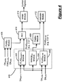
- FIG. 4 is a functional block diagram illustrating exemplary modules that execute the dosing agent monitoring control and the fuel level monitoring control.
- module refers to an application specific integrated circuit (ASIC), an electronic circuit, a processor (shared, dedicated, or group) and memory that execute one or more software or firmware programs, a combinational logic circuit, or other suitable components that provide the described functionality.
- ASIC application specific integrated circuit
- processor shared, dedicated, or group
- memory that execute one or more software or firmware programs, a combinational logic circuit, or other suitable components that provide the described functionality.
- the vehicle system 10 includes an engine system 12 , an exhaust after-treatment system 14 .
- the engine system 12 includes an engine 16 having a cylinder 18 , an intake manifold 20 and an exhaust manifold 22 . Air flows into the intake manifold and is mixed with fuel. The air and fuel mixture is combusted within the cylinder 18 to drive a piston (not shown).
- a single cylinder 18 is illustrated, it is appreciated that the engine 12 may include additional cylinders 18 .
- engines having 2, 3, 4, 5, 6, 8, 10, 12 and 16 cylinders are anticipated.
- the fuel is provided from a fuel source 26 and is injected into the air stream using an injector 28 .
- a fuel level sensor 30 is responsive to the amount of fuel within the fuel source 26 .
- the exhaust after-treatment system 14 treats the exhaust flowing therethrough to reduce emissions before being released to the atmosphere.
- the exhaust after-treatment system 14 includes a dosing system 32 , a diesel oxidation catalyst (DOC) 34 , an emissions sensor 36 and a catalyst 38 that is preferably provided as a selective catalytic (SCR) catalyst.
- the DOC 34 reacts with the exhaust to reduce emission levels of the exhaust.
- the emissions sensor 36 is responsive to an emissions (e.g., NOx) level of the exhaust. It is also anticipated that a diesel particulate filter (DPF) 40 may be located downstream from the catalyst 30 that filters diesel particulates to further reduce emissions.
- DPF diesel particulate filter
- the dosing system 32 includes a dosing agent injector 42 , a dosing agent storage tank 44 and a dosing agent supply sensor 46 .
- the dosing system 32 selectively injects a dosing agent (e.g., urea) into the exhaust stream to further reduce emissions. More specifically, the amount of the dosing agent injected is determined based on various parameters, for example, by using a model-based approach.
- the signal generated by the exhaust sensor provides a feedback parameter that can be used to monitor the accuracy of the calculated dosing agent amount and/or to check that the dosing agent properties are correct.
- the exhaust and dosing agent mixture reacts within the catalyst 38 to further reduce exhaust emissions.
- a control module 50 regulates operation of the vehicle system 10 based on the dosing agent monitoring control of the present invention. More specifically, the control module 50 determines a dosing agent level (DA LEVEL ) based on the signal generated by the dosing agent supply sensor 46 . The control module can calculate a vehicle range (RANGE DA ) based on the amount of dosing agent remaining. More specifically, RANGE DA indicates the remaining drivable distance before the entire dosing agent is consumed. RANGE DA can be displayed on a display (not shown) to alert the vehicle operator.
- DA LEVEL dosing agent level
- the control module can calculate a vehicle range (RANGE DA ) based on the amount of dosing agent remaining. More specifically, RANGE DA indicates the remaining drivable distance before the entire dosing agent is consumed. RANGE DA can be displayed on a display (not shown) to alert the vehicle operator.
- DA LEVEL is below a first predetermined or low dosing agent threshold value (DA LOW )
- the control module 50 sets a low dosing agent flag (FLAG DALOW ) (e.g., equal to 1 or TRUE) indicating that the dosing agent level is low and should be refilled.
- FLAG DALOW a low dosing agent flag
- the control module 50 activates an indicator 52 that alerts the vehicle operator that the dosing agent supply is low and should be refilled.
- the indicator 52 can be a visual and/or audible indication that alerts the vehicle operator to the low condition.
- DA LEVEL is below a second predetermined or empty dosing agent threshold value (DA EMPTY )
- the control module 50 sets an empty dosing agent flag (FLAG DAEMPTY ) (e.g., equal to 1 or TRUE). Further, the control module 50 activates the indicator 52 to indicate that the dosing agent source 44 is empty.
- FLAG DAEMPTY an empty dosing agent flag
- the control module 50 activates the indicator 52 to indicate that the dosing agent source 44 is empty.
- FLAG DAEMPTY and/or FLAG DALOW is/are cleared and the indicator 52 is also cleared.
- the dosing agent monitoring control selectively impedes vehicle operation when the dosing agent is empty. More specifically, if FLAG DAEMPTY is set and the vehicle is stopped at a convenient location (i.e., a location where additional dosing agent is likely to be available) the dosing agent monitoring control inhibits operation of the vehicle by setting a disable flag (FLAG DIS ) until the dosing agent is replenished. Operation of the vehicle can be impeded by either rendering the vehicle not drivable (e.g., preventing engine start or crank) or by limiting the drivability of the vehicle (e.g., a limp-home mode).
- FLAG DIS disable flag
- a convenient location flag (FLAG CL ) is set (e.g., equal to 1 or TRUE).
- a convenient location can include, but is not limited to, a fuel station, a maintenance workshop and/or an oil change workshop.
- the dosing agent monitoring control can monitor a fuel level before and after the vehicle is stopped. If the fuel level has increased, the dosing agent monitoring control determines that the vehicle was stopped to refuel and is therefore at a convenient location (i.e., fueling station) where additional dosing agent is available.
- the dosing agent monitoring control can monitor either an oil level or an oil parameter (e.g., an electrical property such as impedance) to determine whether an oil change has occurred. If so, the dosing agent monitoring control determines that the vehicle was stopped for an oil change and is therefore at a convenient location (i.e., oil change workshop) where additional dosing agent is available.
- an oil level or an oil parameter e.g., an electrical property such as impedance
- the dosing agent monitoring control can monitor vehicle maintenance flags in memory that are reset immediately after a maintenance event has occurred. In this manner, the dosing agent monitoring control can identify when the vehicle is in a maintenance workshop and can impede vehicle operation until the dosing agent is replenished.
- dosing agent monitoring control is described in further detail below using the fueling station scenario as an example, it is appreciated that the dosing agent monitoring control can monitor any of the above-described scenarios to determine whether the vehicle is located in a convenient location.
- control determines FLAG CL .
- An exemplary determination of FLAG CL is described in further detail below with regard to FIG. 3 .
- control monitors DA LEVEL .
- Control calculates and displays RANG DA in step 204 based on DA LEVEL .
- control determines whether DA LEVEL is less than DA LOW . If DA LEVEL is not less than DA LOW , control clears al dosing agent related flags in step 208 and control ends. If DA LEVEL is less than DA LOW , control determines whether DA LEVEL is less than DA EMPTY in step 210 . If DA LEVEL is not less than DA EMPTY , control sets FLAG DALOW in step 212 and control continues in step 214 . If DA LEVEL is less than DA EMPTY , control sets FLAG DAEMPTY in step 216 and control continues in step 218 .
- control determines whether FLAG CL is set. If FLAG CL is not set, control continues in step 214 . If FLAG CL is set, control sets FLAG DIS in step 220 . Control inhibits vehicle operation in step 222 and continues in step 214 .
- control displays the dosing agent status based on the dosing agent related flags and control ends. For example, “Dosing Agent Low”, “Dosing Agent Empty” or “Vehicle Disable Due To Empty Dosing Agent” messages can be displayed.
- step 300 control determines whether an engine start just occurred. If an engine start occurred, control continues in step 302 . If an engine start did not occur, control continues in step 304 .
- control determines FUEL LEVEL .
- control determines ⁇ FUEL LEVEL as the difference between FUEL LEVEL and the fuel level that was stored in memory immediately prior to the last engine shut-off event.
- control determines whether ⁇ FUEL LEVEL is greater than a threshold difference ( ⁇ THR ). If ⁇ FUEL LEVEL is greater than ⁇ THR , control determines that the vehicle was refueled during the most recent shut-down and continues in step 310 . If ⁇ FUEL LEVEL is not greater than ⁇ THR , control determines that the vehicle was not refueled during the most recent shut-down and continues in step 312 .
- step 304 control continuously monitors FUEL LEVEL .
- step 314 control determines whether FUEL LEVEL is increasing at a rate (e.g., dFL/dt) greater than a threshold rate (e.g., dFL/dt THR ). If dFL/dt is greater than dFL/dt THR , control determines that the vehicle is being refueled and continues in step 310 . If dFL/dt is not greater than dFL/dt THR , control determines that the vehicle is not being refueled and continues in step 312 . In step 310 , control sets FLAG CL . In step 312 , control stores the new or most recent FUEL LEVEL into memory and control ends.
- a rate e.g., dFL/dt
- a threshold rate e.g., dFL/dt THR
- the dosing agent monitoring control can monitor other scenarios including, but not limited to, maintenance and/or oil change to determine whether the vehicle is located in a convenient location.
- the dosing agent monitoring control can monitor vehicle maintenance flags stored in memory and determine that the vehicle is at a convenient location if one or more maintenance related flags are set or reset.
- the dosing agent control can monitor an oil level or an oil characteristic.
- the dosing agent monitoring control can determine that the vehicle is at a convenient location to refill the dosing agent.
- the exemplary modules include a FLAG DALOW module 400 , a FLAG EMPTY module 402 , a RANGE DA module 404 , a FLAG CL module 406 , a display module 408 , an AND module 410 , an indicator module 412 and an inhibit module 414 .
- the FLAG DALOW module 400 , the FLAG EMPTY module 402 and the RANGE DA module 404 can be individual modules or can be sub-modules within a larger module 416 .
- the FLAG DALOW module 400 selectively sets FLAG DALOW based on DA LEVEL and DA LOW .
- the FLAG DAEMPTY module 402 selectively sets FLAG DAEMPTY based on DA LEVEL and DA EMPTY .
- the RANGE DA module 404 calculates RANGE DA based on DA LEVEL .
- the FLAG CL module 406 selectively sets FLAG CL based on FUEL LEVEL , OIL LEVEL and/or OIL PAR . It is also anticipated that FLAG CL can be selectively set based on maintenance flags or any other factor that would indicate the vehicle is at a convenient location.
- the display module 408 graphically displays RANGE DA to alert the vehicle operator to the remaining distance the vehicle can travel before the dosing agent source is empty or below a desired level.
- the AND module 410 generates a signal based on FLAG DAEMPTY and FLAG CL . For example, if both FLAG DAEMPTY and FLAG CL are set (e.g., equal to 1) the AND module 410 outputs a signal indicating that the dosing agent is empty and the vehicle is located at a convenient location.
- the indicator module 412 generates an indication signal (e.g., audible and/or visual) based on FLAG DAEMPTY or FLAG DALOW to alert the vehicle operator to the status of the dosing agent source.
- the inhibit module 414 selectively disables or limits vehicle operation based on the output of the AND module 410 . More specifically, the inhibit module 414 generates control signals that regulate the vehicle in a limp-home mode or disable vehicle operation until the dosing agent source is replenished.
Abstract
Description
Claims (21)
Priority Applications (3)
| Application Number | Priority Date | Filing Date | Title |
|---|---|---|---|
| US11/639,369 US8024920B2 (en) | 2006-05-30 | 2006-12-14 | Method of monitoring a dosing agent supply for treating exhaust |
| DE102007024203A DE102007024203B4 (en) | 2006-05-30 | 2007-05-24 | Monitoring a dosing agent supply for treating exhaust gas |
| CN2007101081970A CN101082297B (en) | 2006-05-30 | 2007-05-30 | Method of monitoring a dosing agent supply for treating exhaust |
Applications Claiming Priority (2)
| Application Number | Priority Date | Filing Date | Title |
|---|---|---|---|
| US80931506P | 2006-05-30 | 2006-05-30 | |
| US11/639,369 US8024920B2 (en) | 2006-05-30 | 2006-12-14 | Method of monitoring a dosing agent supply for treating exhaust |
Publications (2)
| Publication Number | Publication Date |
|---|---|
| US20070277508A1 US20070277508A1 (en) | 2007-12-06 |
| US8024920B2 true US8024920B2 (en) | 2011-09-27 |
Family
ID=38788531
Family Applications (1)
| Application Number | Title | Priority Date | Filing Date |
|---|---|---|---|
| US11/639,369 Expired - Fee Related US8024920B2 (en) | 2006-05-30 | 2006-12-14 | Method of monitoring a dosing agent supply for treating exhaust |
Country Status (3)
| Country | Link |
|---|---|
| US (1) | US8024920B2 (en) |
| CN (1) | CN101082297B (en) |
| DE (1) | DE102007024203B4 (en) |
Cited By (1)
| Publication number | Priority date | Publication date | Assignee | Title |
|---|---|---|---|---|
| US20100089037A1 (en) * | 2008-10-15 | 2010-04-15 | Ford Global Technologies, Llc | Optimized discrete level sensing system for vehicle reductant reservoir |
Families Citing this family (11)
| Publication number | Priority date | Publication date | Assignee | Title |
|---|---|---|---|---|
| FR2929644B1 (en) * | 2008-04-08 | 2012-11-16 | Peugeot Citroen Automobiles Sa | METHOD FOR CONTROLLING THE CONSUMPTION OF REDUCING AGENT IN AN SCR SYSTEM |
| GB2467164A (en) * | 2009-01-27 | 2010-07-28 | Agco Sa | Exhaust treatment warning system |
| US8584707B2 (en) * | 2009-04-22 | 2013-11-19 | International Engine Intellectual Property Company, Llc | Dosing manifold assembly |
| US20110072888A1 (en) * | 2009-04-22 | 2011-03-31 | Eaton Corporation | Method for leak detection in dosing system |
| FR2955611B1 (en) * | 2010-01-27 | 2013-07-05 | Peugeot Citroen Automobiles Sa | MAINTENANCE MANAGEMENT METHOD FOR A VEHICLE |
| DE102010049988A1 (en) * | 2010-10-28 | 2012-05-03 | Gm Global Technology Operations Llc (N.D.Ges.D. Staates Delaware) | Shut-off device for drive of vehicle i.e. passenger car, has determination unit for determining road performance under estimation of driving scenario, where drive is switched-off when substance stock falls below stock threshold value |
| DE102010056399A1 (en) * | 2010-12-28 | 2012-06-28 | GM Global Technology Operations LLC | Motor vehicle with an exhaust aftertreatment system and method for operating the motor vehicle |
| DE102011104299A1 (en) * | 2011-06-16 | 2012-12-20 | GM Global Technology Operations LLC (n. d. Gesetzen des Staates Delaware) | Method for operating driver assistance system of motor vehicle, involves determining whether refilling of perdetermined quantity of reducing agent is possible based on determined current quantity of reducing agent provided in motor vehicle |
| US20160362536A1 (en) * | 2015-06-11 | 2016-12-15 | Dragan Simovic | Low viscosity mannich base curing agents |
| DE102015219858A1 (en) * | 2015-10-13 | 2017-04-13 | Kautex Textron Gmbh & Co. Kg | Operating fluid tank system for motor vehicles and method for filling a fuel tank of a working fluid tank system |
| FR3044041B1 (en) * | 2015-11-20 | 2017-12-01 | Peugeot Citroen Automobiles Sa | ALARM METHOD FOR ALARMING ENGINE LIQUID REFUELING IN A MOTOR VEHICLE |
Citations (7)
| Publication number | Priority date | Publication date | Assignee | Title |
|---|---|---|---|---|
| DE4425018C1 (en) | 1994-07-15 | 1995-06-29 | Daimler Benz Ag | Diesel motor exhaust gas cleaner system |
| US6502390B2 (en) * | 2000-08-09 | 2003-01-07 | Dr. Ing. H.C.F. Porsche Aktiengesellschaft | Method and system for feeding a reducing agent into a catalyst device |
| DE10161449A1 (en) | 2001-12-14 | 2003-06-26 | Fev Motorentech Gmbh | Operating internal combustion engine with filling lock involves inhibiting filling of fuel tank and/or engine starting if predefined minimum quantity in operating medium tank is reached |
| DE10357120A1 (en) | 2003-12-06 | 2005-07-07 | Daimlerchrysler Ag | Emission control system for a motor vehicle with a reducing agent reservoir and method of operation therefor |
| US20060179830A1 (en) * | 2003-02-07 | 2006-08-17 | Yoshiki Kamon | Control device for contruction machine |
| US20060184307A1 (en) * | 2005-02-17 | 2006-08-17 | Denso Corporation | Travel assist system |
| US20080110158A1 (en) * | 2005-08-24 | 2008-05-15 | Nissan Diesel Motor Co., Ltd. | Exhaust emission purifying apparatus for engine |
Family Cites Families (1)
| Publication number | Priority date | Publication date | Assignee | Title |
|---|---|---|---|---|
| DE4038054A1 (en) * | 1990-11-29 | 1992-06-04 | Man Technologie Gmbh | METHOD AND DEVICE FOR SELECTIVE CATALYTIC NO (DOWN ARROW) X (DOWN ARROW) REDUCTION IN OXYGEN-BASED EXHAUST GASES |
-
2006
- 2006-12-14 US US11/639,369 patent/US8024920B2/en not_active Expired - Fee Related
-
2007
- 2007-05-24 DE DE102007024203A patent/DE102007024203B4/en not_active Revoked
- 2007-05-30 CN CN2007101081970A patent/CN101082297B/en not_active Expired - Fee Related
Patent Citations (8)
| Publication number | Priority date | Publication date | Assignee | Title |
|---|---|---|---|---|
| DE4425018C1 (en) | 1994-07-15 | 1995-06-29 | Daimler Benz Ag | Diesel motor exhaust gas cleaner system |
| US6502390B2 (en) * | 2000-08-09 | 2003-01-07 | Dr. Ing. H.C.F. Porsche Aktiengesellschaft | Method and system for feeding a reducing agent into a catalyst device |
| DE10161449A1 (en) | 2001-12-14 | 2003-06-26 | Fev Motorentech Gmbh | Operating internal combustion engine with filling lock involves inhibiting filling of fuel tank and/or engine starting if predefined minimum quantity in operating medium tank is reached |
| US7207318B2 (en) * | 2001-12-14 | 2007-04-24 | Fev Motorentechnik Gmbh | Method for operation of a device for energy conversion using a main fuel and at least one auxiliary fuel |
| US20060179830A1 (en) * | 2003-02-07 | 2006-08-17 | Yoshiki Kamon | Control device for contruction machine |
| DE10357120A1 (en) | 2003-12-06 | 2005-07-07 | Daimlerchrysler Ag | Emission control system for a motor vehicle with a reducing agent reservoir and method of operation therefor |
| US20060184307A1 (en) * | 2005-02-17 | 2006-08-17 | Denso Corporation | Travel assist system |
| US20080110158A1 (en) * | 2005-08-24 | 2008-05-15 | Nissan Diesel Motor Co., Ltd. | Exhaust emission purifying apparatus for engine |
Cited By (1)
| Publication number | Priority date | Publication date | Assignee | Title |
|---|---|---|---|---|
| US20100089037A1 (en) * | 2008-10-15 | 2010-04-15 | Ford Global Technologies, Llc | Optimized discrete level sensing system for vehicle reductant reservoir |
Also Published As
| Publication number | Publication date |
|---|---|
| CN101082297B (en) | 2010-12-22 |
| US20070277508A1 (en) | 2007-12-06 |
| DE102007024203B4 (en) | 2009-12-31 |
| CN101082297A (en) | 2007-12-05 |
| DE102007024203A1 (en) | 2008-01-31 |
Similar Documents
| Publication | Publication Date | Title |
|---|---|---|
| US8024920B2 (en) | Method of monitoring a dosing agent supply for treating exhaust | |
| US7992377B2 (en) | Diesel exhaust control during limp-home mode | |
| US9133750B2 (en) | Method and system for verifying the operation of an SCR catalyst | |
| US7946109B2 (en) | Emissions conformance for an exhaust after-treatment system having a dosing agent supply | |
| US10494972B2 (en) | System and method for diesel exhaust fluid injector cleaning | |
| US6427439B1 (en) | Method and system for NOx reduction | |
| JP4326976B2 (en) | Engine exhaust purification system | |
| CN102022170B (en) | Intrusive SCR efficiency testing system and method for vehicle with low temperature exhaust gas | |
| CN102022169B (en) | Exhaust diagnostic systems and methods for resetting after operation with poor reductant quality | |
| US8408055B2 (en) | Method to detect and mitigate unsolicited exotherms in a diesel aftertreatment system | |
| CN102536403B (en) | Utilize ammoniacal sensor to determine the system and method for SCR allocating system performance | |
| US10100695B2 (en) | Exhaust fluid dosing control system and method | |
| GB2402088A (en) | Diesel aftertreatment systems | |
| US8407985B2 (en) | Method of monitoring hydrocarbon levels in a diesel particulate filter | |
| CN105308282A (en) | System and method for diagnosing the selective catalytic reduction system of a motor vehicle | |
| US20160103110A1 (en) | Engine nox model | |
| CN114183224A (en) | Method and system for exhaust aftertreatment system | |
| JP5098479B2 (en) | Exhaust gas purification device for internal combustion engine | |
| US20120272639A1 (en) | Reductant Quality Sensor | |
| JP5553630B2 (en) | Exhaust gas purification device for internal combustion engine | |
| US8940260B2 (en) | Supplemental ammonia storage and delivery system | |
| WO2015116145A1 (en) | On-board diagnostic monitoring of selective catalytic reduction catalysts | |
| JP2016169655A (en) | Remaining additive amount detection device | |
| KR102177356B1 (en) | Engine control apparatus and engine control method by urea quality | |
| EP2664759B1 (en) | Exhaust emission control apparatus and exhaust emission control method for internal combustion engine |
Legal Events
| Date | Code | Title | Description |
|---|---|---|---|
| AS | Assignment |
Owner name: GM GLOBAL TECHNOLOGY OPERATIONS, INC, MICHIGAN Free format text: ASSIGNMENT OF ASSIGNORS INTEREST;ASSIGNOR:HENDRICKSON, BRENT D.;REEL/FRAME:019015/0542 Effective date: 20070116 |
|
| AS | Assignment |
Owner name: UNITED STATES DEPARTMENT OF THE TREASURY, DISTRICT Free format text: SECURITY AGREEMENT;ASSIGNOR:GM GLOBAL TECHNOLOGY OPERATIONS, INC.;REEL/FRAME:022201/0363 Effective date: 20081231 Owner name: UNITED STATES DEPARTMENT OF THE TREASURY,DISTRICT Free format text: SECURITY AGREEMENT;ASSIGNOR:GM GLOBAL TECHNOLOGY OPERATIONS, INC.;REEL/FRAME:022201/0363 Effective date: 20081231 |
|
| AS | Assignment |
Owner name: CITICORP USA, INC. AS AGENT FOR BANK PRIORITY SECU Free format text: SECURITY AGREEMENT;ASSIGNOR:GM GLOBAL TECHNOLOGY OPERATIONS, INC.;REEL/FRAME:022553/0540 Effective date: 20090409 Owner name: CITICORP USA, INC. AS AGENT FOR HEDGE PRIORITY SEC Free format text: SECURITY AGREEMENT;ASSIGNOR:GM GLOBAL TECHNOLOGY OPERATIONS, INC.;REEL/FRAME:022553/0540 Effective date: 20090409 |
|
| AS | Assignment |
Owner name: GM GLOBAL TECHNOLOGY OPERATIONS, INC., MICHIGAN Free format text: RELEASE BY SECURED PARTY;ASSIGNOR:UNITED STATES DEPARTMENT OF THE TREASURY;REEL/FRAME:023124/0563 Effective date: 20090709 Owner name: GM GLOBAL TECHNOLOGY OPERATIONS, INC.,MICHIGAN Free format text: RELEASE BY SECURED PARTY;ASSIGNOR:UNITED STATES DEPARTMENT OF THE TREASURY;REEL/FRAME:023124/0563 Effective date: 20090709 |
|
| AS | Assignment |
Owner name: GM GLOBAL TECHNOLOGY OPERATIONS, INC., MICHIGAN Free format text: RELEASE BY SECURED PARTY;ASSIGNORS:CITICORP USA, INC. AS AGENT FOR BANK PRIORITY SECURED PARTIES;CITICORP USA, INC. AS AGENT FOR HEDGE PRIORITY SECURED PARTIES;REEL/FRAME:023155/0663 Effective date: 20090814 Owner name: GM GLOBAL TECHNOLOGY OPERATIONS, INC.,MICHIGAN Free format text: RELEASE BY SECURED PARTY;ASSIGNORS:CITICORP USA, INC. AS AGENT FOR BANK PRIORITY SECURED PARTIES;CITICORP USA, INC. AS AGENT FOR HEDGE PRIORITY SECURED PARTIES;REEL/FRAME:023155/0663 Effective date: 20090814 |
|
| AS | Assignment |
Owner name: UNITED STATES DEPARTMENT OF THE TREASURY, DISTRICT Free format text: SECURITY AGREEMENT;ASSIGNOR:GM GLOBAL TECHNOLOGY OPERATIONS, INC.;REEL/FRAME:023156/0264 Effective date: 20090710 Owner name: UNITED STATES DEPARTMENT OF THE TREASURY,DISTRICT Free format text: SECURITY AGREEMENT;ASSIGNOR:GM GLOBAL TECHNOLOGY OPERATIONS, INC.;REEL/FRAME:023156/0264 Effective date: 20090710 |
|
| AS | Assignment |
Owner name: UAW RETIREE MEDICAL BENEFITS TRUST, MICHIGAN Free format text: SECURITY AGREEMENT;ASSIGNOR:GM GLOBAL TECHNOLOGY OPERATIONS, INC.;REEL/FRAME:023162/0140 Effective date: 20090710 Owner name: UAW RETIREE MEDICAL BENEFITS TRUST,MICHIGAN Free format text: SECURITY AGREEMENT;ASSIGNOR:GM GLOBAL TECHNOLOGY OPERATIONS, INC.;REEL/FRAME:023162/0140 Effective date: 20090710 |
|
| FEPP | Fee payment procedure |
Free format text: PAYOR NUMBER ASSIGNED (ORIGINAL EVENT CODE: ASPN); ENTITY STATUS OF PATENT OWNER: LARGE ENTITY |
|
| AS | Assignment |
Owner name: GM GLOBAL TECHNOLOGY OPERATIONS, INC., MICHIGAN Free format text: RELEASE BY SECURED PARTY;ASSIGNOR:UNITED STATES DEPARTMENT OF THE TREASURY;REEL/FRAME:025245/0656 Effective date: 20100420 |
|
| AS | Assignment |
Owner name: GM GLOBAL TECHNOLOGY OPERATIONS, INC., MICHIGAN Free format text: RELEASE BY SECURED PARTY;ASSIGNOR:UAW RETIREE MEDICAL BENEFITS TRUST;REEL/FRAME:025314/0946 Effective date: 20101026 |
|
| AS | Assignment |
Owner name: WILMINGTON TRUST COMPANY, DELAWARE Free format text: SECURITY AGREEMENT;ASSIGNOR:GM GLOBAL TECHNOLOGY OPERATIONS, INC.;REEL/FRAME:025324/0057 Effective date: 20101027 |
|
| AS | Assignment |
Owner name: GM GLOBAL TECHNOLOGY OPERATIONS LLC, MICHIGAN Free format text: CHANGE OF NAME;ASSIGNOR:GM GLOBAL TECHNOLOGY OPERATIONS, INC.;REEL/FRAME:025781/0001 Effective date: 20101202 |
|
| STCF | Information on status: patent grant |
Free format text: PATENTED CASE |
|
| AS | Assignment |
Owner name: GM GLOBAL TECHNOLOGY OPERATIONS LLC, MICHIGAN Free format text: RELEASE BY SECURED PARTY;ASSIGNOR:WILMINGTON TRUST COMPANY;REEL/FRAME:034184/0001 Effective date: 20141017 |
|
| FPAY | Fee payment |
Year of fee payment: 4 |
|
| FEPP | Fee payment procedure |
Free format text: MAINTENANCE FEE REMINDER MAILED (ORIGINAL EVENT CODE: REM.); ENTITY STATUS OF PATENT OWNER: LARGE ENTITY |
|
| LAPS | Lapse for failure to pay maintenance fees |
Free format text: PATENT EXPIRED FOR FAILURE TO PAY MAINTENANCE FEES (ORIGINAL EVENT CODE: EXP.); ENTITY STATUS OF PATENT OWNER: LARGE ENTITY |
|
| STCH | Information on status: patent discontinuation |
Free format text: PATENT EXPIRED DUE TO NONPAYMENT OF MAINTENANCE FEES UNDER 37 CFR 1.362 |
|
| FP | Lapsed due to failure to pay maintenance fee |
Effective date: 20190927 |