US802489A - Speed-changing device. - Google Patents
Speed-changing device. Download PDFInfo
- Publication number
- US802489A US802489A US23484504A US1904234845A US802489A US 802489 A US802489 A US 802489A US 23484504 A US23484504 A US 23484504A US 1904234845 A US1904234845 A US 1904234845A US 802489 A US802489 A US 802489A
- Authority
- US
- United States
- Prior art keywords
- shaft
- gears
- series
- keys
- speed
- Prior art date
- Legal status (The legal status is an assumption and is not a legal conclusion. Google has not performed a legal analysis and makes no representation as to the accuracy of the status listed.)
- Expired - Lifetime
Links
Images

Classifications
-
- F—MECHANICAL ENGINEERING; LIGHTING; HEATING; WEAPONS; BLASTING
- F16—ENGINEERING ELEMENTS AND UNITS; GENERAL MEASURES FOR PRODUCING AND MAINTAINING EFFECTIVE FUNCTIONING OF MACHINES OR INSTALLATIONS; THERMAL INSULATION IN GENERAL
- F16H—GEARING
- F16H3/00—Toothed gearings for conveying rotary motion with variable gear ratio or for reversing rotary motion
- F16H3/02—Toothed gearings for conveying rotary motion with variable gear ratio or for reversing rotary motion without gears having orbital motion
- F16H3/08—Toothed gearings for conveying rotary motion with variable gear ratio or for reversing rotary motion without gears having orbital motion exclusively or essentially with continuously meshing gears, that can be disengaged from their shafts
- F16H3/083—Toothed gearings for conveying rotary motion with variable gear ratio or for reversing rotary motion without gears having orbital motion exclusively or essentially with continuously meshing gears, that can be disengaged from their shafts with radially acting and axially controlled clutching members, e.g. sliding keys
-
- Y—GENERAL TAGGING OF NEW TECHNOLOGICAL DEVELOPMENTS; GENERAL TAGGING OF CROSS-SECTIONAL TECHNOLOGIES SPANNING OVER SEVERAL SECTIONS OF THE IPC; TECHNICAL SUBJECTS COVERED BY FORMER USPC CROSS-REFERENCE ART COLLECTIONS [XRACs] AND DIGESTS
- Y10—TECHNICAL SUBJECTS COVERED BY FORMER USPC
- Y10T—TECHNICAL SUBJECTS COVERED BY FORMER US CLASSIFICATION
- Y10T74/00—Machine element or mechanism
- Y10T74/19—Gearing
- Y10T74/19219—Interchangeably locked
- Y10T74/19377—Slidable keys or clutches
- Y10T74/19414—Single clutch shaft
- Y10T74/19419—Progressive
- Y10T74/19442—Single key
- Y10T74/19451—Spur gears
- Y10T74/1946—Sliding clutch carrier
Definitions
- My invention relates to speed-changing devices of the class adapted to use on drillpresses, other machine-tools,or elsewhere; and the objects of my improvement are to provide means to either accelerate or retard the speed of a driven from a driving shaft by turning a hand-wheel in the same direction, to provide a plural number of wide changes of speed bases from which liner graduations of speed may be affected, to provide means to actuate the device in a fixed from an adjustable position, and to construct and assemble the various parts for especial adaptation to use on upright drill-presses.
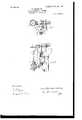
- FIG. 2 a side elevation, of my device applied to an upright drillpress, showing its connection with different parts thereof;
- Fig. 3 a vertical diametrical section unfolded with the shafts in the same plane;
- Fig. 4 a longitudinal diametrical section, and
- Fig. 5 a front elevation, of the shifting plates and connections;
- Fig. 6, a plan with parts in section on the line wwof .Fig. 4;
- Figs. 7 and 8 front and end elevations, respectively, of the rear shifting plate; and
- 11 represents the column of an upright drill-press, 12 the top yoke, 13 the main driving-shaft, 14 the spindle, 15 the spindle-sleeve provided with rack 16, 17 the sliding head, 18 the feed-gearing thereon for the spindle and engaging with the rack, and 19 the actuating-shaft therefor carried by the head, all constructed and arranged in the ordinary manner.
- Short shaft 23 is journaled in the casing, and bevel-gear 2 1, secured thereon, communicates, through pinion 25 and gear 26, with gear 27, secured on shaft 13.
- Hollow shaft 28, journaled in the casing, is formed with longitudinal slot 29 and provided with collar31.
- Gears 32 and 34 are each formed with a key-seat 35, adapted to register with slot 29 in shaft 28, and washers or rings 36 encircle said shaft between the gears thereon to close the ends of said key-seats.
- Similar collars 11 slidably encircle the depending portion of shaft 28 below the casing, and each are formed with an annular groove and with a lug 42, which extends through slot 29 and terminates Within the hollow of said shaft.
- Flat springs 39 are respectively secured on said lugs, and the taper keys 37 and 38 thereon are movable longitudinally within groove 29 by means of said collars and into engagement with the key-seats in respective gears 32 and 34:.
- Guide-box 43 depends from the casing and forms bearings for shaft 44, whereon mitergear is secured. and for the lower extremity of shaft 28.
- Shifting plates 15 and 46 are mounted to slide within the box and movably engage with the annular grooves in the respective collars by means of yokes 47 and 48 formed thereon.
- Rear plate is formed with a longitudinal slot 48 and with lugs 49 projecting therein from its opposite sides, the one a short distance above the other, and front plate 16, movable thereon, is formed with a longitudinal slot 51, having internal racks 52 on its respective sides.
- Segmental pinion 53 secured on shaft 44 and formed with segmental boss 54, is actuated by means of graduated hand-wheel 55, secured on shaft 50, which is journaled at one end in bearing 56, carried by the sliding head and movably splined through miter-pinion 57, which engages with gear-A0.
- Said pinion 53 is arranged to successively engage with racks 52 in its rotation in one direction and alternately shiftthe plate, together with its corresponding collar 41, in opposite directions,whereby taper key 38 is successively engaged with gears 3 1.
- plate 46 is immovable and boss 54.
- gears 32 forms the base of speed for shaft 28 during the movement of taper key 38 in an upward direction, and another gear 32 during the downward movement of said key through successive engagements with said gears 34:.
- gears 32 are graduated to liner differentiations by gears Si, and thereby communicated through shaft 19 and feed-gearing 18 to the feeding or longitudinal movement of spindle 14.
- aspeed-changing device the combination of a hollow shaft formed with a slot, a series of driven and a series of driving gears, idly mounted thereon and each formed with a key-seat adapted to register with the slot, taper keys within the shaft movable in the slot and means arranged to move the keys alternately into successive engagement with the gears of the respective series.
- a speed-changing device the combination of a hollow shaft formed with a slot, gears of different size mounted idly thereon and each having a key-seat adapted to register with the slot, a collar slidably movable on the shaft and formed with a lug extending through the slot within the hollow of the shaft, a spring secured at one end on the lug, and a taper key secured on the other end thereof and movable by means of the collar along the slot and into successive engagement with the successive gears.
- a speed-changing device the combination of a rotative shaft, collars slidable thereon, plates movably engaging wit-h the respective collars, the one formed with a double internal rack, the other with lugs projecting inwardly from the respective sides of a slot formed therein, a segmental pinion arranged to engage with the rack and formed with a boss adapted to alternately engage with the lugs whereby the plates are alternately reciprocated.
- a speed-changing device the combination of a hollow shaft formed with a slot, a double series of gears idly mounted thereon and containing key-seats to register with the slot, collars movable on the shaft, keys carried within the shaft by means of the collars and adapted to successively engage with the gears of the respective series, and means to alternately reciprocate the collars on the shaft.
- a speed-changing device the combination of a hollow shaft formed with a slot, collars movable thereon, keys carried within the hollow of the shaft by the collars, and a rackand-pinion mechanism arranged to move the collars independently.
- a speed-changing device the combination of a hollow shaft formed with a slot, a double series of gears mounted idly thereon and each gear formed with a key-seat to register with the slot, keys within the shaft movable into engagement with each gear of the respective series, a hand-wheel and rack-andpinion mechanism actuated thereby and arranged to move the keys, substantially as specified and for the purpose set forth.
Description
PATENTED OCT. 24, 1905.
H BAERBALOK. SPEED CHANGING 11mm. APPLICATION FILED NOV. 30, 1904.
2 SHEETS-SHEET 1 W/ M53515 3, 6 d MW @1 1 ,SZCQ/W I 4% N0. 5502,4429. PATENTED OCT. 24, 1905. H. BAERBALGK.
SPEED CHANGING DEVICE.
APPLICATION FILED NOV. 30, 1904.
2 SHEETSSHEET 2.
- MTNESSflE,
lrvvalvrotf.
HANS BAERBALOK, OF HAMILTON, OHIO, ASSlG-NOR TO HAMILTON MACHINE TOOL COMPANY, OF HAMILTON, OHIO, A CORPORA- TION OF OHIO.
SPIEIEID Cl'lANGlNG DEVICE.
Specification of Letters Patent.
Patented Oct. 24, 1905.
Application filed November 30, 1904. Serial No. 234,845.
To (all whom it may concern.-
Be it known that I, HANS BAERBALOK, a citizen of Germany, residing at Hamilton, Butler county, Ohio, have invented a new and useful Improvement in Speed-Ohanging Devices, of which the following is a specification.
My invention relates to speed-changing devices of the class adapted to use on drillpresses, other machine-tools,or elsewhere; and the objects of my improvement are to provide means to either accelerate or retard the speed of a driven from a driving shaft by turning a hand-wheel in the same direction, to provide a plural number of wide changes of speed bases from which liner graduations of speed may be affected, to provide means to actuate the device in a fixed from an adjustable position, and to construct and assemble the various parts for especial adaptation to use on upright drill-presses. These objects are attained in the following-described manner, as illustrated in the accompanying drawings, in which- Figure 1 is a plan, and Fig. 2 a side elevation, of my device applied to an upright drillpress, showing its connection with different parts thereof; Fig. 3, a vertical diametrical section unfolded with the shafts in the same plane; Fig. 4:, a longitudinal diametrical section, and Fig. 5 a front elevation, of the shifting plates and connections; Fig. 6, a plan with parts in section on the line wwof .Fig. 4; Figs. 7 and 8, front and end elevations, respectively, of the rear shifting plate; and Fig. 9, an isoinetrical view of the segmental pinion.
In the drawings, 11 represents the column of an upright drill-press, 12 the top yoke, 13 the main driving-shaft, 14 the spindle, 15 the spindle-sleeve provided with rack 16, 17 the sliding head, 18 the feed-gearing thereon for the spindle and engaging with the rack, and 19 the actuating-shaft therefor carried by the head, all constructed and arranged in the ordinary manner.
Oasing 21, secured on one side of the top yoke, contains a cone 22 of spur-gears splined on shaft 19. Short shaft 23 is journaled in the casing, and bevel-gear 2 1, secured thereon, communicates, through pinion 25 and gear 26, with gear 27, secured on shaft 13. Hollow shaft 28, journaled in the casing, is formed with longitudinal slot 29 and provided with collar31. A plural number of idle-spur-gears 32, of different sizes, mounted on said shaft above the collar, engage with corresponding gears 33, secured on shaft 23, and a series of idle spur-gears 34, mounted thereon below the collar, engage with corresponding gears of cone 22. Gears 32 and 34 are each formed with a key-seat 35, adapted to register with slot 29 in shaft 28, and washers or rings 36 encircle said shaft between the gears thereon to close the ends of said key-seats. Similar collars 11 slidably encircle the depending portion of shaft 28 below the casing, and each are formed with an annular groove and with a lug 42, which extends through slot 29 and terminates Within the hollow of said shaft. Flat springs 39 are respectively secured on said lugs, and the taper keys 37 and 38 thereon are movable longitudinally within groove 29 by means of said collars and into engagement with the key-seats in respective gears 32 and 34:.
Guide-box 43 depends from the casing and forms bearings for shaft 44, whereon mitergear is secured. and for the lower extremity of shaft 28. Shifting plates 15 and 46 are mounted to slide within the box and movably engage with the annular grooves in the respective collars by means of yokes 47 and 48 formed thereon. Rear plate is formed with a longitudinal slot 48 and with lugs 49 projecting therein from its opposite sides, the one a short distance above the other, and front plate 16, movable thereon, is formed with a longitudinal slot 51, having internal racks 52 on its respective sides.
Having fully described my improvement, what I claim as my invention, and desire to secure by Letters Patent of the United States, 1s-
1. The combination of a rotative shaft, two series of loose gears thereon, and a hand-actuated mechanism arranged to independently lock any gear of either series to the shaft.
2. The combination of a rotative shaft, two series of loose gears thereon, a rack-and-pinion mechanism, and keys alternately movable thereby and arranged to maintain either gear of one series in looking engagement with the shaft during the successive engagement with the shaft by means of the other key of the gears of the other series.
3. In aspeed-changing device, the combination of a hollow shaft formed with a slot, a series of driven and a series of driving gears, idly mounted thereon and each formed with a key-seat adapted to register with the slot, taper keys within the shaft movable in the slot and means arranged to move the keys alternately into successive engagement with the gears of the respective series.
4:. In a speed-changing device, the combination of a hollow shaft formed with a slot, gears of different size mounted idly thereon and each having a key-seat adapted to register with the slot, a collar slidably movable on the shaft and formed with a lug extending through the slot within the hollow of the shaft, a spring secured at one end on the lug, and a taper key secured on the other end thereof and movable by means of the collar along the slot and into successive engagement with the successive gears.
5. The combination of a rotative shaft, a series of driving and a series of driven gears idly mounted thereon, a hand-actuated mechanism,and keys alternately reciprocated thereby, one of said keys being arranged to lock and maintain in looking engagement with the shaft either of the driven gears during the separate engagement with the shaft by means of the other key of either of the driving-gears.
6. In a speed-changing device, the combination of a rotative shaft, collars slidable thereon, plates movably engaging wit-h the respective collars, the one formed with a double internal rack, the other with lugs projecting inwardly from the respective sides of a slot formed therein, a segmental pinion arranged to engage with the rack and formed with a boss adapted to alternately engage with the lugs whereby the plates are alternately reciprocated.
7. In a speed-changing device, the combination of a hollow shaft formed with a slot, a double series of gears idly mounted thereon and containing key-seats to register with the slot, collars movable on the shaft, keys carried within the shaft by means of the collars and adapted to successively engage with the gears of the respective series, and means to alternately reciprocate the collars on the shaft.
8. In a speed-changing device, the combination of a hollow shaft formed with a slot, collars movable thereon, keys carried within the hollow of the shaft by the collars, and a rackand-pinion mechanism arranged to move the collars independently.
9. In a speed-changing device, the combination of a hollow shaft formed with a slot, a double series of gears mounted idly thereon and each gear formed with a key-seat to register with the slot, keys within the shaft movable into engagement with each gear of the respective series, a hand-wheel and rack-andpinion mechanism actuated thereby and arranged to move the keys, substantially as specified and for the purpose set forth.
10. The combination of a rotative shaft, two series of idle gears thereon, hand-actuated mechanism and keys movable thereby and arranged to lock and maintain engaged with the shaft one gear of either'series during the independent and successive engagement thereby with the shaft of the gears of the other series.
11. The combination of a rotative shaft, two series of idle gears mounted thereon, keys adapted to lock either gear of the respective series with the shaft, and a hand-actuated device arranged to operate the keys alternately to successively lock and unlock the gears of the respective series.
12. The combination of a rotative shaft, a pair of idly-driven gears and a series of idle driving-gears thereon, respective keys adapted to lock either one of the driven and either one of the driving gears to the shaft, and a hand-operated device arranged to control the keys in maintaining one driven gear in locked position on the shaft during the successive and separate engagement of the driving-gears with the shaft in one direction through the series, and in maintaining the other driven gear in locked position during the successive and separate locking of the drivinggears through the series in the opposite direction.
13. The combination of a hollow rotative shaft, a pair of idle driven gears of different size, and also a series of idle driving-gears thereon, said driving-gears being graduated in size between the size of the driven gears, respective keys Within the shaft to separately lock either of the driven and either of the driving gears thereto, and a rack-and-pinion mechanism arranged to shift the keys to maintain the respective driven gears in locked engagem cut with the shaft during the successive engagement thereby with the shaft of the driving-gears in opposite directions through the series.
14:. The combination of a hollow shaft journaled in bearings, a pair of different-sized idle driven gears thereon, a series of idle drivinggears on the shaft, and graduated in size between the size of the driven gears, keys Within the shaft adapted to lock either of the respective driving or driven gears thereto, a graduated hand-wheel, and rack-and-pinion mechanism actuated thereby and controlling the keys whereby one key is caused to suecessively lock and unlock the driving-gears to the shaft during the engagement of the other key with either of the driven gears.
15. The combination of a shaft journaled in fixed bearings, a series of idle wheels thereon, a rack-and-pinion mechanism a key actuated thereby and arranged to lock either of the Wheels to the shaft, and a hand-wheel arranged to actuate said mechanism and ad justabl y supported in relation thereto.
16. The combination of a shaft, two pairs of intermeshing driven gears of different sizes, one gear of each pair being idle on the shaft, a plurality of pairs of intermeshing drivinggears graduated in size, one gear of each pair thereof being idle on said shaft, means for maintaining either of the driving and either of the driven gears in simultaneous engagement With the shaft, and a hand-wheel for controlling said means.
17. The combination of a hollow shaft, two groups of idle gears thereon, keys within the shaft movable plates connected to the keys, a hand-Wheel and rack-and-pinion mechanism actuated thereby to alternately move the plates with the keys into locking engagement with either of the gears of the respective groups.
HANS BAERBALCK.
Vitnesses:
ARTHUR LETI-IERBY, R. S. CARR.
Priority Applications (1)
| Application Number | Priority Date | Filing Date | Title |
|---|---|---|---|
| US23484504A US802489A (en) | 1904-11-30 | 1904-11-30 | Speed-changing device. |
Applications Claiming Priority (1)
| Application Number | Priority Date | Filing Date | Title |
|---|---|---|---|
| US23484504A US802489A (en) | 1904-11-30 | 1904-11-30 | Speed-changing device. |
Publications (1)
| Publication Number | Publication Date |
|---|---|
| US802489A true US802489A (en) | 1905-10-24 |
Family
ID=2870972
Family Applications (1)
| Application Number | Title | Priority Date | Filing Date |
|---|---|---|---|
| US23484504A Expired - Lifetime US802489A (en) | 1904-11-30 | 1904-11-30 | Speed-changing device. |
Country Status (1)
| Country | Link |
|---|---|
| US (1) | US802489A (en) |
Cited By (3)
| Publication number | Priority date | Publication date | Assignee | Title |
|---|---|---|---|---|
| US2416154A (en) * | 1943-06-23 | 1947-02-18 | Wright Aeronautical Corp | Transmission |
| US4283969A (en) * | 1977-06-27 | 1981-08-18 | Lapeyre Fernand S | Bicycle transmission |
| US5400671A (en) * | 1990-08-22 | 1995-03-28 | Dana Corporation | Side shifting mechanism for transaxle |
-
1904
- 1904-11-30 US US23484504A patent/US802489A/en not_active Expired - Lifetime
Cited By (3)
| Publication number | Priority date | Publication date | Assignee | Title |
|---|---|---|---|---|
| US2416154A (en) * | 1943-06-23 | 1947-02-18 | Wright Aeronautical Corp | Transmission |
| US4283969A (en) * | 1977-06-27 | 1981-08-18 | Lapeyre Fernand S | Bicycle transmission |
| US5400671A (en) * | 1990-08-22 | 1995-03-28 | Dana Corporation | Side shifting mechanism for transaxle |
Similar Documents
| Publication | Publication Date | Title |
|---|---|---|
| US802489A (en) | Speed-changing device. | |
| US676197A (en) | Radial drill. | |
| US767866A (en) | Variable-speed and reversing gear. | |
| US452991A (en) | Mechanical movement | |
| US1231880A (en) | Gearing. | |
| US994899A (en) | Gearing. | |
| US730146A (en) | Variable-speed mechanism. | |
| US684432A (en) | Engine-lathe. | |
| US724312A (en) | Variable-speed gear. | |
| US156758A (en) | Improvement in feed mechanisms for lathes | |
| US643191A (en) | Speed-changing gear for engine-lathes. | |
| US1123881A (en) | Multiple-use machine of boring-mill type. | |
| US712058A (en) | Driving mechanism. | |
| US917015A (en) | Gearing for machine-tools. | |
| US670910A (en) | Feeding device. | |
| US695665A (en) | Feed mechanism for machine-tools. | |
| US1344236A (en) | Machine-tool | |
| US879216A (en) | Variable-speed mechanism. | |
| US804999A (en) | Variable-speed gearing. | |
| US683003A (en) | Variable-speed mechanism. | |
| US876083A (en) | Transmission-gearing. | |
| USRE13560E (en) | Gearing | |
| US686116A (en) | Drill. | |
| US1340585A (en) | Spindle-driving mechanism for machine-tools | |
| US458423A (en) | Lathe-head |