US8020189B2 - Fast adaptive channel converting method and apparatus, and computer readable recording medium for executing the fast adaptive channel converting method - Google Patents
Fast adaptive channel converting method and apparatus, and computer readable recording medium for executing the fast adaptive channel converting method Download PDFInfo
- Publication number
- US8020189B2 US8020189B2 US12/271,244 US27124408A US8020189B2 US 8020189 B2 US8020189 B2 US 8020189B2 US 27124408 A US27124408 A US 27124408A US 8020189 B2 US8020189 B2 US 8020189B2
- Authority
- US
- United States
- Prior art keywords
- channel
- signal
- adjacent
- fast adaptive
- changed
- Prior art date
- Legal status (The legal status is an assumption and is not a legal conclusion. Google has not performed a legal analysis and makes no representation as to the accuracy of the status listed.)
- Active, expires
Links
Images


Classifications
-
- H—ELECTRICITY
- H04—ELECTRIC COMMUNICATION TECHNIQUE
- H04N—PICTORIAL COMMUNICATION, e.g. TELEVISION
- H04N5/00—Details of television systems
- H04N5/44—Receiver circuitry for the reception of television signals according to analogue transmission standards
- H04N5/50—Tuning indicators; Automatic tuning control
-
- H—ELECTRICITY
- H04—ELECTRIC COMMUNICATION TECHNIQUE
- H04N—PICTORIAL COMMUNICATION, e.g. TELEVISION
- H04N21/00—Selective content distribution, e.g. interactive television or video on demand [VOD]
- H04N21/40—Client devices specifically adapted for the reception of or interaction with content, e.g. set-top-box [STB]; Operations thereof
- H04N21/43—Processing of content or additional data, e.g. demultiplexing additional data from a digital video stream; Elementary client operations, e.g. monitoring of home network or synchronising decoder's clock; Client middleware
- H04N21/443—OS processes, e.g. booting an STB, implementing a Java virtual machine in an STB or power management in an STB
-
- H—ELECTRICITY
- H04—ELECTRIC COMMUNICATION TECHNIQUE
- H04N—PICTORIAL COMMUNICATION, e.g. TELEVISION
- H04N21/00—Selective content distribution, e.g. interactive television or video on demand [VOD]
- H04N21/40—Client devices specifically adapted for the reception of or interaction with content, e.g. set-top-box [STB]; Operations thereof
- H04N21/41—Structure of client; Structure of client peripherals
- H04N21/426—Internal components of the client ; Characteristics thereof
- H04N21/42607—Internal components of the client ; Characteristics thereof for processing the incoming bitstream
- H04N21/4263—Internal components of the client ; Characteristics thereof for processing the incoming bitstream involving specific tuning arrangements, e.g. two tuners
-
- H—ELECTRICITY
- H04—ELECTRIC COMMUNICATION TECHNIQUE
- H04N—PICTORIAL COMMUNICATION, e.g. TELEVISION
- H04N21/00—Selective content distribution, e.g. interactive television or video on demand [VOD]
- H04N21/40—Client devices specifically adapted for the reception of or interaction with content, e.g. set-top-box [STB]; Operations thereof
- H04N21/43—Processing of content or additional data, e.g. demultiplexing additional data from a digital video stream; Elementary client operations, e.g. monitoring of home network or synchronising decoder's clock; Client middleware
- H04N21/438—Interfacing the downstream path of the transmission network originating from a server, e.g. retrieving encoded video stream packets from an IP network
- H04N21/4383—Accessing a communication channel
- H04N21/4384—Accessing a communication channel involving operations to reduce the access time, e.g. fast-tuning for reducing channel switching latency
-
- H—ELECTRICITY
- H04—ELECTRIC COMMUNICATION TECHNIQUE
- H04N—PICTORIAL COMMUNICATION, e.g. TELEVISION
- H04N21/00—Selective content distribution, e.g. interactive television or video on demand [VOD]
- H04N21/40—Client devices specifically adapted for the reception of or interaction with content, e.g. set-top-box [STB]; Operations thereof
- H04N21/43—Processing of content or additional data, e.g. demultiplexing additional data from a digital video stream; Elementary client operations, e.g. monitoring of home network or synchronising decoder's clock; Client middleware
- H04N21/439—Processing of audio elementary streams
- H04N21/4392—Processing of audio elementary streams involving audio buffer management
Definitions
- aspects of the present invention relate to changing a broadcast channel, and more particularly, to a fast adaptive channel changing method and apparatus of a digital broadcast channel.
- a digital broadcast reproducing apparatus such as a digital television (DTV) or a cable set-top box
- the digital broadcast reproducing apparatus detects channel mapping information, such as corresponding channel frequency information, by interpreting a channel change request from the user.
- the digital broadcast reproducing apparatus tunes a broadcast signal using a tuner by referring to the detected channel mapping information, and reproduces the tuned broadcast signal via demodulation and decoding.
- a halt time hereinafter, referred to as a screen blank time
- the user may be bored while waiting, or may purchase an analog TV instead of a DTV.
- aspects of the present invention provide a fast adaptive channel changing apparatus and method, which can prevent a screen blank time by using an unused resource of a digital broadcast reproducing apparatus, and a computer readable recording medium having recorded thereon a program for executing the fast adaptive channel converting method.
- a fast adaptive channel changing apparatus includes a signal processing unit to signal process at least two channel signals; a channel list managing unit to generate a channel list including channel information related to the at least two channel signals; and a main control unit to control the signal processing unit to pre-signal process an adjacent channel of a reference channel based on the channel list.
- a digital broadcast reproducing apparatus which includes the fast adaptive channel changing apparatus.
- a fast adaptive channel changing method includes generating adjacent channel data by pre-signal processing an adjacent channel signal of a reference channel; receiving a channel change request from a user; searching for channel data corresponding to a changed channel in the adjacent channel data; and reproducing the searched changed channel data.
- a computer readable recording medium having recorded thereon a program to execute a fast adaptive channel changing method, the method including generating adjacent channel data by pre-signal processing an adjacent channel signal of a reference channel; receiving a channel change request from a user; searching for channel data corresponding to the changed channel in the adjacent channel data; and reproducing the searched changed channel data.
- FIG. 1 is a block diagram illustrating a physical structure of a fast adaptive channel changing apparatus according to an embodiment of the present invention
- FIG. 2 is a flowchart illustrating a fast adaptive channel changing process according to an embodiment of the present invention
- FIG. 3 is a flowchart describing in detail processing of an adjacent channel signal (operation 23 ) of FIG. 2 ;
- FIG. 4 is a flowchart illustrating a fast adaptive channel changing process according to another embodiment of the present invention.
- FIG. 5A is a diagram illustrating an example of a channel list according to an embodiment of the present invention.
- FIG. 5B is a conceptual diagram for describing a process of generating a preferred channel list according to an embodiment of the present invention.
- FIG. 5C is a diagram illustrating an example of a preferred channel list according to an embodiment of the present invention.
- FIG. 1 shows a fast adaptive channel changing apparatus 100 according to an embodiment of the present invention.
- the fast adaptive channel changing apparatus 100 may be part of a digital television (DTV), a set-top box, or other digital broadcasting reproducing apparatus, or as an independent apparatus.
- DTV digital television
- set-top box or other digital broadcasting reproducing apparatus, or as an independent apparatus.
- the fast adaptive channel changing apparatus 100 includes a tuning unit 1 , a demodulation unit 2 , a decoding unit 3 , a buffering unit 4 , a main control unit 5 , a channel list managing unit 6 , an image display control unit 8 , an image display unit 8 , a remote control signal receiving unit 9 , and a storage unit 10 .
- the fast adaptive channel changing apparatus 100 may include additional and/or different units. Similarly, the functionality of two or more of the above units may be integrated into a single component.
- the tuning unit 1 , the demodulation unit 2 , the decoding unit 3 , and the buffering unit 4 respectively include N tuners 11 through 1 N, N demodulators 21 through 2 N, N A/V decoders 31 through 3 N, and N buffers 41 through 4 N.
- the number of the tuners 11 through 1 N is 2 through 4, but may be 5 or more in other aspects of the present invention.
- the tuning unit 1 tunes a signal of a certain channel by filtering a digital broadcasting signal received by the DTV or the like.
- the demodulation unit 2 modulates a channel signal tuned by the tuning unit 1 .
- the decoding unit 3 decodes a channel signal demodulated by the demodulation unit 2 .
- the buffering unit 4 temporarily stores the demodulated channel signal or the decoded channel data.
- a signal processing unit refers to the tuning unit 1 , the demodulation unit 2 , the decoding unit 3 , and the buffering unit 4 .
- the channel list managing unit 6 generates a channel list including channel information about all channel signals received by the DTV or the like.
- the channel list managing unit 6 may also generate a preferred channel list including channel information about channels having high audience frequencies.
- the main control unit 5 refers to the channel list or the preferred channel list, and controls the signal processing unit to pre-signal process adjacent channels of a channel that is currently being reproduced by the DTV (hereinafter, referred to as a reference channel).
- the main control unit 5 may generate a mapping table.
- the mapping table maps correspondence between pre-signal processed channel data and corresponding channel information.
- the main control unit 5 detects channel data corresponding to a changed channel from the buffering unit 4 by referring to the mapping table, and immediately displays or reproduces the channel data on the image display unit 8 .
- the storage unit 10 stores the demodulated channel signal, the channel data, the channel list, and the preferred channel list.
- the storage unit 10 stores data of a program that was being reproduced when the DTV is turned off. The channel list should be reproduced first so as to use the fast adaptive channel changing apparatus and method according to aspects of the present invention.
- the channel list managing unit 6 generates a channel list including channel information about all channels received through the DTV.
- FIG. 5A shows an example of the channel list according to an embodiment of the present invention.
- the channel list includes information used for tuning, demodulating, and decoding a channel signal, such as a channel number, a channel name, a center frequency, a QAM mode (64 or 256), and a program number.
- the channel list may be provided to a user (or the DTV) after being generated by a broadcast program provider, such as a content provider, a wired broadcasting station, or an airwave broadcasting station.
- signal processing refers to tuning, demodulating, and decoding a channel signal after receiving the channel signal. In some cases, “signal processing” may refer to tuning, demodulating, decoding, and storing a channel signal. “Channel data” is a term used to distinguish from a channel signal. “Channel data” refers to a signal processed channel signal generated by signal processing a channel signal.
- FIG. 2 is a flowchart of a fast adaptive channel changing process according to an embodiment of the present invention.
- channel information of a broadcast program that was being viewed by a user and program data that was being buffered or stored are stored in the storage unit 10 even when the DTV is turned off.
- the user turns on the DTV in operation 21 .
- the main control unit 5 signal processes program data that has been stored when the DTV was turned off, displays the program data on the image display unit 8 , and then stands by for the user to input a channel change signal in operation 22 .
- the main control unit 5 signal processes adjacent channels of a reference channel, i.e., a current channel displayed on the image display unit 8 in operation 23 . Operation 23 will be described in detail later with reference to FIG. 3 .
- the user converts (or changes) a currently viewed channel to another channel using a remote controller or the like.
- a channel change signal is received through the remote control signal receiving unit 9 , and the main control unit 5 establishes the changed channel as a new reference channel by analyzing the channel change signal, and signal processes adjacent channels of the new reference channel in operation 23 .
- the main control unit 5 When a channel is changed, the main control unit 5 first examines the mapping table stored in the storage unit 10 in operation 25 , and determines whether the converted channel received in operation 24 is included in the mapping table in operation 26 .
- the mapping table prepared in operation 37 of FIG. 3 includes information about channel data that is signal processed and stored in the buffering unit 4 or the storage unit 10 .
- the changed channel is not included in the mapping table in operation 26 , then signal processing and storing have not been performed yet for the newly changed channel. Accordingly, data of the previous (or reference) channel that was being reproduced before changing the channel is continuously reproduced in operation 27 in order to prevent a screen blank time. At the same time, a signal of the newly converted channel is started to be signal processed in operation 28 . After a predetermined time, such as 1.8 seconds after the channel is changed, a part of the signal of the changed channel is done being signal processed and prepared to be displayed on the image display unit 8 . The channel data that is signal processed in operation 28 is displayed on the image display unit 8 in operation 30 subsequently to image data of the reference channel displayed in operation 27 .
- the changed channel is included in the mapping table in operation 26 , information about channel data corresponding to the changed channel is detected from the mapping table.
- Channel data is read from the buffering unit 4 by referring to the detected information, and then displayed on the image display unit 8 in operation 29 .
- a signal of a newly converted (changed) channel is started to be signal processed in operation 28 .
- the predetermined time such as 1.8 seconds after the channel is converted, a part of the signal of the newly changed channel is done being signal processed and prepared to be displayed on the image display unit 8 .
- the channel data signal processed in operation 28 is synchronized with the channel data displayed in operation 29 , and displayed on the image display unit 8 without any screen blank time in operation 30 .
- FIG. 3 is a flowchart describing in detail processing of the adjacent channel signal (operation 23 ) of FIG. 2 .
- Operations 31 through 37 are performed in a background processing technique, and repeatedly performed for each adjacent channel.
- the main control unit 5 obtains channel information about adjacent channels of the channel that is currently being reproduced by referring to the channel list of FIG. 5A in operation 31 .
- channel information about a predetermined number (for example, 2) of adjacent channels (for example, MBC and EBS) that are below the current channel is obtained.
- channel information about two adjacent channels (for example, KBS 1 and SBS) above the current channel, or channel information about an above adjacent channel (for example, KBS 1 ) and a below adjacent channel (for example, MBC) may be obtained.
- the main control unit 5 assigns an idle tuner to tune an adjacent channel signal. For example, when the tuner 11 is assigned for a channel that is being reproduced on the image display unit 8 , remaining tuners 12 through 1 N are each assigned for adjacent channels.
- a tuner establishes a tuning frequency by referring to a center frequency obtained in operation 31 , and filters a transport stream (TS) of the corresponding channel in operation 32 .
- TS transport stream
- the main control unit 5 assigns an idle demodulator, and the assigned idle demodulator demodulates the adjacent channel signal tuned in operation 32 .
- the demodulated adjacent channel signals are stored in a buffer in operation 33 .
- the demodulated adjacent channel signals are decoded by an A/V decoder, and then again stored in the buffer in operation 34 .
- a tuned channel signal includes a plurality of program signals, only one program signal is decoded and stored. Accordingly, channel data of an adjacent channel is generated.
- each tuned channel signal includes a plurality of programs. If the tuned channel signal includes a plurality of programs, the program signals excluding one program signal that was decoded and stored are stored in the buffering unit 4 or the storage unit 10 in operation 36 .
- the main control unit 5 generates a mapping table by mapping the signal decoded in operation 34 and corresponding adjacent channel information, by referring to the channel list, and stores the mapping table in the storage unit 10 in operation 37 .
- a buffer to store a signal demodulated in operation 33 and a buffer to store a signal decoded in operation 35 may be physically one buffer, or separate individual buffers.
- the number of adjacent channels signal processed in operation 32 through 34 is determined based on resources of the DTV (a tuner, a demodulator, an A/V decoder, and a buffer), the amount of data that are signal processed for each channel, etc.
- the amount of data of each adjacent channel that is signal processed in operations 32 through 37 may be determined within a range between 1 through 5 seconds (for example 1.8 seconds) based on an average channel changing time of the user, the number of idle resources, a screen blank time, or the like.
- FIG. 4 is a flowchart of a fast adaptive channel changing process according to another embodiment of the present invention.
- the user changes a channel to an adjacent channel included in a mapping table.
- the user changes the channel using a channel up key, a channel down key, or a number key of a remote controller.
- a signal of the changed channel is assumed to be pre signal processed in operation 43 .
- an operation of the method of FIG. 4 is equal to an operation of the process of FIG. 2 , the detailed description thereof will be omitted or summarized.
- the main control unit 5 displays channel data stored in the storage unit 10 on the image display unit 8 , while standing by for a channel change signal to be inputted by the user in operations 41 and 42 .
- the main control unit 5 signal processes channels adjacent to the channel that is currently being reproduced in operation 43 .
- the channel change signal is received via the remote control signal receiver 9 in operation 44 .
- the main control unit 5 establishes the changed channel as a new reference channel, and signal processes adjacent channels of the new reference channel in operation 43 .
- image data of the changed channel stored in the buffering unit 4 that was pre-signal processed in operation 43 is read and displayed on the image display unit 8 in operation 45 .
- a signal of the newly changed channel is started to be signal processed in operation 46 .
- a predetermined time after the channel is changed a part of the signal of the changed channel is done being signal processed and is prepared to be displayed on the image display unit 8 .
- the changed channel data that is signal processed in operation 46 is synchronized with the image data displayed in operation 45 , and displayed on the image display unit 8 in operation 47 without any screen blank time.
- the fast adaptive channel converting process may be applied only to preferred channels or part of channels.
- the channel conversion is performed using the channel list of FIG. 5A for all channels received by the DTV.
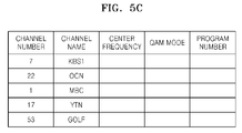
- the fast adaptive channel converting method may be performed based on a preferred channel list illustrated in FIG. 5C .
- a preferred channel list may be pre-generated by the channel list managing unit 6 and stored in the storage unit 10 . A process of generating a preferred channel list will now be described with reference to FIGS. 5B and 5C .
- the channel list managing unit 6 arranges channels preferred by the user by normally monitoring channel change signals received from the remote control signal receiver 9 .
- a predetermined number for example, 5, 20, 50, etc., of channels are selected in proportion to audience frequency, and then a channel list of the selected channels may be generated.
- FIG. 5B is a conceptual diagram for describing a process of generating a preferred channel list according to an embodiment of the present invention.
- FIG. 5 B(a) shows all channels received by the DTV. From these channels, a predetermined number, for example 5, of channels having high audience frequency is selected, for example, KBS 1 , MBC, GOLF, OCN, and YTN. The selected channels are arranged in such a way that a channel having the highest audience frequency is on the top as shown in FIG. 5 B(b). For example, if the audience frequency of OCN is the second, unlike FIG. 5 B(a), OCN is located above MBC in FIG. 5 B(b).
- FIG. 5C shows an example of the preferred channel list generated by using the method of FIG. 5B . According to an embodiment of the present invention, the preferred channel list may be displayed on the image display unit 8 so as to help the user with the channel changing.
- the fast adaptive channel changing apparatus and method prevent a screen blank time that may occur while changing a channel in a digital broadcast receiving apparatus, and thus boredom or inconvenience of a user can be removed.
- a channel search time can be remarkably reduced, and the user can easily watch a program of a preferred channel.
- aspects of the present invention can also be embodied as computer readable codes on a computer readable recording medium.
- the computer readable recording medium is any data storage device that can store data which can be thereafter read by a computer system. Examples of the computer readable recording medium include read-only memory (ROM), random-access memory (RAM), CDs, DVDs, magnetic tapes, floppy disks, and optical data storage devices.
- ROM read-only memory
- RAM random-access memory
- CDs compact discs
- DVDs magnetic tapes
- floppy disks compact discs
- optical data storage devices embodied as carrier waves (such as data transmission through the Internet).
- the computer readable recording medium can also be distributed over network coupled computer systems so that the computer readable code is stored and executed in a distributed fashion.
Landscapes
- Engineering & Computer Science (AREA)
- Multimedia (AREA)
- Signal Processing (AREA)
- Software Systems (AREA)
- Two-Way Televisions, Distribution Of Moving Picture Or The Like (AREA)
- Circuits Of Receivers In General (AREA)
Abstract
Description
Claims (30)
Applications Claiming Priority (3)
| Application Number | Priority Date | Filing Date | Title |
|---|---|---|---|
| KR10-2008-0015911 | 2008-02-21 | ||
| KR2008-15911 | 2008-02-21 | ||
| KR1020080015911A KR20090090600A (en) | 2008-02-21 | 2008-02-21 | Method and apparatus for fast channel switching, and computer program storage medium for performing the method |
Publications (2)
| Publication Number | Publication Date |
|---|---|
| US20090217339A1 US20090217339A1 (en) | 2009-08-27 |
| US8020189B2 true US8020189B2 (en) | 2011-09-13 |
Family
ID=40999687
Family Applications (1)
| Application Number | Title | Priority Date | Filing Date |
|---|---|---|---|
| US12/271,244 Active 2029-10-03 US8020189B2 (en) | 2008-02-21 | 2008-11-14 | Fast adaptive channel converting method and apparatus, and computer readable recording medium for executing the fast adaptive channel converting method |
Country Status (2)
| Country | Link |
|---|---|
| US (1) | US8020189B2 (en) |
| KR (1) | KR20090090600A (en) |
Cited By (1)
| Publication number | Priority date | Publication date | Assignee | Title |
|---|---|---|---|---|
| US11606621B2 (en) | 2017-06-15 | 2023-03-14 | At&T Intellectual Property I, L.P. | Method of providing personalized channel change lists |
Families Citing this family (14)
| Publication number | Priority date | Publication date | Assignee | Title |
|---|---|---|---|---|
| US20120287645A1 (en) * | 2009-12-08 | 2012-11-15 | Junhwan Ju | Display apparatus |
| WO2015013645A1 (en) | 2013-07-25 | 2015-01-29 | Convida Wireless, Llc | End-to-end m2m service layer sessions |
| US20150089073A1 (en) | 2013-09-25 | 2015-03-26 | Ericsson Television Inc | System and method for effectuating fast channel change in an adpative streaming environment |
| US9444856B2 (en) * | 2013-09-25 | 2016-09-13 | Ericsson Ab | System and method for managing adjacent channels in an adaptive streaming environment |
| JP6935426B2 (en) | 2016-05-11 | 2021-09-15 | コンヴィーダ ワイヤレス, エルエルシー | New wireless downlink control channel |
| EP3456058B1 (en) | 2016-05-13 | 2025-01-08 | InterDigital Madison Patent Holdings, SAS | Bit depth remapping based on viewing parameters |
| WO2018005835A1 (en) * | 2016-07-01 | 2018-01-04 | Vid Scale, Inc. | Systems and methods for fast channel change |
| US11503314B2 (en) | 2016-07-08 | 2022-11-15 | Interdigital Madison Patent Holdings, Sas | Systems and methods for region-of-interest tone remapping |
| EP3497812A1 (en) | 2016-08-11 | 2019-06-19 | Convida Wireless, LLC | Beamforming sweeping and training in a flexible frame structure for new radio |
| US11159847B2 (en) * | 2016-09-22 | 2021-10-26 | DISH Technologies L.L.C. | Apparatus, systems and methods for reducing time required for a media content event channel change |
| WO2018097947A2 (en) | 2016-11-03 | 2018-05-31 | Convida Wireless, Llc | Reference signals and control channels in nr |
| US11765406B2 (en) | 2017-02-17 | 2023-09-19 | Interdigital Madison Patent Holdings, Sas | Systems and methods for selective object-of-interest zooming in streaming video |
| KR102628139B1 (en) | 2017-03-07 | 2024-01-22 | 인터디지털 매디슨 페턴트 홀딩스 에스에이에스 | Customized video streaming for multi-device presentations |
| WO2020068251A1 (en) | 2018-09-27 | 2020-04-02 | Convida Wireless, Llc | Sub-band operations in unlicensed spectrums of new radio |
Citations (2)
| Publication number | Priority date | Publication date | Assignee | Title |
|---|---|---|---|---|
| US20080092203A1 (en) * | 2006-10-13 | 2008-04-17 | Nokia Corporation | Approach for channel switch time reduction in IPDC over DVB-H |
| US20080141317A1 (en) * | 2006-12-06 | 2008-06-12 | Guideworks, Llc | Systems and methods for media source selection and toggling |
-
2008
- 2008-02-21 KR KR1020080015911A patent/KR20090090600A/en not_active Ceased
- 2008-11-14 US US12/271,244 patent/US8020189B2/en active Active
Patent Citations (2)
| Publication number | Priority date | Publication date | Assignee | Title |
|---|---|---|---|---|
| US20080092203A1 (en) * | 2006-10-13 | 2008-04-17 | Nokia Corporation | Approach for channel switch time reduction in IPDC over DVB-H |
| US20080141317A1 (en) * | 2006-12-06 | 2008-06-12 | Guideworks, Llc | Systems and methods for media source selection and toggling |
Cited By (2)
| Publication number | Priority date | Publication date | Assignee | Title |
|---|---|---|---|---|
| US11606621B2 (en) | 2017-06-15 | 2023-03-14 | At&T Intellectual Property I, L.P. | Method of providing personalized channel change lists |
| US12028581B2 (en) | 2017-06-15 | 2024-07-02 | At&T Intellectual Property I, L.P. | Method of providing personalized channel change lists |
Also Published As
| Publication number | Publication date |
|---|---|
| US20090217339A1 (en) | 2009-08-27 |
| KR20090090600A (en) | 2009-08-26 |
Similar Documents
| Publication | Publication Date | Title |
|---|---|---|
| US8020189B2 (en) | Fast adaptive channel converting method and apparatus, and computer readable recording medium for executing the fast adaptive channel converting method | |
| JP6373179B2 (en) | Digital broadcast receiving apparatus, digital broadcast receiving method, and program | |
| KR100897496B1 (en) | Digital broadcasting receiver and method for pre-recording broadcast program | |
| KR101391752B1 (en) | Image Processing Apparatus And Control Method Thereof | |
| US20110185388A1 (en) | Apparatus and methods for prioritizing content reception in a digital video recorder | |
| KR100659453B1 (en) | Receiving apparatus and method, recording medium | |
| US20140380386A1 (en) | Method and apparatus for searching and generating a channel | |
| US7400566B2 (en) | Method of sequentially recording programs using calculated reception ending times | |
| US20090067811A1 (en) | Digital broadcasting receiving system, digital broadcasting receiver, and mobile communication device | |
| US20080134275A1 (en) | Broadcast reception apparatus and broadcast reception method | |
| KR100716948B1 (en) | TV program providing apparatus and method | |
| JP2003163849A (en) | Receiver and method | |
| KR101278156B1 (en) | A recorder to record the digital broadcast and title record method using it | |
| JP6555798B2 (en) | Digital broadcast receiving apparatus, digital broadcast receiving method, and program | |
| KR101294383B1 (en) | Method and apparatus to setting book mark of image display device | |
| JP7254751B2 (en) | Receiving device, receiving method and program | |
| EP3651468B1 (en) | Method of delivering media content, and service system for implementation of said method | |
| KR101442244B1 (en) | METHOD AND DEVICE FOR ADVERTISEMENT PROCESSING IN DIGITAL BROADCAST | |
| KR100914706B1 (en) | Broadcast receiver and method for receive information scene of broadcasting program | |
| JP2011130111A (en) | Television receiver | |
| KR100555756B1 (en) | Schedule recording method of combo system | |
| WO2014127844A1 (en) | Method for selecting television programs and their related services and for displaying them, and related apparatus | |
| JP2009094972A (en) | Re-distribution device and receiver | |
| KR20080002167A (en) | Digital multimedia broadcasting recording device and its recording method | |
| JP2006140698A (en) | Broadcast receiver |
Legal Events
| Date | Code | Title | Description |
|---|---|---|---|
| AS | Assignment |
Owner name: SAMSUNG ELECTRONICS CO., LTD., KOREA, REPUBLIC OF Free format text: ASSIGNMENT OF ASSIGNORS INTEREST;ASSIGNORS:KIM, CHANG-YONG;HWANG, YOO-SEUNG;RYOO, JAE-KWAN;AND OTHERS;REEL/FRAME:021943/0589 Effective date: 20081106 |
|
| STCF | Information on status: patent grant |
Free format text: PATENTED CASE |
|
| FEPP | Fee payment procedure |
Free format text: PAYOR NUMBER ASSIGNED (ORIGINAL EVENT CODE: ASPN); ENTITY STATUS OF PATENT OWNER: LARGE ENTITY |
|
| FPAY | Fee payment |
Year of fee payment: 4 |
|
| AS | Assignment |
Owner name: TIVO TECHNOLOGIES CORPORATION, CALIFORNIA Free format text: ASSIGNMENT OF ASSIGNORS INTEREST;ASSIGNOR:SAMSUNG ELECTRONICS CO., LTD.;REEL/FRAME:048112/0053 Effective date: 20181130 |
|
| MAFP | Maintenance fee payment |
Free format text: PAYMENT OF MAINTENANCE FEE, 8TH YEAR, LARGE ENTITY (ORIGINAL EVENT CODE: M1552); ENTITY STATUS OF PATENT OWNER: LARGE ENTITY Year of fee payment: 8 |
|
| AS | Assignment |
Owner name: ROVI GUIDES, INC., CALIFORNIA Free format text: MERGER;ASSIGNOR:TIVO TECHNOLOGIES CORPORATION;REEL/FRAME:049795/0068 Effective date: 20190711 |
|
| AS | Assignment |
Owner name: HPS INVESTMENT PARTNERS, LLC, AS COLLATERAL AGENT, Free format text: SECURITY INTEREST;ASSIGNORS:ROVI SOLUTIONS CORPORATION;ROVI TECHNOLOGIES CORPORATION;ROVI GUIDES, INC.;AND OTHERS;REEL/FRAME:051143/0468 Effective date: 20191122 Owner name: HPS INVESTMENT PARTNERS, LLC, AS COLLATERAL AGENT, NEW YORK Free format text: SECURITY INTEREST;ASSIGNORS:ROVI SOLUTIONS CORPORATION;ROVI TECHNOLOGIES CORPORATION;ROVI GUIDES, INC.;AND OTHERS;REEL/FRAME:051143/0468 Effective date: 20191122 |
|
| AS | Assignment |
Owner name: MORGAN STANLEY SENIOR FUNDING, INC., AS COLLATERAL Free format text: PATENT SECURITY AGREEMENT;ASSIGNORS:ROVI SOLUTIONS CORPORATION;ROVI TECHNOLOGIES CORPORATION;ROVI GUIDES, INC.;AND OTHERS;REEL/FRAME:051110/0006 Effective date: 20191122 Owner name: MORGAN STANLEY SENIOR FUNDING, INC., AS COLLATERAL AGENT, MARYLAND Free format text: PATENT SECURITY AGREEMENT;ASSIGNORS:ROVI SOLUTIONS CORPORATION;ROVI TECHNOLOGIES CORPORATION;ROVI GUIDES, INC.;AND OTHERS;REEL/FRAME:051110/0006 Effective date: 20191122 |
|
| AS | Assignment |
Owner name: BANK OF AMERICA, N.A., NORTH CAROLINA Free format text: SECURITY INTEREST;ASSIGNORS:ROVI SOLUTIONS CORPORATION;ROVI TECHNOLOGIES CORPORATION;ROVI GUIDES, INC.;AND OTHERS;REEL/FRAME:053468/0001 Effective date: 20200601 |
|
| AS | Assignment |
Owner name: ROVI TECHNOLOGIES CORPORATION, CALIFORNIA Free format text: RELEASE BY SECURED PARTY;ASSIGNOR:HPS INVESTMENT PARTNERS, LLC;REEL/FRAME:053458/0749 Effective date: 20200601 Owner name: VEVEO, INC., CALIFORNIA Free format text: RELEASE BY SECURED PARTY;ASSIGNOR:HPS INVESTMENT PARTNERS, LLC;REEL/FRAME:053458/0749 Effective date: 20200601 Owner name: ROVI GUIDES, INC., CALIFORNIA Free format text: RELEASE BY SECURED PARTY;ASSIGNOR:HPS INVESTMENT PARTNERS, LLC;REEL/FRAME:053458/0749 Effective date: 20200601 Owner name: ROVI SOLUTIONS CORPORATION, CALIFORNIA Free format text: RELEASE BY SECURED PARTY;ASSIGNOR:HPS INVESTMENT PARTNERS, LLC;REEL/FRAME:053458/0749 Effective date: 20200601 Owner name: TIVO SOLUTIONS, INC., CALIFORNIA Free format text: RELEASE BY SECURED PARTY;ASSIGNOR:HPS INVESTMENT PARTNERS, LLC;REEL/FRAME:053458/0749 Effective date: 20200601 Owner name: TIVO SOLUTIONS, INC., CALIFORNIA Free format text: RELEASE BY SECURED PARTY;ASSIGNOR:MORGAN STANLEY SENIOR FUNDING, INC.;REEL/FRAME:053481/0790 Effective date: 20200601 Owner name: ROVI TECHNOLOGIES CORPORATION, CALIFORNIA Free format text: RELEASE BY SECURED PARTY;ASSIGNOR:MORGAN STANLEY SENIOR FUNDING, INC.;REEL/FRAME:053481/0790 Effective date: 20200601 Owner name: VEVEO, INC., CALIFORNIA Free format text: RELEASE BY SECURED PARTY;ASSIGNOR:MORGAN STANLEY SENIOR FUNDING, INC.;REEL/FRAME:053481/0790 Effective date: 20200601 Owner name: ROVI GUIDES, INC., CALIFORNIA Free format text: RELEASE BY SECURED PARTY;ASSIGNOR:MORGAN STANLEY SENIOR FUNDING, INC.;REEL/FRAME:053481/0790 Effective date: 20200601 Owner name: ROVI SOLUTIONS CORPORATION, CALIFORNIA Free format text: RELEASE BY SECURED PARTY;ASSIGNOR:MORGAN STANLEY SENIOR FUNDING, INC.;REEL/FRAME:053481/0790 Effective date: 20200601 |
|
| MAFP | Maintenance fee payment |
Free format text: PAYMENT OF MAINTENANCE FEE, 12TH YEAR, LARGE ENTITY (ORIGINAL EVENT CODE: M1553); ENTITY STATUS OF PATENT OWNER: LARGE ENTITY Year of fee payment: 12 |
|
| AS | Assignment |
Owner name: ADEIA GUIDES INC., CALIFORNIA Free format text: CHANGE OF NAME;ASSIGNOR:ROVI GUIDES, INC.;REEL/FRAME:069113/0420 Effective date: 20220815 |