US800983A - Adjusting-lever. - Google Patents
Adjusting-lever. Download PDFInfo
- Publication number
- US800983A US800983A US26697505A US1905266975A US800983A US 800983 A US800983 A US 800983A US 26697505 A US26697505 A US 26697505A US 1905266975 A US1905266975 A US 1905266975A US 800983 A US800983 A US 800983A
- Authority
- US
- United States
- Prior art keywords
- lever
- handpiece
- detent
- adjusting
- disk
- Prior art date
- Legal status (The legal status is an assumption and is not a legal conclusion. Google has not performed a legal analysis and makes no representation as to the accuracy of the status listed.)
- Expired - Lifetime
Links
Images
Classifications
-
- G—PHYSICS
- G05—CONTROLLING; REGULATING
- G05G—CONTROL DEVICES OR SYSTEMS INSOFAR AS CHARACTERISED BY MECHANICAL FEATURES ONLY
- G05G5/00—Means for preventing, limiting or returning the movements of parts of a control mechanism, e.g. locking controlling member
- G05G5/12—Means for preventing, limiting or returning the movements of parts of a control mechanism, e.g. locking controlling member for holding members in an indefinite number of positions, e.g. by a toothed quadrant
- G05G5/14—Means for preventing, limiting or returning the movements of parts of a control mechanism, e.g. locking controlling member for holding members in an indefinite number of positions, e.g. by a toothed quadrant by locking a member with respect to a fixed quadrant, rod, or the like
- G05G5/18—Means for preventing, limiting or returning the movements of parts of a control mechanism, e.g. locking controlling member for holding members in an indefinite number of positions, e.g. by a toothed quadrant by locking a member with respect to a fixed quadrant, rod, or the like by positive interengagement, e.g. by a pawl
-
- Y—GENERAL TAGGING OF NEW TECHNOLOGICAL DEVELOPMENTS; GENERAL TAGGING OF CROSS-SECTIONAL TECHNOLOGIES SPANNING OVER SEVERAL SECTIONS OF THE IPC; TECHNICAL SUBJECTS COVERED BY FORMER USPC CROSS-REFERENCE ART COLLECTIONS [XRACs] AND DIGESTS
- Y10—TECHNICAL SUBJECTS COVERED BY FORMER USPC
- Y10T—TECHNICAL SUBJECTS COVERED BY FORMER US CLASSIFICATION
- Y10T74/00—Machine element or mechanism
- Y10T74/20—Control lever and linkage systems
- Y10T74/20576—Elements
- Y10T74/20636—Detents
- Y10T74/20672—Lever engaging rack
- Y10T74/2069—Handle release
Definitions
- My invention relates to adjusting-levers in general of that class designed for use in combination with toothed sector-racks and having a detent adapted to engage with the teeth thereof in a manner to lock the lever against movement, and in particular to the mechanism provided for moving the detent in one direction.
- a hand-lever provided with a hollow rotatable handpiece mounted upon the reduced end thereof and adapted to move longitudinally thereon, said movement caused by opposing contacting cam-surfaces formed upon the respective members, and a connection between said handpiece and the sliding detent, the object of the invention being to provide a mechanism that is simple, strong, and effective and one equally as handy to manipulate whichever direction it is desired to operate the lever.
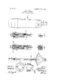
- Fig. 1 represents a side elevation of a hand-lever, toothed sector, sliding detent, and handpiece embodying my invention.
- Fig. 2 is a detached view of the handpiece and associated parts, partly in section.
- Fig. 3 is a cross-section of Fig.
- Fig. 4 is a sectional side detail of the handpiece and associated parts, as shown in Fig. 2, and Fig. 5 is a cross-section of the lever at line C D.
- Figs. 6, 7, and 8 represent details of the construction of the cam-surface forming part of the lever and handpiece.
- 3 is a toothed sect-or adjacent to the handlever, and i is a spring-pressed detent designed to slide longitudinally relative to the lever in a manner to engage with the teeth of the sector in a common way, and 5 is the easing carrying the same, which is secured to the lever.
- the body portion of the lever is a flat bar having its upper end portion forged to a semicircular form 6 and having the shoulders 7 at the junction of the two portions.
- the oppositely-disposed shoulders are provided with cam-surfaces adapted to contact with corresponding surfaces formed at the end of a hollow handpiece 8, adapted to rotate upon the semicircular portion 6 and move longitudinally thereon.
- the hand piece is provided with an interior annular flange 9 near its upper end, and 10 is a disk loosely mounted upon the end of the semicircular portion of the lever and resting upon the annular flange.
- the disk is provided with a lateral opening 11, adapted to receive the hooked end of a rod 12, that has its opposite end connected with the detent I in the usual way.
- a groove 13 is formed in the flat side of the semicircular portion of the lever adapted to receive a part of the body portion of the rod 12 in a manner to prevent the rod and disk rotating with the handpiece, the operation of the device being as follows:
- the handpiece is turned in the direction of the arrows, and the camsurfaces on the shoulders and handpiece operate to move the handpiece longitudinally relative to the lever, and the flange 9 moves the disk and rod correspondingly, and the detent connected therewith is disengaged from the toothed sector, and it remains in that position until the handpiece is turned to a position allowing the cam-surfaces to again come in contact.
- I provide the handpiece with a double set of cam-surfaces to engage with the shoulders, as shown in Fig. 2.
- an adjusting-lever the combination of a lever, a toothed sector adjacent thereto, a spring-pressed detent mounted upon said lever and adapted to engage with said toothed sector, a hollow hand piece rotatably mounted upon said lever, said handpiece having an internal flange surrounding said lever, a disk loosely mounted upon the lever above said flange, means for moving said handpiece longitudinally when it is rotated, and a connection between said disk and said detent.
- an adjusting-lever the combination of a lever, a toothed sector adjacent one end thereof, a spring-pressed detent mounted upon said lever and adapted to engage with said toothed sector, the opposite end of said lever being provided with a longitudinal semicircular portion and cam-shoulders at the junction of the semicircular and body portions thereof, a hollow handpiece rotatably mounted on said semicircular portion and having at one end opposing cam-siiirfaces engaging with said camsl1oulders, and an internal annular flange at its opposite end, a disk loosely mounted upon the lever above said flange, and a rod having a hook at one end engaging with said disk and its opposite end connected with said detent.
- a lever a toothed sector adjacent one end thereof, a s pring-pressed detent mounted upon said lever and adapted to engage with said toothed sector, the opposite end of said lever being provided with a longitudinal semicircular portion having a longitudinally-arranged groove in one side thereof and cam-shoulders at the junction of the semicircular and body portions of the lever, a hollow handpiece rotatably mounted on said semicircular portion and having at one end opposing cam-surfaces engaging with said cam-shoulders, and an in- 1 ternal annular flange at its opposite end, a disk loosely mounted upon the lever above said flange, and a rod seated in said groove and having a hook at one end engaging with said disk and its opposite end engaging with said detent.
Landscapes
- Physics & Mathematics (AREA)
- General Physics & Mathematics (AREA)
- Engineering & Computer Science (AREA)
- Automation & Control Theory (AREA)
- Dental Tools And Instruments Or Auxiliary Dental Instruments (AREA)
Description
PATENTED OCT. 3, 1905 H. J. CASE. ADJUSTING LEVER.
APPLICATION FILED JUNE 26,1905.
UNITED STATES PATENT OFFICE.
HENRY J. CASE, OF OWVASOO, NEW YORK, ASSIGNOR TO INTERNATIONAL HARVESTER COMPANY, A CORPORATION OF NEW JERSEY.
ADJUSTING-LEVER.
Specification of Letters Patent.
Patented Oct. 8, 1905.
Application filed June 26,1905. Serial No. 266,975-
lb u/ZL w/tmn, it nuty concern.-
Be it known that I, HENRY J. CASE, a citizen of the United States, residing at the town of ()wasco, in the county of Cayuga and State of New York, have invented certain new and useful Improvements in Adjusting-Levers, of which the following is a specification, reference being had to the accompanying drawings, forming a part thereof.
My invention relates to adjusting-levers in general of that class designed for use in combination with toothed sector-racks and having a detent adapted to engage with the teeth thereof in a manner to lock the lever against movement, and in particular to the mechanism provided for moving the detent in one direction.
It consists in a hand-lever provided with a hollow rotatable handpiece mounted upon the reduced end thereof and adapted to move longitudinally thereon, said movement caused by opposing contacting cam-surfaces formed upon the respective members, and a connection between said handpiece and the sliding detent, the object of the invention being to provide a mechanism that is simple, strong, and effective and one equally as handy to manipulate whichever direction it is desired to operate the lever. I attain these objects by the mechanism illustrated in the accompanying drawings, in which- Figure 1 represents a side elevation of a hand-lever, toothed sector, sliding detent, and handpiece embodying my invention. Fig. 2 is a detached view of the handpiece and associated parts, partly in section. Fig. 3 is a cross-section of Fig. 2 on line A B. Fig. 4 is a sectional side detail of the handpiece and associated parts, as shown in Fig. 2, and Fig. 5 is a cross-section of the lever at line C D. Figs. 6, 7, and 8 represent details of the construction of the cam-surface forming part of the lever and handpiece.
Similar numerals denote similar parts throughout the several views.
1 represents a rock-shaft upon which a hand-lever 2, is mounted.
3 is a toothed sect-or adjacent to the handlever, and i is a spring-pressed detent designed to slide longitudinally relative to the lever in a manner to engage with the teeth of the sector in a common way, and 5 is the easing carrying the same, which is secured to the lever.
In its preferred form the body portion of the lever is a flat bar having its upper end portion forged to a semicircular form 6 and having the shoulders 7 at the junction of the two portions. The oppositely-disposed shoulders are provided with cam-surfaces adapted to contact with corresponding surfaces formed at the end of a hollow handpiece 8, adapted to rotate upon the semicircular portion 6 and move longitudinally thereon. The hand piece is provided with an interior annular flange 9 near its upper end, and 10 is a disk loosely mounted upon the end of the semicircular portion of the lever and resting upon the annular flange. The disk is provided with a lateral opening 11, adapted to receive the hooked end of a rod 12, that has its opposite end connected with the detent I in the usual way. A groove 13 is formed in the flat side of the semicircular portion of the lever adapted to receive a part of the body portion of the rod 12 in a manner to prevent the rod and disk rotating with the handpiece, the operation of the device being as follows:
To release the detent from engagement with the teeth of the sector, the handpiece is turned in the direction of the arrows, and the camsurfaces on the shoulders and handpiece operate to move the handpiece longitudinally relative to the lever, and the flange 9 moves the disk and rod correspondingly, and the detent connected therewith is disengaged from the toothed sector, and it remains in that position until the handpiece is turned to a position allowing the cam-surfaces to again come in contact. In its preferred form I provide the handpiece with a double set of cam-surfaces to engage with the shoulders, as shown in Fig. 2.
What I claim as my invention, and desire to secure by Letters Patent, is
1. In an adjusting-lever, the combination of a lever, a toothed sector adjacent thereto, a spring-pressed detent mounted upon said lever and adapted to engage with said toothed sector, a hollow hand piece rotatably mounted upon said lever, said handpiece having an internal flange surrounding said lever, a disk loosely mounted upon the lever above said flange, means for moving said handpiece longitudinally when it is rotated, and a connection between said disk and said detent.
2. in an adj Listing-lever, the combination of a lever, a toothed sector adjacent thereto, a spring-pressed detent mounted upon said lever and adapted to engage with said toothed sector, a hollow liant'l piece rotatably mounted upon said lever, said handpiece having an internal flange surrounding said lever, a disk loosely mounted upon the lever above said flange, means for moving said liandpiece longitudinally when it is rotated, and a rod having a hook at one end engaging with said disk and its opposite end connected with said detent.
3 In an adjusting-lever, the combination of a lever, a toothed sector adjacent one end thereof, a spring-pressed detent mounted upon said lever and adapted to engage with said toothed sector, the opposite end of said lever being provided with a longitudinal semicircular portion and cam-shoulders at the junction of the semicircular and body portions thereof, a hollow handpiece rotatably mounted on said semicircular portion and having at one end opposing cam-siiirfaces engaging with said camsl1oulders, and an internal annular flange at its opposite end, a disk loosely mounted upon the lever above said flange, and a rod having a hook at one end engaging with said disk and its opposite end connected with said detent.
4. In an adjusting-lever, the combination of a lever, a toothed sector adjacent one end thereof, a s pring-pressed detent mounted upon said lever and adapted to engage with said toothed sector, the opposite end of said lever being provided with a longitudinal semicircular portion having a longitudinally-arranged groove in one side thereof and cam-shoulders at the junction of the semicircular and body portions of the lever, a hollow handpiece rotatably mounted on said semicircular portion and having at one end opposing cam-surfaces engaging with said cam-shoulders, and an in- 1 ternal annular flange at its opposite end, a disk loosely mounted upon the lever above said flange, and a rod seated in said groove and having a hook at one end engaging with said disk and its opposite end engaging with said detent.
In witness whereof 1 hereto afiix my signature in presence of two witnesses.
l HENRY J. CASE.
Vitnesses:
GEO. W. HENDERSON, i A. M. CHRISTIAN.
Priority Applications (1)
| Application Number | Priority Date | Filing Date | Title |
|---|---|---|---|
| US26697505A US800983A (en) | 1905-06-26 | 1905-06-26 | Adjusting-lever. |
Applications Claiming Priority (1)
| Application Number | Priority Date | Filing Date | Title |
|---|---|---|---|
| US26697505A US800983A (en) | 1905-06-26 | 1905-06-26 | Adjusting-lever. |
Publications (1)
| Publication Number | Publication Date |
|---|---|
| US800983A true US800983A (en) | 1905-10-03 |
Family
ID=2869469
Family Applications (1)
| Application Number | Title | Priority Date | Filing Date |
|---|---|---|---|
| US26697505A Expired - Lifetime US800983A (en) | 1905-06-26 | 1905-06-26 | Adjusting-lever. |
Country Status (1)
| Country | Link |
|---|---|
| US (1) | US800983A (en) |
-
1905
- 1905-06-26 US US26697505A patent/US800983A/en not_active Expired - Lifetime
Similar Documents
| Publication | Publication Date | Title |
|---|---|---|
| US800983A (en) | Adjusting-lever. | |
| US679088A (en) | Snap-hook. | |
| US316810A (en) | Abnee niebel | |
| US1136498A (en) | Bolt-operating mechanism. | |
| US1125325A (en) | Pawl-and-ratchet mechanism. | |
| US652001A (en) | Lock-hinge. | |
| US1116688A (en) | Hand-hook. | |
| US1263099A (en) | Bull-staff. | |
| US1225322A (en) | Door-closing mechanism. | |
| US686372A (en) | Lifting-lever. | |
| US380995A (en) | Henry f | |
| US678252A (en) | Hand-lever. | |
| US862468A (en) | Lever. | |
| US175964A (en) | Improvement in throttle-valve levers | |
| US245959A (en) | Brake-lever | |
| US462327A (en) | Wagon-jack | |
| US720758A (en) | Hand-lever-locking device. | |
| US470494A (en) | Throttle-valve lever | |
| US128819A (en) | Improvement in ratchets | |
| US493364A (en) | lewis | |
| US497641A (en) | Hand-lever | |
| US222492A (en) | Improvement in car-jacks | |
| US187579A (en) | Improvement in wagon-brake levers | |
| US801014A (en) | Coupling device. | |
| US1294783A (en) | Brake-lever ratchet mechanism. |