US8005397B2 - Image forming apparatus - Google Patents
Image forming apparatus Download PDFInfo
- Publication number
- US8005397B2 US8005397B2 US12/130,156 US13015608A US8005397B2 US 8005397 B2 US8005397 B2 US 8005397B2 US 13015608 A US13015608 A US 13015608A US 8005397 B2 US8005397 B2 US 8005397B2
- Authority
- US
- United States
- Prior art keywords
- image forming
- cartridge
- developer cartridge
- forming apparatus
- main body
- Prior art date
- Legal status (The legal status is an assumption and is not a legal conclusion. Google has not performed a legal analysis and makes no representation as to the accuracy of the status listed.)
- Active, expires
Links
Images


Classifications
-
- G—PHYSICS
- G03—PHOTOGRAPHY; CINEMATOGRAPHY; ANALOGOUS TECHNIQUES USING WAVES OTHER THAN OPTICAL WAVES; ELECTROGRAPHY; HOLOGRAPHY
- G03G—ELECTROGRAPHY; ELECTROPHOTOGRAPHY; MAGNETOGRAPHY
- G03G15/00—Apparatus for electrographic processes using a charge pattern
- G03G15/22—Apparatus for electrographic processes using a charge pattern involving the combination of more than one step according to groups G03G13/02 - G03G13/20
- G03G15/32—Apparatus for electrographic processes using a charge pattern involving the combination of more than one step according to groups G03G13/02 - G03G13/20 in which the charge pattern is formed dotwise, e.g. by a thermal head
- G03G15/326—Apparatus for electrographic processes using a charge pattern involving the combination of more than one step according to groups G03G13/02 - G03G13/20 in which the charge pattern is formed dotwise, e.g. by a thermal head by application of light, e.g. using a LED array
-
- G—PHYSICS
- G03—PHOTOGRAPHY; CINEMATOGRAPHY; ANALOGOUS TECHNIQUES USING WAVES OTHER THAN OPTICAL WAVES; ELECTROGRAPHY; HOLOGRAPHY
- G03G—ELECTROGRAPHY; ELECTROPHOTOGRAPHY; MAGNETOGRAPHY
- G03G15/00—Apparatus for electrographic processes using a charge pattern
- G03G15/04—Apparatus for electrographic processes using a charge pattern for exposing, i.e. imagewise exposure by optically projecting the original image on a photoconductive recording material
- G03G15/04036—Details of illuminating systems, e.g. lamps, reflectors
- G03G15/04045—Details of illuminating systems, e.g. lamps, reflectors for exposing image information provided otherwise than by directly projecting the original image onto the photoconductive recording material, e.g. digital copiers
- G03G15/04054—Details of illuminating systems, e.g. lamps, reflectors for exposing image information provided otherwise than by directly projecting the original image onto the photoconductive recording material, e.g. digital copiers by LED arrays
-
- G—PHYSICS
- G03—PHOTOGRAPHY; CINEMATOGRAPHY; ANALOGOUS TECHNIQUES USING WAVES OTHER THAN OPTICAL WAVES; ELECTROGRAPHY; HOLOGRAPHY
- G03G—ELECTROGRAPHY; ELECTROPHOTOGRAPHY; MAGNETOGRAPHY
- G03G15/00—Apparatus for electrographic processes using a charge pattern
- G03G15/06—Apparatus for electrographic processes using a charge pattern for developing
- G03G15/08—Apparatus for electrographic processes using a charge pattern for developing using a solid developer, e.g. powder developer
- G03G15/0822—Arrangements for preparing, mixing, supplying or dispensing developer
- G03G15/0848—Arrangements for testing or measuring developer properties or quality, e.g. charge, size, flowability
- G03G15/0849—Detection or control means for the developer concentration
- G03G15/0855—Detection or control means for the developer concentration the concentration being measured by optical means
-
- G—PHYSICS
- G03—PHOTOGRAPHY; CINEMATOGRAPHY; ANALOGOUS TECHNIQUES USING WAVES OTHER THAN OPTICAL WAVES; ELECTROGRAPHY; HOLOGRAPHY
- G03G—ELECTROGRAPHY; ELECTROPHOTOGRAPHY; MAGNETOGRAPHY
- G03G15/00—Apparatus for electrographic processes using a charge pattern
- G03G15/06—Apparatus for electrographic processes using a charge pattern for developing
- G03G15/08—Apparatus for electrographic processes using a charge pattern for developing using a solid developer, e.g. powder developer
- G03G15/0822—Arrangements for preparing, mixing, supplying or dispensing developer
- G03G15/0865—Arrangements for supplying new developer
-
- G—PHYSICS
- G03—PHOTOGRAPHY; CINEMATOGRAPHY; ANALOGOUS TECHNIQUES USING WAVES OTHER THAN OPTICAL WAVES; ELECTROGRAPHY; HOLOGRAPHY
- G03G—ELECTROGRAPHY; ELECTROPHOTOGRAPHY; MAGNETOGRAPHY
- G03G15/00—Apparatus for electrographic processes using a charge pattern
- G03G15/06—Apparatus for electrographic processes using a charge pattern for developing
- G03G15/08—Apparatus for electrographic processes using a charge pattern for developing using a solid developer, e.g. powder developer
- G03G15/0822—Arrangements for preparing, mixing, supplying or dispensing developer
- G03G15/0877—Arrangements for metering and dispensing developer from a developer cartridge into the development unit
- G03G15/0881—Sealing of developer cartridges
- G03G15/0886—Sealing of developer cartridges by mechanical means, e.g. shutter, plug
-
- G—PHYSICS
- G03—PHOTOGRAPHY; CINEMATOGRAPHY; ANALOGOUS TECHNIQUES USING WAVES OTHER THAN OPTICAL WAVES; ELECTROGRAPHY; HOLOGRAPHY
- G03G—ELECTROGRAPHY; ELECTROPHOTOGRAPHY; MAGNETOGRAPHY
- G03G15/00—Apparatus for electrographic processes using a charge pattern
- G03G15/06—Apparatus for electrographic processes using a charge pattern for developing
- G03G15/08—Apparatus for electrographic processes using a charge pattern for developing using a solid developer, e.g. powder developer
- G03G15/0822—Arrangements for preparing, mixing, supplying or dispensing developer
- G03G15/0887—Arrangements for conveying and conditioning developer in the developing unit, e.g. agitating, removing impurities or humidity
- G03G15/0891—Arrangements for conveying and conditioning developer in the developing unit, e.g. agitating, removing impurities or humidity for conveying or circulating developer, e.g. augers
- G03G15/0893—Arrangements for conveying and conditioning developer in the developing unit, e.g. agitating, removing impurities or humidity for conveying or circulating developer, e.g. augers in a closed loop within the sump of the developing device
-
- G—PHYSICS
- G03—PHOTOGRAPHY; CINEMATOGRAPHY; ANALOGOUS TECHNIQUES USING WAVES OTHER THAN OPTICAL WAVES; ELECTROGRAPHY; HOLOGRAPHY
- G03G—ELECTROGRAPHY; ELECTROPHOTOGRAPHY; MAGNETOGRAPHY
- G03G21/00—Arrangements not provided for by groups G03G13/00 - G03G19/00, e.g. cleaning, elimination of residual charge
- G03G21/16—Mechanical means for facilitating the maintenance of the apparatus, e.g. modular arrangements
- G03G21/1604—Arrangement or disposition of the entire apparatus
-
- G—PHYSICS
- G03—PHOTOGRAPHY; CINEMATOGRAPHY; ANALOGOUS TECHNIQUES USING WAVES OTHER THAN OPTICAL WAVES; ELECTROGRAPHY; HOLOGRAPHY
- G03G—ELECTROGRAPHY; ELECTROPHOTOGRAPHY; MAGNETOGRAPHY
- G03G21/00—Arrangements not provided for by groups G03G13/00 - G03G19/00, e.g. cleaning, elimination of residual charge
- G03G21/16—Mechanical means for facilitating the maintenance of the apparatus, e.g. modular arrangements
- G03G21/1642—Mechanical means for facilitating the maintenance of the apparatus, e.g. modular arrangements for connecting the different parts of the apparatus
- G03G21/1647—Mechanical connection means
-
- G—PHYSICS
- G03—PHOTOGRAPHY; CINEMATOGRAPHY; ANALOGOUS TECHNIQUES USING WAVES OTHER THAN OPTICAL WAVES; ELECTROGRAPHY; HOLOGRAPHY
- G03G—ELECTROGRAPHY; ELECTROPHOTOGRAPHY; MAGNETOGRAPHY
- G03G21/00—Arrangements not provided for by groups G03G13/00 - G03G19/00, e.g. cleaning, elimination of residual charge
- G03G21/16—Mechanical means for facilitating the maintenance of the apparatus, e.g. modular arrangements
- G03G21/18—Mechanical means for facilitating the maintenance of the apparatus, e.g. modular arrangements using a processing cartridge, whereby the process cartridge comprises at least two image processing means in a single unit
- G03G21/1839—Means for handling the process cartridge in the apparatus body
-
- G—PHYSICS
- G03—PHOTOGRAPHY; CINEMATOGRAPHY; ANALOGOUS TECHNIQUES USING WAVES OTHER THAN OPTICAL WAVES; ELECTROGRAPHY; HOLOGRAPHY
- G03G—ELECTROGRAPHY; ELECTROPHOTOGRAPHY; MAGNETOGRAPHY
- G03G2221/00—Processes not provided for by group G03G2215/00, e.g. cleaning or residual charge elimination
- G03G2221/16—Mechanical means for facilitating the maintenance of the apparatus, e.g. modular arrangements and complete machine concepts
- G03G2221/1636—Mechanical means for facilitating the maintenance of the apparatus, e.g. modular arrangements and complete machine concepts for the exposure unit
-
- G—PHYSICS
- G03—PHOTOGRAPHY; CINEMATOGRAPHY; ANALOGOUS TECHNIQUES USING WAVES OTHER THAN OPTICAL WAVES; ELECTROGRAPHY; HOLOGRAPHY
- G03G—ELECTROGRAPHY; ELECTROPHOTOGRAPHY; MAGNETOGRAPHY
- G03G2221/00—Processes not provided for by group G03G2215/00, e.g. cleaning or residual charge elimination
- G03G2221/16—Mechanical means for facilitating the maintenance of the apparatus, e.g. modular arrangements and complete machine concepts
- G03G2221/1651—Mechanical means for facilitating the maintenance of the apparatus, e.g. modular arrangements and complete machine concepts for connecting the different parts
- G03G2221/1654—Locks and means for positioning or alignment
Definitions
- the present invention relates to an image forming apparatus equipped with an exposure member, which is movable toward and away from a photosensitive element.
- a photosensitive drum (photosensitive element) is electrically charged and this electrically charged photosensitive drum is then irradiated with light so that the electric potential of the irradiated area lowers to form an electrostatic latent image on the photosensitive drum.
- developer is supplied onto this latent image to form a developer image, which is then transferred onto a paper so that a predetermined image is formed on the paper.
- Japanese Laid-open Patent Publication No. 2003-112446 discloses an image forming apparatus, which is equipped with an LED head for emitting light and irradiating a photosensitive drum with the light, and a top cover supporting the LED head and pivotally connected to the main body of the apparatus.
- opening the top cover causes the LED head to be retracted from the photosensitive drum, whereas closing the top cover causes the LED head to be positioned in a predetermined position with respect to the photosensitive drum.
- the top cover is not required for positioning the LED head with respect to the photosensitive element.
- the LED head is pressed and urged by the top cover toward the photosensitive element to carry out the positioning of the LED head. Therefore, the top cover does not provide a stable and accurate pressing force, which may result in a difficulty in accurate positioning between the LED head and the photosensitive element.
- the present invention seeks to provide an image forming apparatus in which accurate positioning of the exposure member to the photosensitive element is readily performed while the internal space of the apparatus can be used effectively.
- an image forming apparatus comprises: a process unit including a photosensitive element; an exposure member configured to expose the photosensitive element to light to form an electrostatic latent image on the photosensitive element; a main body casing configured to accommodate the process unit and the exposure member; and a developer cartridge configured to supply developer to the process unit.
- the developer cartridge is configured to be attached to and removed from the process unit.
- the exposure member is positioned between the photosensitive element and the developer cartridge so as to be attached and movable between a first position in which the photosensitive element is exposed to light by the exposure member and a second position in which the exposure member is away from the photosensitive element.
- the developer cartridge has a pressing portion, and the pressing portion is configured to press the exposure member toward the first position with the developer cartridge being attached to the main body casing.
- the developer cartridge is attached to the process cartridge with a relatively high positioning accuracy. Therefore, the exposure member is accurately pressed by the pressing portion of the developer cartridge toward the photosensitive element. As a result, it is possible to readily perform an accurate positioning of the exposure member relative to the photosensitive element.
- the moving passage (trajectory) of the exposure member can be shortened to such an extent that the pressing portion of the developer cartridge causes the exposure member to move to the photosensitive element. This makes it possible to effectively use the internal space of the image forming apparatus.
- the pressing portion of the developer cartridge presses the exposure member and causes the exposure member to move from the second position to the first position, an accurate positioning of the exposure member relative to the photosensitive element is readily performed while the internal space of the image forming apparatus can be used effectively.
- FIG. 1 is a perspective view of a printer as an image forming apparatus according to one preferred embodiment of the present invention
- FIG. 2 is a perspective view of the printer illustrating a state where a toner cartridge is removed from the printer;
- FIGS. 3A and 3B are vertical sections of the printer, in which FIG. 3A illustrates a state where the toner cartridge is attached to the printer, and FIG. 3B illustrates a state where the toner cartridge is ready for removal from the printer;
- FIGS. 4A and 4B are views showing a process cartridge of FIGS. 3A and 3B , in which FIG. 4A is a sectional view of the process cartridge, and FIG. 4B is a sectional view taken along the line X-X of FIG. 4A ;
- FIGS. 5A and 5B are side views showing the toner cartridge and its operating portion, in which FIG. 5A illustrates a state where the operating portion is in an open position, and FIG. 5B illustrates a state where the operating portion is in a closed position;
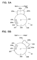
- FIGS. 6A to 6D are views showing the toner cartridge, in which FIG. 6A is a rear view illustrating a state where the operating portion is in the open position, FIG. 6B is a sectional view of FIG. 6A , FIG. 6C is a rear view illustrating a state where the operating portion is in the closed position, and FIG. 6D is a sectional view of FIG. 6C ;
- FIGS. 7A and 7B are perspective views of the cartridge body, in which FIG. 7A shows the cartridge body in the open position, and FIG. 7B shows the cartridge body in the closed position;
- FIGS. 8A to 8C are views showing details of an LED head, in which FIG. 8A is a view as seen from a direction of arrow Y of FIG. 4 A, FIG. 8B is a sectional view taken along the line Z-Z of FIG. 8A and illustrating a state where the LED head is in a retracted position, and FIG. 8C is a sectional view taken along the line Z-Z of FIG. 8A and illustrating a state where the LED head is in a light-exposure position;
- FIG. 9 is a vertical section of the printer illustrating a state where the process cartridge is removed from the main body casing
- FIGS. 10A and 10B are vertical sections of the printer illustrating a detachment passage for the cartridge body, in which FIG. 10A shows a starting position for attachment of the cartridge body, and FIG. 10B shows an intermediate position at which the cartridge body is halfway through the attachment; and
- FIGS. 11A and 11B are vertical sections of the printer illustrating the detachment passage for the cartridge body, in which FIG. 11A illustrates a state where the cartridge body is inserted farther from the position of FIG. 10B , and FIG. 11B shows the cartridge body in an attached position.
- an image forming apparatus is provided as an upright-type printer 1 , which has a relatively short length in the front-rear direction compared to the right-and-left direction and the height of which is tall.
- the printer 1 has a main body casing 2 .
- a top cover 3 is provided at an upper part of the main body casing 2
- a front cover 4 is provided at a front upper part of the main body casing 2 .
- Provided at a front lower part of the main body casing 2 is an attachment opening 5 , through which the attachment and detachment of a process cartridge 14 and a toner cartridge 20 are performed.
- the process cartridge 14 constitutes an image forming unit 8 to be described later
- the toner cartridge 20 is an example of a developer cartridge.
- the front cover 4 constitutes a part of the main body casing 2 .
- a sheet feed tray 6 stores a stack of papers (or sheets) (not shown) as recording sheets in a state where the papers are placed substantially in an upright position, and the feeder unit 7 pulls a paper (not shown) downward from the sheet feed tray 6 and feeds out the paper to the image forming unit 8 .
- the image forming unit 8 forms an image on the paper that is carried from the feeder unit 7 .
- the sheet output tray 9 receives the paper on which the image is formed by the image forming unit 8 , and stacks and stores sheets of paper substantially in an upright position.
- the sheet feed tray 6 is attached to and detachable from the rear side of the main body casing 2 .
- the sheet feed tray 6 can be pulled out upward from the main body casing 2 .
- the rear end portion of the top cover 3 is pivotally connected to the upper end portion of the sheet feed tray 6 so that when the front end portion of the top cover 3 is lifted in the upward direction, a sheet loading opening opens at the upper part of the sheet feed tray 6 .
- a sheet pressure plate 10 is pivotally supported in the sheet feed tray 6 so as to press the lower end of the stack of papers toward a sheet feed opening 6 A provided at the front lower part of the sheet feed tray 6 .
- the feeder unit 7 is positioned adjacent to the sheet feed opening 6 A at the front lower part of the sheet feed tray 6 .
- the feeder unit 7 includes a separation roller 12 and a separation pad 11 between which the lower end of the paper (i.e., leading edge of the paper along the conveyance direction) is fed so that the paper is separated and fed on one-by-one basis, and a registration roller 13 with which the leading edge of the paper that is conveyed from the separation roller 12 is brought into contact so that the paper is temporarily constrained and thereafter conveyed upward to the image forming unit 8 .
- the registration roller 13 is positioned just above the separation roller 12 , and conveys the paper upward to the image forming unit 8 .
- the image forming unit 8 at least includes a process cartridge 14 and a fixing device 15 .
- the process cartridge 14 is attachable to the main body casing 2 through the attachment opening 5 of the main body casing 2 as shown in FIGS. 1 and 2 , and positioned below the sheet output tray 9 . See FIG. 3A .
- the fixing device 15 is installed in advance in an installation space between the sheet output tray 9 and the sheet feed tray 6 .
- the fixing device 15 is positioned above the process cartridge 14 .
- the sheet output tray 9 is positioned in the main body casing 2 at the front side of the main body casing 2 with an installation space for the fixing device 15 , etc. being left between the sheet output tray 9 and the sheet feed tray 6 .
- the bottom of the sheet output tray 9 is positioned higher than the bottom portion of the sheet feed tray 6 .
- an installation space for the process cartridge 14 which constitutes the image forming unit 8 .
- the lower end portion of the front cover 4 is pivotally connected to the lower end portion of the sheet output tray 9 .
- the front side of the sheet output tray 9 opens so that the papers stored in the sheet output tray 9 can be readily removed.
- the upper end of the sheet output tray 9 contains a sheet output opening 9 A whose lateral width is greater than that of the paper (i.e., width of the paper in the direction orthogonal to the sheet conveyance direction), so that sheets of paper can be removed also through this opening 9 A.
- a recess 16 is formed in the rear wall of the sheet output tray 9 at a vertically intermediate portion thereof.
- the recess 16 dents toward a space above the fixing device 15 .
- a pair of sheet ejection rollers 17 , 17 for drawing a paper into the sheet output tray 9 .
- a sheet guide 18 is formed in the main body casing 2 .
- a conveyor belt 40 is provided in the recess 16 so as to hold the leading edge of the paper and convey the same in the forward direction.
- the conveyor belt 40 is provided at a front side of and adjacent to the sheet ejection rollers 17 , 17 .
- a plurality of projections are formed on the surface of the conveyor belt 40 such that the leading edge of the paper is properly held and conveyed to the lower portion of the sheet output tray 9 .
- the process cartridge 14 includes the toner cartridge 20 which is detachably mounted to the cartridge body 19 .
- the process cartridge 14 also includes a toner feed auger 21 , a supply roller 22 , a developing roller 23 , a photosensitive drum 24 , a charger 25 , and a transfer roller 26 , which are installed in advance in the cartridge body 19 .
- the cartridge body 19 including the photosensitive drum 24 corresponds to an example of the process unit.
- the toner cartridge 20 includes an inner cylinder 20 A in the form of a hollow cylinder, and an outer cylinder 20 B which is rotatable relative to the inner cylinder 20 A and functions as a first shutter.
- a toner supply opening 201 is formed at one end of the inner cylinder 20 A.
- the toner supply opening 201 is an example of an opening through which toner is supplied from the toner cartridge 20 into a development chamber DR that is defined in the cartridge body 19 .
- Formed at the other end of the inner cylinder 20 A is a toner return opening 202 through which toner is returned from the development chamber DR to the inner cylinder 20 A.
- An agitator 42 is rotatably supported in the inner cylinder 20 A.
- the agitator 42 has a plurality of blades whose shapes are designed to agitate toner and feed the toner in one direction of the inner cylinder 20 A.
- the agitator 42 is driven to rotate when a drive source (not shown) supplies a driving force to the agitator 42 .
- a rotation shaft 42 A of the agitator 42 penetrates through and protrudes outward from both ends (right and left ends) of the inner cylinder 20 A and the outer cylinder 20 B.
- Protrusions 205 , 205 are formed offset from the center of both ends of the inner cylinder 20 A. The protrusions 205 , 205 protrude outward along an axial direction of the rotation shaft 42 A of the agitator 42 .
- the outer cylinder 20 B includes a tonner supply opening 203 and a toner return opening 204 each corresponding to the toner supply opening 201 and the toner return opening 202 of the inner cylinder 20 A. Further, as shown in FIGS. 5A and 5B , an operating portion 206 and engagement protrusions 207 , 207 (only one is shown in the figures) are provided on the outer periphery of the outer cylinder 20 B.
- the operating portion 206 includes a pressing wall 206 a as an example of a pressing portion in the form of a semi-cylindrical surface, a holding wall 206 b in the form of a semi-cylindrical surface and positioned ahead and opposite of the pressing wall 206 a , and a pair of side walls 206 c (see FIG. 1 ) connecting the right and left ends of the pressing wall 206 a with the right and left ends of the holding wall 206 b .
- the holding wall 206 b is held by a user. When the user holds and operates the holding wall 206 b , as seen in FIGS.
- the toner supply opening 201 and the toner return opening 202 of the inner cylinder 20 A are opened or closed by the outer cylinder 20 B which functions as the first shutter.
- the operating portion 206 is rotated to the upward position of the outer cylinder 20 B (hereinafter referred to as an “open position”) as shown in FIG. 5A
- the tonner supply opening 201 and the toner return opening 202 of the inner cylinder 20 A are opened to the outside via the toner supply opening 203 and the toner return opening 204 of the outer cylinder 20 B as shown in FIG. 6B .
- the operating portion 206 when the operating portion 206 is rotated to a position that is slightly forward from the open position (hereinafter referred to as a “closed position”) as shown in FIG. 5B , the tonner supply opening 201 and the toner return opening 202 of the inner cylinder 20 A are closed by the outer peripheral wall of the outer cylinder 20 B as shown in FIG. 6D .
- a logo 14 A formed on the outer peripheral surface of the outer cylinder 20 B can be seen from the front side of the printer 1 .
- Operating the holding wall 206 b causes the pressing wall 206 a to move substantially in the front-rear direction.
- an LED head 29 that is slidably supported in the main body casing 2 is pressed substantially in the rearward direction by the pressing wall 206 a .
- the pressing wall 206 a is positioned in a pressing position where the pressing wall 206 a presses the LED head 29 to position the LED head 29 in a light-exposure position (first position) to be described later.
- the pressing wall 206 a when the operating portion 206 is rotated to the closed position, the pressing wall 206 a is positioned in a disengaged position where the pressing wall 206 a is disengaged from LED head 29 .
- the term “with the toner cartridge 20 being attached to the cartridge body 19 ” indicates that both the cartridge body 19 and the toner cartridge 20 are attached to the main body casing 2 . More specifically, when the outer cylinder 20 B closes the toner supply opening 201 and the toner return opening 202 of the inner cylinder 20 A, the pressing wall 206 a is positioned away from the LED head 29 . The sliding structure of the LED head 29 will be described later.
- the engagement protrusions 207 , 207 are integrally formed on the outer periphery of the outer cylinder 20 B.
- Each engagement protrusion 207 protrudes radially outward from the outer peripheral surface of the outer cylinder 20 B, and is engageable with a corresponding engagement opening 195 a (see FIGS. 7A and 7B ) formed in a rotary wall 195 of the cartridge body 19 to be described later.
- the engagement protrusions 207 , 207 are provided in pair in the right-and-left direction slightly below the toner supply opening 203 and the toner return opening 204 .
- an arcuate elongate hole 208 a is formed in each end wall 208 of the outer cylinder 20 B so that the protrusion 205 of the inner cylinder 20 A engages therein. This allows a relative rotation of the outer cylinder 20 B with respect to the inner cylinder 20 A as well as restricts the rotation range of the outer cylinder 20 B.
- sponge members 203 A, 204 A are provided on the outer peripheral surface of the outer cylinder 20 B around the toner supply opening 203 and the toner return opening 204 .
- sponge members 203 B, 204 B as an example of a restriction member are also provided on the inner peripheral surface of the outer cylinder 20 B around the toner supply opening 203 and the toner return opening 204 .
- sponge members 201 A, 202 A are provided on the outer peripheral surface of the inner cylinder 20 A around the toner supply opening 201 and the toner return opening 202 . Therefore, as seen in FIG.
- these sponge members provide seals to prevent leakage of toner upon supplying the toner from the inner cylinder 20 A to the development chamber DR. Because of the frictional force generated by the contact between the sponge members 201 A, 202 A of the inner cylinder 20 A and the sponge members 203 B, 204 B of the outer cylinder 20 B, the outer cylinder 20 B is positioned with respect to the main body casing 2 through the inner cylinder 20 A and the cartridge body 19 . Accordingly, the outer cylinder 20 B is positioned in the open position. As described later, urging force of a retracting spring 400 also prevents the outer cylinder 20 B from being displaced from the open position.
- the sponge members 203 B, 204 B provided on the inner peripheral surface of the outer cylinder 20 B are shown as if they are at a distance from the inner cylinder 20 A; however, the sponge members 203 B, 204 B are actually in contact with the inner cylinder 20 A. Accordingly, the outer cylinder 20 B is positioned in the closed position.
- the mechanism for positioning the outer cylinder 20 B with respect to the inner cylinder 20 A (main body casing 2 ) in the open position or the closed position is not limited to the above mechanism using the sponge members.
- a locking block urged by a spring may be inserted into a recess formed in the inner cylinder 20 A.
- the toner cartridge 20 as described above is arranged closer to the sheet output tray 9 than the developing roller 23 .
- the toner cartridge 20 is attached to the cartridge body 19 such that the rotation shaft 42 A of the agitator 42 is positioned ahead of the front surface of the front cover 4 .
- the sheet output tray 9 is arranged more inward than the toner cartridge 20 (i.e., on the light-exposure position side of the LED head 29 in a direction in which the LED head 29 is movable, e.g., slidable).
- the arrangement of the LED head 29 between the photosensitive drum 24 and the toner cartridge 20 allows the toner cartridge 20 to protrude outward from the main body casing 2 .
- the toner cartridge 20 is positioned on the light-exposure position side of the LED head 29 in the direction in which the LED head 29 is slidable such that the pressing wall 206 a is in the disengaged position. Therefore, the pressing wall 206 a is brought into contact with the LED head 29 by using a simple mechanism, which leads to effective use of the internal space of the printer 1 .
- the cartridge body 19 includes therein an undercut 191 along which the LED head 29 is movable in the right-and-left directions.
- the undercut 191 is defined between right and left side walls 192 , 192 formed with engagement grooves 192 a , 192 a as an example of an engagement portion along which the LED head 29 is slidable to and positioned in the light-exposure position (where the photosensitive drum 24 is exposed to light by the LED head 29 ).
- each of the engagement grooves 192 a , 192 a is shaped linearly and permits a sliding engagement with a slide protrusion 29 a that is formed on the side surface of the LED head 29 as shown in FIG. 4A .
- a taper-shaped guide surface 192 b is formed at the front end of the engagement groove 192 a to facilitate inserting the slide protrusion 29 a of the LED head 29 into the corresponding engagement groove 192 a.
- a semi-cylindrical recess 193 is formed in the cartridge body 19 , to which the toner cartridge 20 is attached.
- the recess 193 is defined between right and left side walls 194 , 194 formed with guide grooves 14 B, 14 B.
- the guide grooves 14 B, 14 B slidably support the protrusions 205 , 205 and the rotation shaft 42 A of the agitator 42 ( FIG. 4B ) which protrude from both ends of the toner cartridge 20 .
- the guide grooves 14 B, 14 B are substantially parallel to the engagement grooves 192 a , 192 a , so that the attachment and detachment directions of the toner cartridge 20 to and from the cartridge body 19 are substantially equal to the sliding directions of the LED head 29 .
- a taper-shaped guide surface 14 C is formed at the front end of each guide groove 14 B to facilitate inserting the protrusion 205 and the rotation shaft 42 A into the corresponding guide groove 14 B.
- An elastically deformable retaining spring 14 D is provided at the rear side of each guide groove 14 B.
- a toner supply opening 193 a as an example of a supply opening and a toner return opening 193 b as an example of a return opening are formed in the recess 193 of the cartridge body 19 .
- the toner supply opening 193 a and the toner return opening 193 b are in communication with the development chamber DR ( FIG. 4B ) and correspond to the toner supply opening 203 and the toner return opening 204 of the outer cylinder 20 B.
- the recess 193 is provided with a rotary wall 195 as an example of a second shutter, which is slidable (rotatable) to open and close the toner supply opening 193 a and the toner return opening 193 b .
- a pair of engagement holes 195 a , 195 a are formed in the rotary wall 195 at predetermined positions, and arcuate grooves 193 c , 193 c as an example of a groove are formed in the sliding surface of the recess 193 on which the rotary wall 195 slides.
- the arcuate grooves 193 c , 193 c allow the sliding movement of the engagement protrusions 207 , 207 protruding from the engagement holes 195 a , 195 a.
- toner stored in the toner cartridge 20 is carried to one end of the toner cartridge 20 by the agitator 42 .
- the agitator 42 supplies the toner that has been carried to the one end of the toner cartridge 20 , through the toner supply opening 201 formed at the one end of the toner cartridge 20 to the development chamber DR defined in the cartridge body 19 .
- the toner introduced into the development chamber DR is carried to the other end of the toner cartridge 20 by the toner feed auger 21 . Therefore, toner is uniformly supplied on the surface of the supply roller 22 along the axial direction of the supply roller 22 .
- the toner carried to the other end of the toner cartridge 20 within the development chamber DR is returned to the toner cartridge 20 through the toner return opening 202 formed in the other end of the toner cartridge 20 .
- the toner that is supplied to the surface of the supply roller 22 makes a frictional contact with the developing roller 23 and is charged positively. Therefore, the toner adheres and is deposited on the surface of the developing roller 23 .
- a doctor blade 41 regulates the deposited toner on the developing roller 23 to a thin layer having a constant thickness.
- the photosensitive drum 24 includes a photosensitive layer having positive charge characteristics.
- a charger 25 When a charger 25 generates and applies a corona discharge from a charge wire made of, e.g., tungsten, the photosensitive layer formed on the surface of the photosensitive drum 24 is uniformly charged to the positive polarity.
- the LED head 29 supported in the main body casing 2 then exposes the positively charged photosensitive layer on the photosensitive drum 24 to light based on image data. This exposure process lowers the potential of a light-exposed area on the photosensitive layer, so that an electrostatic latent image associated with the image data is formed on the photosensitive drum 24 .
- Toner positively charged and carried on the developing roller 23 is attracted to the latent image that is formed on the photosensitive layer of the photosensitive drum 24 .
- a toner image is formed on the photosensitive layer of the photosensitive drum 24 .
- a paper is conveyed along a sheet conveyance passage and passes between the photosensitive drum 24 which carries the toner image on the photosensitive layer and a transfer roller 26 , during which the toner image is transferred on the paper.
- the transfer roller 26 includes a roller shaft, which is made of metal and covered with a conductive rubber material. When a transfer bias is applied to the transfer roller 26 , the toner image formed on the photosensitive drum 24 is transferred to the paper.
- the LED head 29 as an example of an exposure member has a plurality of light-emitting diodes (LEDs) (not shown) arranged in a row along the axial direction of the photosensitive drum 24 so that turning on/off each LED based on predetermined data performs exposure of the photosensitive drum 24 to form an electrostatic latent image on the photosensitive drum 24 .
- the LED head 29 is arranged between the toner cartridge 20 and the lower end of the sheet output tray 9 , and movable in a direction across a plane connecting the sheet output tray 9 and the toner cartridge 20 . As best seen in FIG.
- the LED head 29 is provided with the slide protrusion 29 a as described above, and a spring biased portion 29 b formed on the outside (in the right-and-left direction) of the slide protrusion 29 a on each side (only left side is shown in the figure), and a buffer spring 29 d and an abutment member 29 e on the front surface 29 c of the LED head 29 .
- the spring biased portion 29 b is rectangularly shaped, and as seen in FIGS. 8B and 8C , the spring biased portion 29 b is always urged substantially in the frontward direction by a retracting spring 400 to be described later.
- the spring biased portion 29 b is formed such that the vertical height thereof is greater than that of the slide protrusion 29 a . Therefore, the spring biased portion 29 b reliably receives the urging force of the retracting spring 400 .
- the buffer spring 29 d is positioned between the LED head 29 and the abutment member 29 e .
- the buffer spring 29 d absorbs a shock and protects the LED head 29 when the operating portion 206 is brought into contact with the abutment member 29 e.
- the buffer spring 29 d also absorbs a play (backlash) caused between the slide protrusion 29 a of the LED head 29 and the engagement groove 192 a for guiding the slide protrusion 29 a . Therefore, it is possible to perform accurate positioning of the LED head 29 with respect to the photosensitive drum 24 .
- a support panel 300 is provided for each of right and left side walls 2 a of the main body casing 2 .
- the support panels 300 , 300 define the moving passage of the LED head 29 and the moving passage of the cartridge body 19 .
- Each support panel 300 is positioned near the attachment opening 5 of the main body casing 2 , and has a linear guide groove 301 for slidably guiding the slide protrusion 29 a of the LED head 29 and an arcuate guide groove 302 for defining the moving passage of the cartridge body 19 .
- each guide groove 301 has a width such that a predetermined sized play is formed when the slide protrusion 29 a of the LED head 29 is positioned in the guide groove 301 .
- the guide groove 301 guides the slide protrusion 29 a to the engagement groove 192 a of the cartridge body 19 ( FIGS. 7A and 7B ).
- the side wall 2 a is positioned outside of the guide groove 301 .
- the side wall 2 a has a support groove 2 b as an example of a guide portion along which the spring biased portion 29 b of the LED head 29 is slidably guided.
- the retracting spring 400 is mounted on the rear end surface of the support groove 2 b .
- the retracting spring 400 always urges the spring biased portion 29 b of the LED head 29 in the forward direction, so that when the LED head 29 is not pressed by the operating portion 206 of the toner cartridge 20 , the retracting spring 400 causes the LED head 29 to be positioned in a retracted position (second position).
- the support groove 2 b is formed in the side wall 2 a of the main body casing 2 .
- the present invention is not limited to this specific embodiment.
- the support panel 300 maybe provided with ribs between which a support groove is formed.
- the retracted position indicates a position where the LED head 29 is retracted or positioned away from the photosensitive drum 24 for a predetermined distance.
- the LED head 29 does not interfere with the cartridge body 19 moving along the guide grooves 302 , 302 as an example of an attachment guide.
- the retracting spring 400 is set to provide less urging force than the buffer spring 29 d does. Therefore, when the LED head 29 is pressed by the operating portion 206 , the retracting spring 400 reliably contracts to allow a smooth movement of the LED head 29 .
- the LED head 29 Since the LED head 29 is slidably supported along the guide grooves 301 , 301 formed in the main body casing 2 and the engagement grooves 192 a , 192 a formed in the cartridge body 19 , the LED head 29 is movable between the light-exposure position as shown in FIG. 3 A and the retracted position as shown in FIG. 3B . In the light-exposure position of FIG. 3A , the LED head 29 is positioned between the photosensitive drum 24 and the operating portion 206 of the toner cartridge 20 .
- the guide grooves 302 , 302 extend gradually arcuately upward from the front side toward the rear side of the main body casing 2 , and a rotation shaft 24 A of the photosensitive drum 24 ( FIGS. 7A and 7B ) that protrudes outward through both side walls 192 of the cartridge body 19 is slidably engaged with the guide grooves 302 , 302 .
- a taper-shaped guide surface 302 a is formed at the front end of each guide groove 302 to facilitate inserting the rotation shaft 24 A of the photosensitive drum 24 into the corresponding guide groove 302 .
- An elastically deformable retaining spring 302 b is provided at the rear side of each guide groove 302 .
- the cartridge body 19 is mounted to the main body casing 2 .
- the main body casing 2 is provided, on each side, with a restriction wall 2 h , which is partly engageable with the lower end of the process cartridge 14 to prevent the process cartridge 14 that has been attached to the main body casing 2 from accidentally becoming detached from the main body casing 2 . Therefore, the process cartridge 14 is stably attached to the main body casing 2 by the restriction walls 2 h , 2 h and the retaining springs 302 b , 302 b.
- the fixing device 15 includes a heating roller 30 and a pressure roller 31 which are positioned oppositely and rotate to pinch and convey a paper toward the sheet output tray 9 , and a pair of conveyance rollers 32 , 32 .
- the pair of conveyance rollers 32 , 32 are positioned downstream of the sheet conveyance passage from the heating roller 30 and the pressure roller 31 .
- These conveyance rollers 32 , 32 feed the paper along the sheet guide 18 to the sheet ejection rollers 17 , 17 that are provided at the recess 16 of the sheet output tray 9 .
- a paper on which a toner image has been transferred between the photosensitive drum 24 and the transfer roller 26 in the process cartridge 14 is conveyed and passes between the heating roller 30 and the pressure roller 31 provided in the fixing device 15 .
- the toner image formed on the paper is thermally fixed by the heating roller 30 .
- the sheet conveyance passage along which a paper is conveyed extends from the sheet feed tray 6 toward the sheet output tray 9 .
- the sheet conveyance passage has a substantially U-shaped configuration and is defined by a pick-up roller 11 A, the separation roller 12 , a sheet guide 12 A, the registration roller 13 , the photosensitive drum 24 and the transfer roller 26 , the heating roller 30 and the pressure roller 31 , the conveyance rollers 32 , 32 , the sheet guide 18 , and the sheet ejection rollers 17 , 17 .
- the passage from the lower end of the separation roller 12 to the sheet ejection rollers 17 , 17 is directed to the upward direction.
- the substantially U-shaped sheet conveyance passage directly connects the sheet feed tray 6 , the sheet feed opening 6 A, and a sheet discharge opening (space between the sheet ejection rollers 17 , 17 ) of the sheet output tray 9 . Further, in this U-shaped sheet conveyance passage, the vertical distance from the sheet feed opening 6 A of the sheet feed tray 6 to the bottom portion of the conveyance passage (bottom portion of the sheet guide 12 A), which is also referred to as a “downward conveyance passage”, is smaller than the vertical distance from the bottom portion of the conveyance passage to the sheet discharge opening of the sheet output tray 9 , which is also referred to as an “upward conveyance passage”. Therefore, the registration roller 13 , the process cartridge 14 , and the fixing device 15 can be arranged in this order along the upward conveyance passage.
- the pick-up roller 11 A is a roller for feeding a paper downward from the sheet feed opening 6 A.
- the sheet guide 12 A is arranged on the opposite side of the separation roller 12 .
- the sheet guide 12 A is a U-shaped guide whose inner surface curves in conformity with the outer shape of the separation roller 12 .
- a manual sheet feed opening 33 is formed below the attachment opening 5 of the main body casing 2 , through which a paper is manually supplied from the front side of the printer 1 .
- the manual sheet feed opening 33 continues to a manual sheet feed passage 34 , which extends arcuately upward from a sheet supply roller 13 A to the registration roller 13 , thereby providing a manual sheet feed unit.
- the following describes attachment and detachment of the cartridge body 19 to and from the main body casing 2 , and attachment and detachment of the toner cartridge 20 to and from the cartridge body 19 that is attached to the main body casing 2 .
- the user brings the rotation shaft 24 A of the photosensitive drum 24 that protrudes from the both side surfaces of the cartridge body 19 into engagement with the guide grooves 302 , 302 , and moves the cartridge body 19 farther into the main body casing 2 .
- the cartridge body 19 then slides along the guide grooves 302 , 302 as shown in FIGS. 10A , 10 B and 11 A without any substantial resistance until the rotation shaft 24 A is brought into contact with the retaining springs 302 b , 302 b .
- the rotation shaft 24 A contacts with the retaining springs 302 b , 302 b , the user presses the cartridge body 19 farther with a strong force.
- the retaining springs 302 b , 302 b are deformed and depressed down to allow the passage of the rotation shaft 24 A and then returned to their original positions, so that the cartridge body 19 is attached to a predetermined position of the main body casing 2 as shown in FIG. 11B .
- the vertically elongated shaped printer 1 is subject to less pressing force in the horizontal direction so that the attachment of the cartridge body 19 is stably performed.
- the cartridge body 19 Upon detachment of the cartridge body 19 from the main body casing 2 , the cartridge body 19 is pulled out toward the front from the attachment opening 5 of the printer 1 while the main body casing 2 is pressed in the downward direction. Therefore, the cartridge body 19 is removed from the main body casing 2 in a stable manner. This can reliably prevent the printer 1 from falling down when the cartridge body 19 is attached to and detached from the main body casing 2 , thereby leading to improved operationality of the printer 1 .
- the cartridge body 19 Upon attachment or detachment of the cartridge body 19 , the cartridge body 19 alone or in combination with the toner cartridge 20 may be attached to or detached from the main body casing 2 .
- the cartridge body 19 is attached to or detached from the main body casing 2 along the guide grooves 302 , 302 , as shown in arrow A of FIG. 3B .
- the user first brings the protrusions 205 , 205 and the rotation shaft 42 A of the agitator 42 (see FIGS. 5A and 5B ) that protrude outward from both end surfaces of the toner cartridge 20 into engagement with the guide grooves 14 B, 14 B formed in the cartridge body 19 (see FIG. 7B ), and then moves the toner cartridge 20 farther into the recess 193 of the cartridge body 19 .
- the toner cartridge 20 then slides along the guide grooves 14 B, 14 B without any substantial resistance until the protrusions 205 , 205 are brought into contact with the retaining springs 14 D, 14 D.
- the outer cylinder 20 B is rotated to release the toner supply opening 201 and the toner return opening 202 formed in the inner cylinder 20 A.
- the rotary wall 195 slides in the downward direction to release the toner supply opening 193 a and the toner return opening 193 b formed in the cartridge body 19 .
- the sponge members 203 B, 204 B of the outer cylinder 20 B and the sponge members 201 A, 202 A of the inner cylinder 20 A are engaged with each other so that the operating portion 206 is retained in the open position as shown in FIG. 5A with a predetermined frictional force.
- the logo 14 A indicated on the toner cartridge 20 can be seen from the front side of the printer 1 as seen in FIG. 1 .
- the logo 14 A is directed to the front side and therefore it can be easily seen from the front side.
- the logo 14 A is directed to a diagonally lower direction as shown in FIG. 3B where the logo 14 A is not easily visible from the front side.
- the user can easily check, from the position of the logo 14 A, whether the openings of the toner cartridge 20 such as the toner supply opening 201 are in the open position.
- any shape or character(s) may be used in place of the logo 14 A.
- the toner cartridge 20 can be separately detached from the cartridge body 19 .
- the LED head 29 is moved between the light-exposure position and the retracted position in association with the rotating operation of the operating portion 206 .
- the LED head 29 is pressed by the pressing wall 206 a of the operating portion 206 and positioned in the light-exposure position.
- the buffer spring 29 d mounted on the front end of the LED head 29 absorbs and eases a shock that is applied from the operating portion 206 and received by the LED head 29 .
- the LED head 29 is disengaged from the engagement grooves 192 a , 192 a of the cartridge body 19 and retracted to the retracted position. After the LED head 29 is disengaged from the cartridge body 19 and moved to the retracted position, the cartridge body 19 is ready for removal from the main body casing 2 .
- the LED head 29 is pressed by the pressing wall 206 a of the toner cartridge 20 that is accurately positioned in the cartridge body 19 in order to supply developer in a reliable manner, it is possible to accurately press the LED head 29 and to perform accurate positioning between the LED head 29 and the photosensitive drum 24 . Further, when compared with the conventional structure in which the LED head is supported on the top cover, the accurate positioning of the LED head is readily performed according to the printer 1 as described above. Further, the moving passage (trajectory) of the LED head 29 can be shortened to such an extent that the pressing wall 206 a of the toner cartridge 20 causes the LED head 29 to move toward the photosensitive drum 24 , it is possible to effectively use the internal space of the printer 1 .
- the user can attach the toner cartridge 20 to the main body casing 2 such that the pressing wall 206 a (pressing portion) of the toner cartridge 20 is positioned in the disengaged position, and then the user can move the pressing wall 206 a in the pressing position.
- This attachment of the toner cartridge 20 is advantageous because the pressing wall 206 a is prevented from striking the LED head 29 with a strong impact upon attachment of the toner cartridge 20 to the main body casing 2 . Therefore, it is possible to prevent deformation of the LED head 29 and supporting members for the LED head 29 , and hence to prevent a decrease in the positioning accuracy of the LED head 29 with respect to the photosensitive drum 24 .
- the guide grooves (attachment guide) 302 , 302 are configured to guide the cartridge body 19 to which the toner cartridge 20 has been attached in a direction across a plane extending along the direction in which the LED head 29 is movable. This can reliably prevent the pressing wall 206 a from striking the LED head 29 with a strong impact upon attachment of the toner cartridge 20 to the main body casing 2 . Therefore, it is possible to more reliably prevent deformation of the LED head 29 and supporting members for the LED head 29 , and hence to more reliably prevent a decrease in the positioning accuracy of the LED head 29 with respect to the photosensitive drum 24 .
- Providing the sponges (restriction member) 203 B, 204 B advantageously restricts the pressing wall 206 a from moving into the pressing position when the toner cartridge 20 is attached to the main body casing 2 .
- This can reliably prevent the pressing wall 206 a from striking the LED head 29 with a strong impact upon attachment of the toner cartridge 20 to the main body casing 2 . Therefore, it is possible to more reliably prevent deformation of the LED head 29 and supporting members for the LED head 29 , and hence to more reliably prevent a decrease in the positioning accuracy of the LED head 29 with respect to the photosensitive drum 24 .
- the LED head 29 is positioned in the retracted position when the openings of the toner cartridge 20 , such as the toner supply opening 201 , are closed, so that the user can recognize if the printer 1 is not ready to print on a paper. Further, since the LED head 29 is pressed by the pressing wall 206 a of the operating portion 206 that is rotatably operated, the pressing wall 206 a does not strike the LED head 29 with a strong impact.
- the outer cylinder 20 B closes the openings (toner supply opening 201 , etc.) of the inner cylinder 20 A in order to prevent a leakage of developer from the toner cartridge 20 . Further, when the outer cylinder 20 B closes the openings with the toner cartridge 20 being attached to the cartridge body 19 , the pressing wall 206 a is released from the LED head 29 . This can prevent the pressing wall 206 a from striking the LED head 29 with a strong impact upon attachment of the toner cartridge 20 to the cartridge body 19 .
- the pressing wall 206 a is positioned away from the LED head 29 . This can prevent a collision of the pressing wall 206 a with the LED head 29 upon attachment of the toner cartridge 20 to the cartridge body 19 . Therefore, it is possible to prevent distortion of the LED head 29 and the supporting structure of the LED head 29 such as the slide protrusions 29 a , 29 a , the guide grooves 301 , 301 , and the engagement grooves 192 a , 192 a , and hence to more reliably prevent a decrease in the positioning accuracy of the LED head 29 with respect to the photosensitive drum 24 .
- the LED head 29 Since the LED head 29 is slidably supported in the engagement grooves 192 a , 192 a , the LED head 29 can be supported by a simple structure when compared with the conventional structure in which the LED head is swung around a predetermined rotational axis. Further, since the engagement grooves 192 a , 192 a are formed linearly, the moving passage (trajectory) of the LED head 29 can be best shortened, which realizes more effective use of the internal space.
- the LED head 29 is arranged in a small space between the sheet output tray 9 and the toner cartridge 20 in such a manner as to be slidable in a direction across a plane connecting the sheet output tray 9 and the toner cartridge 20 . Therefore, it is possible to effectively use the internal space of the printer 1 and to decrease the size of the printer 1 in the direction extending along the sheet output tray 9 and the toner cartridge 20 (i.e., the vertical direction in the preferred embodiment).
- the LED head 29 is positioned between the photosensitive drum 24 and the toner cartridge 20 , the LED head 29 is slidable in the direction across the plane connecting the sheet output tray 9 and the toner cartridge 20 .
- the toner supply opening (supply opening) 193 a and the toner return opening (return opening) 193 b are formed in the recess 193 of the cartridge body 19 in such positions as to be offset from the arcuate grooves 193 c , 193 c as viewed along a surface of the cartridge body 19 in which the arcuate grooves 193 c , 193 c are formed and in a direction orthogonal to the arcuate grooves 193 c , 193 c , that is, as viewed in the direction of arrow B of FIG. 7A .
- the toner supply opening 193 a and the toner return opening 193 b are formed in a region where the thickness of the cartridge body 19 is thin. If the arcuate groove 193 c is formed in this thin region, the arcuate groove 193 c may protrude from a back side of the recess 193 , and a protruding portion may be formed inside the development chamber DR. Such a protruding portion disadvantageously may hinder a flow of toner within the process cartridge 14 , which may lead to deteriorated image quality.
- the LED head 29 has a plurality of LEDs as a plurality of light-emitting portions.
- a plurality of light-emitting portions may be formed from only one light-emitting element such as an LED.
- one backlight such as a fluorescent lamp may be provided, and optical shutters consisting of a row of liquid crystal elements or PLZT elements may be arranged outside the backlight.
- the combination of one light-emitting element and a row of optical shutters can provide a row of plural light-emitting portions.
- shutters may be arranged in plural rows.
- the light-emitting element is not limited to an LED, and an electroluminescence (EL) element or a luminescent material may be used as the light emitting element.
- EL electroluminescence
- the LED head 29 slides along the linear trajectory according to the above preferred embodiment.
- the present invention is not limited to this specific embodiment, and the LED head 29 may be slidable along a curved trajectory.
- the retracting spring 400 is provided to urge the LED head 29 in the retracted position according to the above preferred embodiment.
- the present invention is not limited to this specific embodiment.
- the LED head 29 may be manually or electrically moved in the retracted position.
- the LED head 29 is pressed by utilizing an operating force upon rotating the operating portion 206 according to the above preferred embodiment. However, the LED head 29 may be pressed by utilizing an operating force upon attachment of the toner cartridge 20 to the cartridge body 19 .
- the pressing wall 206 a is provided as a part of the operating portion 206 according to the above preferred embodiment.
- the pressing wall may be separately provided on the outer peripheral surface of the outer cylinder 20 B and the operating portion may be provided on an end surface of the outer cylinder.
- the present invention has been applied to the printer 1 as an example of an image forming apparatus.
- the present invention maybe applicable to other image forming apparatuses such as a multifunction device.
- the toner cartridge 20 is attached to and detached from the cartridge body 19 that has been attached to the main body casing 2 according to the above preferred embodiment.
- the process cartridge 14 per se may be attached to and detached from the main body casing 2 with the toner cartridge 20 being attached to the cartridge body 19 . This is advantageous because a paper is easily removed if a paper jamming happens around the photosensitive drum 24 .
- the toner cartridge 20 is directly attached to the cartridge body 19 according to the above preferred embodiment.
- the toner cartridge 20 may be indirectly attached to the cartridge body 19 through another member such as a tube through which the toner passes, and a developer cartridge equipped with a developing roller.
- the printer 1 is configured as an upright-type printer.
- the present invention may be applicable to a horizontal-type printer, in which the printer 1 described in the above preferred embodiment is tilted backward by 90 degrees.
Landscapes
- Physics & Mathematics (AREA)
- General Physics & Mathematics (AREA)
- Engineering & Computer Science (AREA)
- Computer Vision & Pattern Recognition (AREA)
- Electrophotography Configuration And Component (AREA)
- Dry Development In Electrophotography (AREA)
- Exposure Or Original Feeding In Electrophotography (AREA)
Abstract
Description
Claims (14)
Applications Claiming Priority (2)
| Application Number | Priority Date | Filing Date | Title |
|---|---|---|---|
| JP2007144765 | 2007-05-31 | ||
| JP2007-144765 | 2007-05-31 |
Publications (2)
| Publication Number | Publication Date |
|---|---|
| US20090169245A1 US20090169245A1 (en) | 2009-07-02 |
| US8005397B2 true US8005397B2 (en) | 2011-08-23 |
Family
ID=40324196
Family Applications (1)
| Application Number | Title | Priority Date | Filing Date |
|---|---|---|---|
| US12/130,156 Active 2030-02-24 US8005397B2 (en) | 2007-05-31 | 2008-05-30 | Image forming apparatus |
Country Status (2)
| Country | Link |
|---|---|
| US (1) | US8005397B2 (en) |
| JP (1) | JP4803213B2 (en) |
Cited By (4)
| Publication number | Priority date | Publication date | Assignee | Title |
|---|---|---|---|---|
| US20110129261A1 (en) * | 2009-11-30 | 2011-06-02 | Brother Kogyo Kabushiki Kaisha | Developer unit for an image forming apparatus |
| US20120328333A1 (en) * | 2007-08-21 | 2012-12-27 | Fuji Xerox Co., Ltd. | Image forming apparatus component positioning mechanism |
| US8712281B2 (en) | 2011-01-14 | 2014-04-29 | Brother Kogyo Kabushiki Kaisha | Image forming apparatus |
| US8867956B2 (en) | 2011-02-10 | 2014-10-21 | Brother Kogyo Kabushiki Kaisha | Image forming device |
Families Citing this family (13)
| Publication number | Priority date | Publication date | Assignee | Title |
|---|---|---|---|---|
| JP5365375B2 (en) * | 2009-06-30 | 2013-12-11 | ブラザー工業株式会社 | Developer cartridge |
| JP5146308B2 (en) * | 2008-12-26 | 2013-02-20 | ブラザー工業株式会社 | Development device |
| JP5521487B2 (en) * | 2009-10-29 | 2014-06-11 | ブラザー工業株式会社 | Development unit |
| JP5521489B2 (en) * | 2009-10-30 | 2014-06-11 | ブラザー工業株式会社 | Development unit |
| JP5539038B2 (en) * | 2010-06-02 | 2014-07-02 | キヤノン株式会社 | Electrophotographic image forming apparatus |
| JP6041028B2 (en) * | 2010-11-08 | 2016-12-07 | 株式会社リコー | Image forming apparatus |
| JP5929174B2 (en) * | 2011-12-26 | 2016-06-01 | ブラザー工業株式会社 | Image forming apparatus |
| JP5867711B2 (en) | 2012-01-27 | 2016-02-24 | 村田機械株式会社 | Image forming apparatus |
| JP5625010B2 (en) * | 2012-03-22 | 2014-11-12 | 京セラドキュメントソリューションズ株式会社 | Image forming apparatus |
| JP6054231B2 (en) * | 2013-04-12 | 2016-12-27 | 株式会社沖データ | Image forming apparatus |
| WO2015030382A1 (en) | 2013-08-26 | 2015-03-05 | Samsung Electronics Co., Ltd. | Electrophotographic image forming apparatus having improved vibration handling |
| JP2017154391A (en) * | 2016-03-02 | 2017-09-07 | 株式会社リコー | Optical writing apparatus and image forming apparatus |
| JP7472580B2 (en) | 2020-03-24 | 2024-04-23 | ブラザー工業株式会社 | Image forming device |
Citations (14)
| Publication number | Priority date | Publication date | Assignee | Title |
|---|---|---|---|---|
| JPH02140762A (en) | 1988-11-21 | 1990-05-30 | Canon Inc | optical printer |
| JPH05249767A (en) | 1992-03-06 | 1993-09-28 | Matsushita Electric Ind Co Ltd | Image forming device |
| JPH06166209A (en) | 1992-11-27 | 1994-06-14 | Oki Electric Ind Co Ltd | Method for positioning writing head and mechanism thereof in image forming apparatus |
| US5477306A (en) * | 1992-09-01 | 1995-12-19 | Kabushiki Kaisha Toshiba | Detachable process unit for an electrophotographic device |
| JP2001117306A (en) | 1999-10-20 | 2001-04-27 | Fujitsu Ltd | Image forming unit, latent image carrier unit, developing unit, and image forming apparatus |
| JP2003112446A (en) | 2001-07-30 | 2003-04-15 | Oki Data Corp | Electrophotographic recording device |
| JP2003255805A (en) | 2002-02-27 | 2003-09-10 | Oki Data Corp | Image forming unit and image forming apparatus |
| JP2006018126A (en) | 2004-07-05 | 2006-01-19 | Murata Mach Ltd | Image forming apparatus |
| JP2006058454A (en) | 2004-08-18 | 2006-03-02 | Murata Mach Ltd | Image forming apparatus |
| JP2007199733A (en) | 2007-03-16 | 2007-08-09 | Oki Data Corp | Image forming apparatus |
| JP2008032755A (en) | 2004-10-29 | 2008-02-14 | Brother Ind Ltd | Image forming apparatus, toner cartridge, developing cartridge, and photosensitive member cartridge |
| US20080247793A1 (en) | 2007-03-30 | 2008-10-09 | Brother Kogyo Kabushiki Kaisha | Image Forming Apparatus |
| US20090052938A1 (en) | 2007-08-21 | 2009-02-26 | Fuji Xerox Co., Ltd. | Image forming apparatus |
| US7649543B2 (en) * | 2005-11-22 | 2010-01-19 | Brother Kogyo Kabushiki Kaisha | Image forming device with LED array head |
-
2008
- 2008-05-30 US US12/130,156 patent/US8005397B2/en active Active
- 2008-05-30 JP JP2008142157A patent/JP4803213B2/en not_active Expired - Fee Related
Patent Citations (18)
| Publication number | Priority date | Publication date | Assignee | Title |
|---|---|---|---|---|
| JPH02140762A (en) | 1988-11-21 | 1990-05-30 | Canon Inc | optical printer |
| JPH05249767A (en) | 1992-03-06 | 1993-09-28 | Matsushita Electric Ind Co Ltd | Image forming device |
| US5477306A (en) * | 1992-09-01 | 1995-12-19 | Kabushiki Kaisha Toshiba | Detachable process unit for an electrophotographic device |
| JPH06166209A (en) | 1992-11-27 | 1994-06-14 | Oki Electric Ind Co Ltd | Method for positioning writing head and mechanism thereof in image forming apparatus |
| JP2001117306A (en) | 1999-10-20 | 2001-04-27 | Fujitsu Ltd | Image forming unit, latent image carrier unit, developing unit, and image forming apparatus |
| US6377765B1 (en) | 1999-10-20 | 2002-04-23 | Fujitsu Limited | Means for independently changing a latent image carrier unit and a developing unit in an image forming unit |
| JP2003112446A (en) | 2001-07-30 | 2003-04-15 | Oki Data Corp | Electrophotographic recording device |
| JP2003255805A (en) | 2002-02-27 | 2003-09-10 | Oki Data Corp | Image forming unit and image forming apparatus |
| JP2006018126A (en) | 2004-07-05 | 2006-01-19 | Murata Mach Ltd | Image forming apparatus |
| JP2006058454A (en) | 2004-08-18 | 2006-03-02 | Murata Mach Ltd | Image forming apparatus |
| JP2008032755A (en) | 2004-10-29 | 2008-02-14 | Brother Ind Ltd | Image forming apparatus, toner cartridge, developing cartridge, and photosensitive member cartridge |
| US20090180802A1 (en) | 2004-10-29 | 2009-07-16 | Brother Kogyo Kabushiki Kaisha | Image forming device, toner cartridge, developer cartridge, and image bearing member cartridge |
| US7649543B2 (en) * | 2005-11-22 | 2010-01-19 | Brother Kogyo Kabushiki Kaisha | Image forming device with LED array head |
| JP2007199733A (en) | 2007-03-16 | 2007-08-09 | Oki Data Corp | Image forming apparatus |
| US20080247793A1 (en) | 2007-03-30 | 2008-10-09 | Brother Kogyo Kabushiki Kaisha | Image Forming Apparatus |
| JP2008250028A (en) | 2007-03-30 | 2008-10-16 | Brother Ind Ltd | Image forming apparatus |
| US20090052938A1 (en) | 2007-08-21 | 2009-02-26 | Fuji Xerox Co., Ltd. | Image forming apparatus |
| JP2009047992A (en) | 2007-08-21 | 2009-03-05 | Fuji Xerox Co Ltd | Image forming apparatus |
Non-Patent Citations (1)
| Title |
|---|
| Notification of Reasons for Refusal mailed Jan. 18, 2011 in Japanese Application No. 2008-142157 and English translation thereof. |
Cited By (9)
| Publication number | Priority date | Publication date | Assignee | Title |
|---|---|---|---|---|
| US20120328333A1 (en) * | 2007-08-21 | 2012-12-27 | Fuji Xerox Co., Ltd. | Image forming apparatus component positioning mechanism |
| US8428489B2 (en) * | 2007-08-21 | 2013-04-23 | Fuji Xerox Co., Ltd. | Image forming apparatus component positioning mechanism |
| US20110129261A1 (en) * | 2009-11-30 | 2011-06-02 | Brother Kogyo Kabushiki Kaisha | Developer unit for an image forming apparatus |
| US8554118B2 (en) | 2009-11-30 | 2013-10-08 | Brother Kogyo Kabushiki Kaisha | Developer unit for an image forming apparatus |
| US8977168B2 (en) | 2009-11-30 | 2015-03-10 | Brother Kogyo Kabushiki Kaisha | Developer unit and image forming apparatus |
| US8712281B2 (en) | 2011-01-14 | 2014-04-29 | Brother Kogyo Kabushiki Kaisha | Image forming apparatus |
| US9122231B2 (en) | 2011-01-14 | 2015-09-01 | Brother Kogyo Kabushiki Kaisha | Image forming apparatus |
| US8867956B2 (en) | 2011-02-10 | 2014-10-21 | Brother Kogyo Kabushiki Kaisha | Image forming device |
| US9146531B2 (en) | 2011-02-10 | 2015-09-29 | Brother Kogyo Kabushiki Kaisha | Image forming device |
Also Published As
| Publication number | Publication date |
|---|---|
| JP4803213B2 (en) | 2011-10-26 |
| JP2009009119A (en) | 2009-01-15 |
| US20090169245A1 (en) | 2009-07-02 |
Similar Documents
| Publication | Publication Date | Title |
|---|---|---|
| US8005397B2 (en) | Image forming apparatus | |
| KR101402546B1 (en) | Electrophotographic image forming apparatus | |
| US7386253B2 (en) | Photosensitive member cartridge, developer cartridge and process cartridge | |
| CN102004406B (en) | Electrophotographic image forming apparatus | |
| US8768202B2 (en) | Image forming apparatus | |
| JP2009175416A (en) | Image forming apparatus | |
| US9746806B2 (en) | Configuration for an image forming apparatus having an upright recording medium storage unit | |
| US10274859B2 (en) | Image forming apparatus | |
| CN101833273A (en) | Image-forming device capable of positioning developing unit and developer cartridge precisely | |
| US20060008294A1 (en) | Image forming device and fixing unit | |
| CN1577160A (en) | Electrophotographic printer | |
| US7359656B2 (en) | Image forming apparatus having guide unit | |
| JP4609137B2 (en) | Image forming apparatus | |
| US8977185B2 (en) | Configuration for an image forming apparatus having an upright recording medium storage unit | |
| US9141022B2 (en) | Image forming apparatus having an image forming unit arranged detachably to an apparatus body and having an image carrier, an exposure device, arranged in the apparatus body, for exposing the image carrier, and a cleaner for cleaning the exposure device | |
| US12228865B2 (en) | Image forming apparatus | |
| JP5583923B2 (en) | Image forming apparatus | |
| JP3190393B2 (en) | Paper cassette of paper feeder | |
| HK1081670B (en) | Developer cartridge |
Legal Events
| Date | Code | Title | Description |
|---|---|---|---|
| AS | Assignment |
Owner name: BROTHER KOGYO KABUSHIKI KAISHA, JAPAN Free format text: ASSIGNMENT OF ASSIGNORS INTEREST;ASSIGNOR:SATO, SHOUGO;REEL/FRAME:021022/0461 Effective date: 20080522 |
|
| AS | Assignment |
Owner name: BROTHER KOGYO KABUSHIKI KAISHA, JAPAN Free format text: CORRECTIVE ASSIGNMENT TO CORRECT THE ATTORNEY DOCKET NUMBER PREVIOUSLY RECORDED ON REEL 021022 FRAME 0461;ASSIGNOR:SATO, SHOUGO;REEL/FRAME:022357/0672 Effective date: 20080522 Owner name: BROTHER KOGYO KABUSHIKI KAISHA, JAPAN Free format text: CORRECTIVE ASSIGNMENT TO CORRECT THE ATTORNEY DOCKET NUMBER PREVIOUSLY RECORDED ON REEL 021022 FRAME 0461. ASSIGNOR(S) HEREBY CONFIRMS THE ATTORNEY DOCKET NUMBER SHOULD READ: 007330.00009;ASSIGNOR:SATO, SHOUGO;REEL/FRAME:022357/0672 Effective date: 20080522 |
|
| STCF | Information on status: patent grant |
Free format text: PATENTED CASE |
|
| FPAY | Fee payment |
Year of fee payment: 4 |
|
| MAFP | Maintenance fee payment |
Free format text: PAYMENT OF MAINTENANCE FEE, 8TH YEAR, LARGE ENTITY (ORIGINAL EVENT CODE: M1552); ENTITY STATUS OF PATENT OWNER: LARGE ENTITY Year of fee payment: 8 |
|
| MAFP | Maintenance fee payment |
Free format text: PAYMENT OF MAINTENANCE FEE, 12TH YEAR, LARGE ENTITY (ORIGINAL EVENT CODE: M1553); ENTITY STATUS OF PATENT OWNER: LARGE ENTITY Year of fee payment: 12 |