US8005233B2 - Bass enhancement for audio - Google Patents
Bass enhancement for audio Download PDFInfo
- Publication number
- US8005233B2 US8005233B2 US12/001,184 US118407A US8005233B2 US 8005233 B2 US8005233 B2 US 8005233B2 US 118407 A US118407 A US 118407A US 8005233 B2 US8005233 B2 US 8005233B2
- Authority
- US
- United States
- Prior art keywords
- signal
- harmonic
- bass
- frequency
- phase
- Prior art date
- Legal status (The legal status is an assumption and is not a legal conclusion. Google has not performed a legal analysis and makes no representation as to the accuracy of the status listed.)
- Expired - Fee Related, expires
Links
Images


Classifications
-
- H—ELECTRICITY
- H04—ELECTRIC COMMUNICATION TECHNIQUE
- H04R—LOUDSPEAKERS, MICROPHONES, GRAMOPHONE PICK-UPS OR LIKE ACOUSTIC ELECTROMECHANICAL TRANSDUCERS; ELECTRIC HEARING AIDS; PUBLIC ADDRESS SYSTEMS
- H04R3/00—Circuits for transducers
- H04R3/04—Circuits for transducers for correcting frequency response
Definitions
- This invention relates to high-fidelity audio reproduction and more specifically to a method of enhancing low-frequency audio signals for better reproduction on small speakers.
- High-fidelity sound reproduction typically relies upon speakers capable of translating electrical impulses into sound waves that more or less accurately represent an original sound.
- Bass frequencies for example, frequencies lower than 100 Hz
- speaker designers have traditionally relied upon large and heavy designs (“woofers”) which are relatively expensive to produce.
- woofers present both electrical and mechanical challenges for the manufacturer; they pose no less a problem for many consumers desirous of a more portable audio listening experience.
- headphones and portable “ear-bud” speakers have difficulties in reproducing bass frequencies without distortion and without loss in volume, sometimes severe.
- the present invention includes a method of conditioning an audio signal to enhance perception of bass response.
- the method includes the steps: filtering said audio signal to produce a selected subband signal having at least one fundamental component with a fundamental frequency in a first frequency range; generating at least one harmonically-enriched signal from said selected subband signal, said harmonically enriched signal including at least one harmonic component at an integer multiple of said fundamental frequency; introducing a phase shift between said audio signal and said harmonically enriched signal to produce a phase-shifted audio signal; adding said phase-shifted audio signal to said harmonically enriched signal to produce a conditioned audio signal.
- the invention in an apparatus aspect includes a signal conditioning circuit for conditioning an audio input signal to enhance perception of bass frequencies.
- the circuit includes: a filter, coupled to receive said audio input signal and arranged to select and to output a frequency subband signal having at least one fundamental tone; a harmonic generator, arranged to receive said frequency subband signal and generate a harmonic signal having at least one harmonic component; a phase shifter, coupled to receive said audio input signal and arranged to introduce a phase shift, thereby producing a phase-shifted audio signal; and a summing circuit, coupled to receive said phase shifted audio signal and said harmonic signal and to sum said signals to produce a conditioned audio signal having enhanced harmonics of selected frequencies.
- FIG. 1 a is a graph of voltage as a function of time (on the horizontal axis) for an audio waveform in a prior art method of bass enhancement;
- FIG. 1 b is a graph of a harmonic-rich waveform generated from the waveform of FIG. 1 a , by a prior art method
- FIG. 1 c is a graph showing the result of addition of the waveforms of FIGS. 1 a and 1 b by a prior art method
- FIG. 2 is a flow diagram showing steps of a method in accordance with the invention.
- FIG. 3 a is a graph of voltage as a function of time (on the horizontal axis) for an audio waveform input into the method of the invention
- FIG. 3 b is a graph of a harmonic-rich waveform generated from the waveform of FIG. 3 a and phase shifted in accordance with the invention
- FIG. 3 c shows a waveform obtained by summing the waveforms of FIGS. 3 a and 3 b in accordance with the invention
- FIG. 4 is a schematic of an apparatus in accordance with the invention, with functional modules represented as blocks (“block diagram”); and
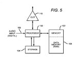
- FIG. 5 is a block diagram of a signal processing system which can suitably be used to execute the method of the invention in an embodiment using a general or special purpose, programmable microprocessor.
- the invention concerns processing of audio signals, either in digital or analog form.
- analog waveforms are often shown to illustrate the concepts; however, it should be understood that typical embodiments of the invention will operate in the context of a time series of digital bytes or words, said bytes or words forming a discrete approximation of an analog signal.
- the discrete, digital signal corresponds to a digital represention of a periodically sampled audio waveform.
- the waveform must be sampled at a rate at least sufficient to satisfy the Nyquist sampling theorem for the frequencies of interest.
- the quantization scheme and bit resolution should be chosen to satisfy the requirements of a particular application, according to principles well known in the art.
- the techniques and apparatus of the invention could be, and typically would be applied independently in a number of channels, for example in a two channel “stereo” system or in a “surround” audio system having more than two channels.
- a digital realization of the invention is the primary focus of the disclosure, the invention is not limited to a digital embodiment and could be realized in analog circuitry.
- FIGS. 1 a , 1 b , and 1 c show exemplary (continuous) waveforms as might be expected in a prior art method of bass enhancement by harmonic generation.
- FIG. 1 a shows a fundamental sinusoidal bass tone 10 .
- FIG. 1 b shows a harmonic-rich waveform 12 obtained by squaring the waveform of FIG. 1 a .
- the squared waveform 12 includes frequency components at 21 , where f is the frequency of the fundamental 10 .
- FIG. 1 c shows at 14 the sum of waveforms 10 and 12 . This waveform would be produced by prior art methods of bass enhancement by harmonic generation.
- the waveform 14 does include added harmonic content (in this case even harmonic at frequency 2 f ). However, it is also apparent from the peak levels 16 (positive) and 18 (negative) that the waveform 14 has had a peak offset introduced, and is no longer symmetrical about the zero level 20 . Specifically, in the example, for normalized waveform with amplitude A, the waveform 14 has been shifted by a unwanted d.c. bias so that the positive peak 16 reaches a much higher absolute value than the negative peak at 18 .
- bias or offset in waveform 14 has undesirable consequences in that more dynamic range or “headroom” must be preserved to prevent saturation, a situation in which the wave exceeds the maximum value that can be represented in the given quantization range.
- the offset will effectively reduce the usable range of values before saturation, effectively making the bit allocation less efficient. Scaling down the waveform would avoid saturation but increase quantization noise.
- the problem is particularly troublesome because the offset is not constant with amplitude, but instead varies with the root-mean-square (rms) value of the waveform. In the case of musical audio content, the rms value changes quickly and over a very large, unpredictable range. This makes it difficult to zero the waveform by simple subtraction of an offset. Frequent calculation of rms values would require a large number of calculations, requiring processing power and time. In many audio applications processing power and time are limited by the specification and cost considerations.
- the present invention provides a simple method to reduce or eliminate the offset introduced by harmonic generation.
- the method of the invention consumes few processor cycles, involves little computation and memory, introduces little delay and requires relatively small amounts of memory.
- FIG. 2 shows in procedural terms a generalized method in accordance with the invention.
- An audio signal is input in step 22 , suitably represented in time domain.
- a linear PCM representation could be used.
- the input audio is split and follows parallel paths through two branches of the algorithm.
- the input audio is filtered (step 24 ) either by a low pass or bandpass filter, to select a bass frequency range which is to be enhanced.
- the filtering step may extract a range of frequencies, for example from 0 to 200 Hz, for enhancement by harmonic generation.
- the frequency range from 0 to 120 Hz is selected.
- the upper cutoff frequency will depend upon the anticipated limitations of the bass reproduction in the assumed speaker system that is to be employed.
- Multi-tap digital filters such as a finite-impulse-response (FIR) filter could be used.
- the input audio could be presented in a frequency domain representation; which can be filtered by appropriate windowing in the frequency domain.
- the resulting frequency representation can thereafter be converted to time domain by an inverse transformation (such as an inverse FFT).
- the selected frequency range is processed by a method to generate harmonics.
- the waveform may be multiplied by itself (each sample squared) to generate “even” harmonics (at frequencies corresponding to the fundamental frequency multiplied by even integers).
- This method generates a strong harmonic at frequency 2 f , where f is the frequency of the selected fundamental tone.
- Higher ordered harmonics can be generated by cubing the signal or taking the waveform to higher (odd) powers to generate “odd” harmonics (at odd multiples of the fundamental frequency).
- the signal can be multiplied by a strongly non-linear function (such as an exponential function, analogous to a semiconductor diode junction).
- harmonics are generated to produce a harmonically enriched signal.
- step 27 the harmonically-enriched signal is filtered with a high pass or bandpass filter to attenuate the fundamental and remove D.C. components (if any, added during harmonic generation). Strong low-frequency fundamentals and D.C. components are found in some embodiments to interfere with faithful operation of a speaker system, particularly with low-cost, small speakers which are unable to cope with wide, low frequency excursions.
- step 27 Removal of D.C. components from even-numbered harmonics in step 27 is optional but desirable to reduce offset. Nevertheless, the removal of D.C. offset in step 27 (or 26 ) is not sufficient-without the other steps of the invention-to completely remove unwanted offset. This is because further offset is (in conventional methods) introduced in later mixing or summation steps. Furthermore, the offset introduced in said mixing steps is highly variable, depending on signal content. This makes removal by conventional means difficult.
- phase shift step 28
- the original input audio is shifted in phase (phase shift, step 28 ) preferably by an angle greater than zero degrees and less than 180 degrees (lead or lag).
- phase shift step 28
- our references to phase are measured in relation to the fundamental waveform (see FIG. 3 a ). It is found sufficient to choose an assumed fundamental frequency approximately at a centroid frequency in the bass region (for example, at 60 Hz for a Bass range defined from 0 to 120 Hz). It has been found most preferable to set the phase shift in this step 28 to approximately 90 degrees of phase. As explained below in connection with FIGS. 3 a - 3 c , this phase shift is most useful in decreasing or eliminating the offset introduced into the bass-enhanced waveform.
- phase shifting it is optionally desirable to filter the shifted signal with a high pass filter to attenuate fundamental components below a cutoff frequency which defines the limitations of the intended bass transducers.
- a high pass filter to attenuate fundamental components below a cutoff frequency which defines the limitations of the intended bass transducers.
- the presence of strong low-frequency signals or D.C. bias may interfere with the performance of low-cost, small speakers or audio transducers.
- Inclusion of high-pass filters in at least one of steps prevents the undue amplification of the fundamentals, which might otherwise occur.
- phase-shifted harmonic signal is added back to the original input audio signal (step 30 ).
- the phase-shifted harmonic signal might be scaled before adding it to the input audio signal, for greater control of the bass enhancement.
- the sum of the input audio with the phase-shifted harmonics is output (step 32 ), either to the speaker or for further processing before eventual reproduction.
- FIGS. 3 a , 3 b , and 3 c demonstrate the effect of the method of the invention on an exemplary sinusoidal waveform.
- FIG. 3 a shows the input audio waveform at 40 .
- FIG. 3 b shows a waveform 42 derived by squaring (self-multiplication) the input audio 40 , filtering to remove fundamental, then phase shifting. Note that the waveform 42 differs in phase from the counterpart waveform 12 in FIG. 1 b .
- FIG. 3 c shows at 44 the sum of waveforms 40 and 42 .
- the peak positive excursion 46 of waveform 44 is noticeably lower than the peak positive excursion of the corresponding waveform 14 in FIG. 1 a . This helps prevent the digital value from exceeding the maximum value permitted within the digital representation scheme (linear pcm, for example). Peak negative excursion at 47 is almost the same absolute value as the positive excursion; compared to the prior art method of FIGS. 1 a to 1 c , bias or offset has been reduced or eliminated.
- the invention may also include injection of odd harmonics (in step 26 ). Odd harmonics are less troublesome than even harmonics. The cubing of a waveform, for example, produces a wave generally symmetrical about zero, and thus does not tend to introduce offset. However, the phase shift introduced in step 28 above can also be applied to the odd harmonics without reducing the effectiveness. In addition, higher ordered even harmonics may be generated in step 26 . For example, fourth-order harmonics may be generated by raising the signal to the fourth power, and so forth.
- phase shift in step 28 is a relative shift, which introduces either lead or lag between the signal in the second branch and that in the first branch.
- the signal in the opposite branch could undergo phase shifting, to produce essentially the same result.
- the method of the invention includes introducing a relative phase difference between a signal in a first branch and another signal in a second branch.
- FIG. 4 shows in schematic form one embodiment of an apparatus in accordance with the invention.
- An audio signal is input to a first filter 50 which selects the bass region for enhancement.
- the 20 to 120 Hz frequency range is selected (frequencies below 20 Hz are generally assumed absent).
- the filtering may be performed by a specialized or programmable DSP integrated circuit, or by a programmable microprocessor and associated memory.
- the output of the first filter 50 is input to a harmonic generator 52 , which could be a programmable general or special purpose digital signal processing circuit. Harmonics may be generated numerically by the methods mentioned above, or by other known methods.
- the output of the harmonic generator 52 is then filtered by a second (high pass) filter 54 to attenuate the fundamental and remove any D.C. bias or offset. The result serves as a first input 56 into a summing circuit 61 .
- the original input signal also passes through a phase shift circuit in a parallel branch or signal path.
- the phase shifting circuit suitably can be realized by a general purpose programmable microprocessor or a specialized dsp processor of the type used to implement an FIR digital filter.
- the DSP processor chip “ADSP-21367”, available from Analog Devices, Inc. (ADI) could be programmed to introduce a suitable phase delay.
- the number of samples required to introduced a desired phase delay depends on the assumed fundamental frequency of the bass fundamental tone f 0 .
- the frequency can be approximated by an arbitrary frequency selected within the subband selected for enhancement, for example, the frequency situated mid-band in the subband.
- the center frequency is assumed at 80 Hz.
- frequencies from 20 to 120 Hz are selected for enhancement.
- the phase delay can be approximated by introducing a delay given by the equations given above, with an assumed center frequency at 80 Hz.
- the delay is suitably set to 90 degrees (pi/4) at 80 Hz.
- One extremely convenient method of introducing the delay is to store samples sequentially in a random access addressable memory. An memory offset number is then added or subtracted to the data address pointer, and the data retrieved is thereby delayed by a number of samples corresponding to the memory offset number.
- the audio signal data could be stored in a FIFO buffer or shift register with length corresponding to the desired delay.
- the phase-shifted signal is preferably filtered with a high pass filter 60 to attenuate fundamental and eliminate D.C. bias, then input into a second input 62 of the summation circuit 61 .
- the second input 62 of the summation circuit 61 thus receives a phase shifted and filtered version of the original audio signal.
- the summation circuit sums the harmonic-enriched signal with the phase shifted input audio signal to produce an output signal enriched with harmonics of bass tones in the selected bass subband.
- the enriched output signal is more easily reproduced by small speakers (such as headphones) to give a convincing psychoacoustic illusion of enhanced bass response.
- the summation circuit could also be realized by a programmable microprocessor suitably programmed to sum audio samples from input audio with the phase-shifted harmonic signal.
- This processor could be the same or a different processor working in parallel.
- the method of the present invention requires little calculation and is effective over a range of amplitudes to reduce offset which would otherwise be introduced (an unwanted artifact accompanying the even harmonics of the bass tone). It thus introduces very little delay and the reduction in offset allows the processor to take advantage of a full dynamic range without saturation or re-scaling the signal.
- FIG. 5 shows a block diagram of a signal processing system which can suitably be used to execute the method of the invention using a general or special purpose, programmable microprocessor.
- Microprocessor 100 communicates with program instructions stored in program memory 102 , which may be permanently written (firmware) or may be loaded from a mass storage device 104 . Appropriately buffered input audio samples are received at inputs 106 .
- the microprocessor acts under program control to perform the functions as described above in connection with FIG. 2 .
- Intermediate results and buffered data are written and read to/from data memory 108 , which may be random access memory.
- Sufficient memory to store at least sufficient samples to accommodate the required delay, plus sufficient memory for any multi-tap digital filters is required.
- Output signal is output in the form of a series of discrete digitized samples at output port 110 .
- Any suitable form of input and output interfaces may be employed, including SPDIF, HDMI, USB, “Firewire”, IIS bus, and other electrical or optical data interfaces.
- phase shifting such as the “Hilbert transform” could be substitutes for pure delay.
- signal phase is a relative concept. For this reason, it is possible to create numerous similar or functionally equivalent variant methods of introducing the phase shift: For example, where the above describes introducing a phase shift in a first “signal” branch of the signal path, equivalent results can be obtained by introducing a contrary phase shift in the “harmonic enriched” path. Similarly, phase shifts could be introduced in both paths in combination, to yield an algebraic sum of phase shifts.
- memory offset or shifts could be introduced by various means, including indirect addressing and by using an address offset vector.
- various delay lines could be employed including first-in, first out (FIFO) buffers, shift registers, or even analog delay lines such as charge coupled devices (CCD) or other analog memory devices.
- the signal could be transformed into a frequency domain representation (suitably by a discrete cosine transform). Frequency peaks in the bass region could then be pitch-shifted upward to harmonic frequencies, and the resulting signal inverse-transformed back into a time-domain representation for further processing. This method may be advantageous in some applications, but will generally require more processor power and memory allocation.
Landscapes
- Physics & Mathematics (AREA)
- Engineering & Computer Science (AREA)
- Acoustics & Sound (AREA)
- Signal Processing (AREA)
- Circuit For Audible Band Transducer (AREA)
- Tone Control, Compression And Expansion, Limiting Amplitude (AREA)
Abstract
Description
delay=(sampling rate)/(4×(center frequency)) Eq. 1:
where the delay is in seconds and frequency in Hz. This is easily generalized to calculate the delay for any arbitrary Tau.
Tau=2π*delay*sampling rate Eq. 2:
(for tau in radians, delay in seconds, sampling rate in Hz).
Claims (21)
Priority Applications (4)
| Application Number | Priority Date | Filing Date | Title |
|---|---|---|---|
| US12/001,184 US8005233B2 (en) | 2007-12-10 | 2007-12-10 | Bass enhancement for audio |
| CNA2008101306019A CN101459865A (en) | 2007-12-10 | 2008-06-25 | Bass enhancement for audio |
| PCT/US2008/013101 WO2009075726A1 (en) | 2007-12-10 | 2008-11-25 | Bass enhancement for audio |
| TW097145515A TW200944040A (en) | 2007-12-10 | 2008-11-25 | Bass enhancement for audio |
Applications Claiming Priority (1)
| Application Number | Priority Date | Filing Date | Title |
|---|---|---|---|
| US12/001,184 US8005233B2 (en) | 2007-12-10 | 2007-12-10 | Bass enhancement for audio |
Publications (2)
| Publication Number | Publication Date |
|---|---|
| US20090147963A1 US20090147963A1 (en) | 2009-06-11 |
| US8005233B2 true US8005233B2 (en) | 2011-08-23 |
Family
ID=40721697
Family Applications (1)
| Application Number | Title | Priority Date | Filing Date |
|---|---|---|---|
| US12/001,184 Expired - Fee Related US8005233B2 (en) | 2007-12-10 | 2007-12-10 | Bass enhancement for audio |
Country Status (4)
| Country | Link |
|---|---|
| US (1) | US8005233B2 (en) |
| CN (1) | CN101459865A (en) |
| TW (1) | TW200944040A (en) |
| WO (1) | WO2009075726A1 (en) |
Cited By (10)
| Publication number | Priority date | Publication date | Assignee | Title |
|---|---|---|---|---|
| US20080170719A1 (en) * | 2006-09-26 | 2008-07-17 | Sony Corporation | Signal processing apparatus |
| US20080170721A1 (en) * | 2007-01-12 | 2008-07-17 | Xiaobing Sun | Audio enhancement method and system |
| US20130163784A1 (en) * | 2011-12-27 | 2013-06-27 | Dts Llc | Bass enhancement system |
| US20140210536A1 (en) * | 2013-01-31 | 2014-07-31 | Aicatel-Lucent USA Inc. | Technique For Filtering Of Clock Signals |
| US9247342B2 (en) | 2013-05-14 | 2016-01-26 | James J. Croft, III | Loudspeaker enclosure system with signal processor for enhanced perception of low frequency output |
| US9319789B1 (en) * | 2008-02-26 | 2016-04-19 | Tc Group A/S | Bass enhancement |
| US10033443B2 (en) | 2016-04-15 | 2018-07-24 | Alcatel-Lucent Usa Inc. | MIMO transceiver suitable for a massive-MIMO system |
| US10218400B2 (en) | 2013-01-31 | 2019-02-26 | Nokia Of America Corporation | Technique for filtering of clock signals |
| US11477573B2 (en) | 2020-05-19 | 2022-10-18 | Asustek Computer Inc. | Handheld electronic device with multiple speakers |
| US20240098401A1 (en) * | 2022-09-09 | 2024-03-21 | Shenzhen Dancing Future Technology Ltd. | Suspended audio device with bass boost performance |
Families Citing this family (31)
| Publication number | Priority date | Publication date | Assignee | Title |
|---|---|---|---|---|
| US20060293089A1 (en) * | 2005-06-22 | 2006-12-28 | Magix Ag | System and method for automatic creation of digitally enhanced ringtones for cellphones |
| CN101771913B (en) * | 2009-09-28 | 2013-03-13 | 瑞声声学科技(深圳)有限公司 | Device for controlling bass sound reproduction of audio frequency signal and method |
| US8743364B2 (en) | 2009-12-02 | 2014-06-03 | Axalta Coating Systems Ip Co., Llc | Method and system for matching color and coarseness appearance of coatings |
| US8284957B2 (en) * | 2010-07-12 | 2012-10-09 | Creative Technology Ltd | Method and apparatus for stereo enhancement of an audio system |
| US8965546B2 (en) | 2010-07-26 | 2015-02-24 | Qualcomm Incorporated | Systems, methods, and apparatus for enhanced acoustic imaging |
| US20120033829A1 (en) * | 2010-08-04 | 2012-02-09 | Lewis Ivan Lawayne | Audio phase corrector |
| US8855322B2 (en) * | 2011-01-12 | 2014-10-07 | Qualcomm Incorporated | Loudness maximization with constrained loudspeaker excursion |
| US9055367B2 (en) * | 2011-04-08 | 2015-06-09 | Qualcomm Incorporated | Integrated psychoacoustic bass enhancement (PBE) for improved audio |
| JP2013038713A (en) | 2011-08-10 | 2013-02-21 | Semiconductor Components Industries Llc | Audio signal processing circuit |
| JP2013046242A (en) | 2011-08-24 | 2013-03-04 | Semiconductor Components Industries Llc | Sound signal processing circuit |
| US10448161B2 (en) | 2012-04-02 | 2019-10-15 | Qualcomm Incorporated | Systems, methods, apparatus, and computer-readable media for gestural manipulation of a sound field |
| SG11201407708YA (en) * | 2012-05-29 | 2014-12-30 | Creative Tech Ltd | Adaptive bass processing system |
| US20140006017A1 (en) | 2012-06-29 | 2014-01-02 | Qualcomm Incorporated | Systems, methods, apparatus, and computer-readable media for generating obfuscated speech signal |
| CN103369429B (en) * | 2013-06-17 | 2017-04-26 | 深圳Tcl新技术有限公司 | Low voice enhancing method and device and voice control device |
| JP6286925B2 (en) | 2013-08-19 | 2018-03-07 | ヤマハ株式会社 | Audio signal processing device |
| US9323879B2 (en) | 2014-02-07 | 2016-04-26 | Freescale Semiconductor, Inc. | Method of optimizing the design of an electronic device with respect to electromagnetic emissions based on frequency spreading introduced by hardware, computer program product for carrying out the method and associated article of manufacture |
| US9400861B2 (en) | 2014-02-07 | 2016-07-26 | Freescale Semiconductor, Inc. | Method of optimizing the design of an electronic device with respect to electromagnetic emissions based on frequency spreading introduced by software, computer program product for carrying out the method and associated article of manufacture |
| US9323878B2 (en) * | 2014-02-07 | 2016-04-26 | Freescale Semiconductor, Inc. | Method of optimizing the design of an electronic device with respect to electromagnetic emissions based on frequency spreading introduced by data post-processing, computer program product for carrying out the method and associated article of manufacture |
| US10893362B2 (en) | 2015-10-30 | 2021-01-12 | Guoguang Electric Company Limited | Addition of virtual bass |
| US10405094B2 (en) * | 2015-10-30 | 2019-09-03 | Guoguang Electric Company Limited | Addition of virtual bass |
| EP3171362B1 (en) * | 2015-11-19 | 2019-08-28 | Harman Becker Automotive Systems GmbH | Bass enhancement and separation of an audio signal into a harmonic and transient signal component |
| CN105764010B (en) * | 2016-05-05 | 2019-05-24 | 天津市计量监督检测科学研究院 | A kind of real-time overtone editor circuit |
| JP2018092012A (en) * | 2016-12-05 | 2018-06-14 | ソニー株式会社 | Information processing apparatus, information processing method, and program |
| EP3382703A1 (en) * | 2017-03-31 | 2018-10-03 | Fraunhofer-Gesellschaft zur Förderung der angewandten Forschung e.V. | Apparatus and methods for processing an audio signal |
| CN107959906B (en) * | 2017-11-20 | 2020-05-05 | 英业达科技有限公司 | Sound effect enhancing method and sound effect enhancing system |
| CN112997511B (en) * | 2018-11-16 | 2023-02-03 | 狄拉克研究公司 | Generating Harmonics in Audio Systems |
| KR102705131B1 (en) * | 2019-06-19 | 2024-09-10 | 삼성디스플레이 주식회사 | Display device |
| DE102019126509A1 (en) * | 2019-10-01 | 2021-04-01 | Harman Becker Automotive Systems Gmbh | IMPROVING THE SUBJECTIVE BASS PERCEPTION OF AN AUDIO SIGNAL WITH THE HELP OF HIGHER HARMONICS |
| US11218805B2 (en) * | 2019-11-01 | 2022-01-04 | Roku, Inc. | Managing low frequencies of an output signal |
| CN116074685A (en) * | 2021-10-29 | 2023-05-05 | 上海艾为电子技术股份有限公司 | A mobile device and its audio signal processing method and device |
| CN114495895B (en) * | 2021-12-22 | 2025-11-07 | 北京百度网讯科技有限公司 | Symmetrical audio acquisition method and device, electronic equipment and storage medium |
Citations (10)
| Publication number | Priority date | Publication date | Assignee | Title |
|---|---|---|---|---|
| US4150253A (en) | 1976-03-15 | 1979-04-17 | Inter-Technology Exchange Ltd. | Signal distortion circuit and method of use |
| US4984273A (en) | 1988-11-21 | 1991-01-08 | Bose Corporation | Enhancing bass |
| US5243658A (en) | 1990-08-10 | 1993-09-07 | Casio Computer Co., Ltd. | Modulation effect adding apparatus |
| US5744992A (en) | 1995-12-20 | 1998-04-28 | Vlsi Technology, Inc. | Digital phase shifter |
| US6134330A (en) | 1998-09-08 | 2000-10-17 | U.S. Philips Corporation | Ultra bass |
| US6285767B1 (en) | 1998-09-04 | 2001-09-04 | Srs Labs, Inc. | Low-frequency audio enhancement system |
| US6792119B1 (en) | 1997-05-05 | 2004-09-14 | Koninklijke Philips Electronics N.V. | Audio system |
| US6865430B1 (en) * | 1999-09-10 | 2005-03-08 | David W. Runton | Method and apparatus for the distribution and enhancement of digital compressed audio |
| US7031474B1 (en) | 1999-10-04 | 2006-04-18 | Srs Labs, Inc. | Acoustic correction apparatus |
| US20080103763A1 (en) * | 2006-10-27 | 2008-05-01 | Sony Corporation | Audio processing method and audio processing apparatus |
-
2007
- 2007-12-10 US US12/001,184 patent/US8005233B2/en not_active Expired - Fee Related
-
2008
- 2008-06-25 CN CNA2008101306019A patent/CN101459865A/en active Pending
- 2008-11-25 WO PCT/US2008/013101 patent/WO2009075726A1/en not_active Ceased
- 2008-11-25 TW TW097145515A patent/TW200944040A/en unknown
Patent Citations (10)
| Publication number | Priority date | Publication date | Assignee | Title |
|---|---|---|---|---|
| US4150253A (en) | 1976-03-15 | 1979-04-17 | Inter-Technology Exchange Ltd. | Signal distortion circuit and method of use |
| US4984273A (en) | 1988-11-21 | 1991-01-08 | Bose Corporation | Enhancing bass |
| US5243658A (en) | 1990-08-10 | 1993-09-07 | Casio Computer Co., Ltd. | Modulation effect adding apparatus |
| US5744992A (en) | 1995-12-20 | 1998-04-28 | Vlsi Technology, Inc. | Digital phase shifter |
| US6792119B1 (en) | 1997-05-05 | 2004-09-14 | Koninklijke Philips Electronics N.V. | Audio system |
| US6285767B1 (en) | 1998-09-04 | 2001-09-04 | Srs Labs, Inc. | Low-frequency audio enhancement system |
| US6134330A (en) | 1998-09-08 | 2000-10-17 | U.S. Philips Corporation | Ultra bass |
| US6865430B1 (en) * | 1999-09-10 | 2005-03-08 | David W. Runton | Method and apparatus for the distribution and enhancement of digital compressed audio |
| US7031474B1 (en) | 1999-10-04 | 2006-04-18 | Srs Labs, Inc. | Acoustic correction apparatus |
| US20080103763A1 (en) * | 2006-10-27 | 2008-05-01 | Sony Corporation | Audio processing method and audio processing apparatus |
Cited By (16)
| Publication number | Priority date | Publication date | Assignee | Title |
|---|---|---|---|---|
| US8094835B2 (en) * | 2006-09-26 | 2012-01-10 | Sony Corporation | Signal processing apparatus |
| US20080170719A1 (en) * | 2006-09-26 | 2008-07-17 | Sony Corporation | Signal processing apparatus |
| US20080170721A1 (en) * | 2007-01-12 | 2008-07-17 | Xiaobing Sun | Audio enhancement method and system |
| US8229135B2 (en) * | 2007-01-12 | 2012-07-24 | Sony Corporation | Audio enhancement method and system |
| US9319789B1 (en) * | 2008-02-26 | 2016-04-19 | Tc Group A/S | Bass enhancement |
| US20130163784A1 (en) * | 2011-12-27 | 2013-06-27 | Dts Llc | Bass enhancement system |
| US9236842B2 (en) * | 2011-12-27 | 2016-01-12 | Dts Llc | Bass enhancement system |
| US9712916B2 (en) | 2011-12-27 | 2017-07-18 | Dts Llc | Bass enhancement system |
| US20140210536A1 (en) * | 2013-01-31 | 2014-07-31 | Aicatel-Lucent USA Inc. | Technique For Filtering Of Clock Signals |
| US10218400B2 (en) | 2013-01-31 | 2019-02-26 | Nokia Of America Corporation | Technique for filtering of clock signals |
| US9247342B2 (en) | 2013-05-14 | 2016-01-26 | James J. Croft, III | Loudspeaker enclosure system with signal processor for enhanced perception of low frequency output |
| US10090819B2 (en) | 2013-05-14 | 2018-10-02 | James J. Croft, III | Signal processor for loudspeaker systems for enhanced perception of lower frequency output |
| US10033443B2 (en) | 2016-04-15 | 2018-07-24 | Alcatel-Lucent Usa Inc. | MIMO transceiver suitable for a massive-MIMO system |
| US11477573B2 (en) | 2020-05-19 | 2022-10-18 | Asustek Computer Inc. | Handheld electronic device with multiple speakers |
| US20240098401A1 (en) * | 2022-09-09 | 2024-03-21 | Shenzhen Dancing Future Technology Ltd. | Suspended audio device with bass boost performance |
| US12495242B2 (en) * | 2022-09-09 | 2025-12-09 | Shenzhen Dancing Future Technology Ltd. | Suspended audio device with bass boost performance |
Also Published As
| Publication number | Publication date |
|---|---|
| TW200944040A (en) | 2009-10-16 |
| US20090147963A1 (en) | 2009-06-11 |
| CN101459865A (en) | 2009-06-17 |
| WO2009075726A1 (en) | 2009-06-18 |
Similar Documents
| Publication | Publication Date | Title |
|---|---|---|
| US8005233B2 (en) | Bass enhancement for audio | |
| US8094835B2 (en) | Signal processing apparatus | |
| CN101166019B (en) | Audio signal processing device and method | |
| US9210506B1 (en) | FFT bin based signal limiting | |
| CN101241150B (en) | Apparatus, method for processing signal and method for generating signal | |
| US8077882B2 (en) | Audio reproducing apparatus | |
| CN101170302B (en) | Audio processing method and audio processing apparatus | |
| JP5098569B2 (en) | Bandwidth expansion playback device | |
| CN104937659B (en) | Car engine sound is extracted and is reproduced | |
| TWI765325B (en) | Subband spatial and crosstalk processing using spectrally orthogonal audio components | |
| JP3605363B2 (en) | Acoustic effect device, its method and program recording medium | |
| Bai et al. | Synthesis and implementation of virtual bass system with a phase-vocoder approach | |
| CN104704855A (en) | System and method for reducing latency in transposer-based virtual bass systems | |
| CN1538784B (en) | Audio signal processing device and method thereof | |
| KR101329308B1 (en) | Method for enhancing Bass of Audio signal and apparatus therefore, Method for calculating fundamental frequency of audio signal and apparatus therefor | |
| HK1130383A (en) | Bass enhancement for audio | |
| KR100684029B1 (en) | Method for generating harmonics using Fourier transform and apparatus therefor, method for generating harmonics by down sampling, apparatus for same and method for sound correction and apparatus for same | |
| JP2008219844A (en) | Highly-efficient low-pitched sound emphasizing technology | |
| CN115691522A (en) | Method, system, equipment and storage medium for enhancing bass | |
| Scheuing et al. | Frequency shifting for acoustic feedback reduction | |
| JP2000122700A (en) | Pitch shift apparatus and method | |
| JP2011151698A (en) | Source signal supplementation apparatus |
Legal Events
| Date | Code | Title | Description |
|---|---|---|---|
| AS | Assignment |
Owner name: DTS, INC., CALIFORNIA Free format text: ASSIGNMENT OF ASSIGNORS INTEREST;ASSIGNOR:SMITH, WILLIAM P.;REEL/FRAME:020273/0254 Effective date: 20071127 |
|
| AS | Assignment |
Owner name: DTS, INC., CALIFORNIA Free format text: ASSIGNMENT OF ASSIGNORS INTEREST;ASSIGNOR:SMITH, WILLIAM PAUL;REEL/FRAME:022227/0896 Effective date: 20071127 |
|
| STCF | Information on status: patent grant |
Free format text: PATENTED CASE |
|
| FPAY | Fee payment |
Year of fee payment: 4 |
|
| AS | Assignment |
Owner name: WELLS FARGO BANK, NATIONAL ASSOCIATION, AS ADMINIS Free format text: SECURITY INTEREST;ASSIGNOR:DTS, INC.;REEL/FRAME:037032/0109 Effective date: 20151001 |
|
| AS | Assignment |
Owner name: ROYAL BANK OF CANADA, AS COLLATERAL AGENT, CANADA Free format text: SECURITY INTEREST;ASSIGNORS:INVENSAS CORPORATION;TESSERA, INC.;TESSERA ADVANCED TECHNOLOGIES, INC.;AND OTHERS;REEL/FRAME:040797/0001 Effective date: 20161201 |
|
| AS | Assignment |
Owner name: DTS, INC., CALIFORNIA Free format text: RELEASE BY SECURED PARTY;ASSIGNOR:WELLS FARGO BANK, NATIONAL ASSOCIATION;REEL/FRAME:040821/0083 Effective date: 20161201 |
|
| FEPP | Fee payment procedure |
Free format text: MAINTENANCE FEE REMINDER MAILED (ORIGINAL EVENT CODE: REM.); ENTITY STATUS OF PATENT OWNER: LARGE ENTITY |
|
| LAPS | Lapse for failure to pay maintenance fees |
Free format text: PATENT EXPIRED FOR FAILURE TO PAY MAINTENANCE FEES (ORIGINAL EVENT CODE: EXP.); ENTITY STATUS OF PATENT OWNER: LARGE ENTITY |
|
| STCH | Information on status: patent discontinuation |
Free format text: PATENT EXPIRED DUE TO NONPAYMENT OF MAINTENANCE FEES UNDER 37 CFR 1.362 |
|
| FP | Lapsed due to failure to pay maintenance fee |
Effective date: 20190823 |
|
| AS | Assignment |
Owner name: INVENSAS CORPORATION, CALIFORNIA Free format text: RELEASE BY SECURED PARTY;ASSIGNOR:ROYAL BANK OF CANADA;REEL/FRAME:052920/0001 Effective date: 20200601 Owner name: TESSERA ADVANCED TECHNOLOGIES, INC, CALIFORNIA Free format text: RELEASE BY SECURED PARTY;ASSIGNOR:ROYAL BANK OF CANADA;REEL/FRAME:052920/0001 Effective date: 20200601 Owner name: FOTONATION CORPORATION (F/K/A DIGITALOPTICS CORPORATION AND F/K/A DIGITALOPTICS CORPORATION MEMS), CALIFORNIA Free format text: RELEASE BY SECURED PARTY;ASSIGNOR:ROYAL BANK OF CANADA;REEL/FRAME:052920/0001 Effective date: 20200601 Owner name: TESSERA, INC., CALIFORNIA Free format text: RELEASE BY SECURED PARTY;ASSIGNOR:ROYAL BANK OF CANADA;REEL/FRAME:052920/0001 Effective date: 20200601 Owner name: IBIQUITY DIGITAL CORPORATION, MARYLAND Free format text: RELEASE BY SECURED PARTY;ASSIGNOR:ROYAL BANK OF CANADA;REEL/FRAME:052920/0001 Effective date: 20200601 Owner name: DTS, INC., CALIFORNIA Free format text: RELEASE BY SECURED PARTY;ASSIGNOR:ROYAL BANK OF CANADA;REEL/FRAME:052920/0001 Effective date: 20200601 Owner name: DTS LLC, CALIFORNIA Free format text: RELEASE BY SECURED PARTY;ASSIGNOR:ROYAL BANK OF CANADA;REEL/FRAME:052920/0001 Effective date: 20200601 Owner name: PHORUS, INC., CALIFORNIA Free format text: RELEASE BY SECURED PARTY;ASSIGNOR:ROYAL BANK OF CANADA;REEL/FRAME:052920/0001 Effective date: 20200601 Owner name: INVENSAS BONDING TECHNOLOGIES, INC. (F/K/A ZIPTRONIX, INC.), CALIFORNIA Free format text: RELEASE BY SECURED PARTY;ASSIGNOR:ROYAL BANK OF CANADA;REEL/FRAME:052920/0001 Effective date: 20200601 |