US8001072B2 - Determining satisfiability of a function with arbitrary domain constraints - Google Patents
Determining satisfiability of a function with arbitrary domain constraints Download PDFInfo
- Publication number
- US8001072B2 US8001072B2 US12/141,923 US14192308A US8001072B2 US 8001072 B2 US8001072 B2 US 8001072B2 US 14192308 A US14192308 A US 14192308A US 8001072 B2 US8001072 B2 US 8001072B2
- Authority
- US
- United States
- Prior art keywords
- function
- variables
- computer
- decision diagram
- vertices
- Prior art date
- Legal status (The legal status is an assumption and is not a legal conclusion. Google has not performed a legal analysis and makes no representation as to the accuracy of the status listed.)
- Expired - Fee Related, expires
Links
Images


Classifications
-
- G—PHYSICS
- G06—COMPUTING OR CALCULATING; COUNTING
- G06N—COMPUTING ARRANGEMENTS BASED ON SPECIFIC COMPUTATIONAL MODELS
- G06N5/00—Computing arrangements using knowledge-based models
- G06N5/02—Knowledge representation; Symbolic representation
Definitions
- Boolean satisfiability problem can be generally stated as follows: for a given Boolean function of variables, determine whether it is possible to assign values to the variables such that the function is satisfied (that is, the function evaluates to true), or whether no such assignment exists.
- the Boolean satisfiability problem is of significance in both theoretical research and in practical applications such as artificial intelligence planning, circuit testing, software verification, and database validation.
- the satisfiability problem can be solved by representing the Boolean function as a directed acyclic graph (DAG), where each vertex of the DAG represents a variable assignment with the exception of two sink nodes.
- DAG directed acyclic graph
- One sink node represents false function results (e.g., binary zero) and the other sink node represents true function results (e.g., binary one).
- Each vertex of the DAG likewise has a binary domain.
- the function is satisfiable if there is a path through the DAG from a root node to the “one” sink (the true node).
- a decision diagram that has at least one vertex representing a domain of more than two values can be constructed.
- FIG. 1 illustrates a hierarchy of logical functions according to one embodiment.
- FIG. 2 is a block diagram of an example of a computer system upon which embodiments of a satisfiability solver may be implemented.
- FIG. 3 is a block diagram illustrating the transformation of a function into a decision diagram according to one embodiment.
- FIG. 4 is a flowchart of one embodiment of a computer-implemented method for determining satisfiability of a function.
- FIG. 5 illustrates an example of a decision diagram structure according to one embodiment.
- Embodiments described herein may be discussed in the general context of computer-executable instructions residing on some form of computer-usable medium, such as program modules, executed by one or more computers or other devices.
- program modules include routines, programs, objects, components, data structures, etc., that perform particular tasks or implement particular abstract data types.
- the functionality of the program modules may be combined or distributed as desired in various embodiments.
- a function can be represented as a canonical decision diagram structure.
- Each vertex of the diagram is associated with a respective function variable.
- the vertices include at least one vertex that represents a domain of more than two values for the variable associated with the vertex.
- the decision diagram demonstrates whether the function is valid, satisfiable or unsatisfiable.
- logical functions are represented using the hierarchy shown in FIG. 1 . All classes are immutable with the exception of the knowledge base class, which aggregates facts.
- a term “TermExpr” and a term “TreeExpr” are forms of the Boolean expression “BoolExpr.”
- the term “TermExpr” exposes in its “T_Identifier” property either a “DomainConstraint” or a “DomainVariable”—in the latter case, the term is treated as a Boolean variable with domain ⁇ true, false ⁇ .
- the terms “NotExpr,” “AndExpr” and “OrExpr” are forms of the term “TreeExpr.”
- FIG. 2 shows a block diagram of an example of a computer system 200 upon which the embodiments described herein may be implemented.
- the system 200 typically includes at least one processing unit 202 and memory 204 .
- the system 200 includes at least some form of computer-usable media.
- Computer-usable media can be any available media that can be accessed by the system 200 .
- the memory 204 may be volatile (such as random access memory), non-volatile (such as read-only memory, flash memory, etc.) or some combination of the two.
- This most basic configuration is illustrated in FIG. 2 by dashed line 206 .
- the system 200 may also have additional features/functionality.
- the system 200 may also include additional storage (removable and/or non-removable) including, but not limited to, magnetic or optical disks or tape. Such additional storage is illustrated in FIG. 2 by removable storage 208 and non-removable storage 210 .
- the system 200 may also contain communications connection(s) 212 that allow the device to communicate with other devices.
- the system 200 includes at least some form of computer-usable media.
- Computer-usable media can be any available media that can be accessed by the system 200 .
- Computer-usable media may comprise computer storage media and communication media.
- Computer storage media includes volatile and nonvolatile, removable and non-removable media implemented in any method or technology for storage of information such as computer-readable instructions, data structures, program modules or other data.
- Computer storage media includes, but is not limited to, random access memory (RAM), read only memory (ROM), electrically erasable programmable ROM (EEPROM), flash memory or other memory technology, compact disk ROM (CD-ROM), digital versatile disks (DVDs) or other optical storage, magnetic cassettes, magnetic tape, magnetic disk storage or other magnetic storage devices, or any other medium that can be used to store the desired information and that can accessed by the system 200 . Any such computer storage media may be part of the system 200 .
- the memory 204 , removable storage 208 and non-removable storage 210 are all examples of computer storage media.
- Communication media can embody computer-readable instructions, data structures, program modules or other data in a modulated data signal such as a carrier wave or other transport mechanism and includes any information delivery media.
- modulated data signal means a signal that has one or more of its characteristics set or changed in such a manner as to encode information in the signal.
- communication media includes wired media such as a wired network or direct-wired connection, and wireless media such as acoustic, radio frequency (RF), infrared and other wireless media. Combinations of any of the above can also be included within the scope of computer-readable media.
- the communications connection(s) 212 is an example of communication media.
- the system 200 may also have input device(s) 214 such as keyboard, mouse, pen, voice input device, touch input device, etc.
- Output device(s) 216 such as a display, speakers, printer, etc. may also be included. All these devices are well know in the art and need not be discussed at length here.
- the system 200 may operate in a networked environment using logical connections to one or more remote computers, which may be a personal compute (PC), a server, a router, a network PC, a peer device or other common network node, and which may include many or all of the elements described above relative to the system 200 .
- the logical connections may include a local area network (LAN) and a wide area network (WAN), but may also include other networks.
- LAN local area network
- WAN wide area network
- Such networking environments are commonplace in offices, enterprise-wide computer networks, intranets and the Internet.
- the system 200 can be connected to the network through the communication connection(s) 212 .
- the memory 204 includes computer-readable instructions, data structures, program modules and the like associated with a satisfiability solver application programming interface (API) 250 .
- the satisfiability solver API 250 may instead reside in any one of the computer storage media used by the system 200 , or may be distributed over some combination of the computer storage media.
- FIG. 3 provides an overview of the various stages in the transformation of a function according to one embodiment.
- the satisfiability solver API 250 decomposes a function 310 of ‘n’ arguments (variables) into a canonical decision diagram structure 330 such as a directed acyclic graph (DAG). If the decision diagram 330 resolves only to a false sink node, then no assignment of the variables can succeed. If the decision diagram resolves only to a true sink node, then all variable assignments are successful. If the decision diagram resolves to both a false sink node and a true sink node, then some variable assignments (the assignments that lead to the true sink) are successful.
- DAG directed acyclic graph
- the decision diagram 330 is canonical in the sense that all functionally equivalent definitions are represented in the same manner. More specifically, in one embodiment, the decision diagram 330 has the following properties:
- the satisfiability solver described herein improves efficiency by representing functions as decision diagrams in which variables have arbitrarily sized domains.
- domain constraints that are always true can be set to 1 while domain constraints that are always false can be set to 0, in which case variables with domains of size 0 or 1 are disqualified from consideration.
- Vertices in the decision diagram have the following structure:
- Vertex ⁇ ‘ variable identifier int Variable; ‘ vertices representing an outcome for each possible variable assignment ‘note: children are ordinally aligned with members of the variable domain Vertex[ ] Children; ⁇
- variable X can be replaced with a new variable X′ with the following discrete values:
- a normal form 340 (e.g., a disjunctive normal form and/or a conjunctive normal form) of the function 310 can be derived from the decision diagram 330 . This is discussed further below, in conjunction with FIG. 5 .
- FIG. 4 is a flowchart 400 of one embodiment of a computer-implemented method for determining satisfiability of a function.
- steps are exemplary. That is, various other steps or variations of the steps recited in the flowchart 400 can be performed. The steps in the flowchart 400 may be performed in an order different than presented.
- the features of the various embodiments described by the flowchart 400 can be used alone or in combination with each other.
- the flowchart 400 can be implemented as computer-executable instructions stored in a computer-readable medium.
- a function to be evaluated is accessed from memory.
- the function includes some number of arguments (variables), some or all of which may have a continuous domain.
- the function is represented in a different form (function 320 of FIG. 3 ) in which the variables have discrete domains, as previously described herein.
- the function 320 is transformed by mapping each of its expressions to a respective if-then-else statement.
- a mapping of expression to if-then-else form is shown in Table 1.
- each if-then-else statement is transformed into a vertex of the decision diagram 330 ( FIG. 3 ).
- the following recursive function is used to affect the transformation from if-then-else form to vertex:
- “EvaluateFor” evaluates a vertex for a particular value of the variable corresponding to that vertex. In essence, a vertex representing the function when the variable value is bound to the particular value is returned. “EvaluateFor” can be implemented as follows:
- each vertex is generated for each member of the variable domain, in contrast to conventional implementations that generate a fixed pair of children.
- Each vertex can be viewed as defining the Shannon decomposition of the function at the vertex on the vertex's variable.
- the resulting decision diagram is used to evaluate the function to determine whether the function is valid, satisfiable or unsatisfiable for given values of the variables.
- the decision diagram generated in block 440 is merely examined. All unsatisfiable functions resolve to 0 and all valid functions resolve to 1; otherwise, the function is satisfiable but not valid.
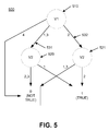
- FIG. 5 illustrates an example of a decision diagram structure 500 according to one embodiment.
- the structure 500 is generated as described above and satisfies each of the properties presented above in conjunction with FIG. 3 .
- the vertex 510 corresponds to the variable v 1
- the vertices 520 and 521 correspond to the variable v 2 .
- the outgoing edge 531 is associated with v 1 in the domain ⁇ 1 , 3 ⁇
- the outgoing edge 532 is associated with v 2 in the domain ⁇ 2 ⁇ .
- the edge 531 can be alternatively represented as two edges, one for the domain ⁇ 1 ⁇ and one for the domain ⁇ 3 ⁇ .
- the structure 500 can be used to evaluate the function ⁇ (v 1 , v 2 ) to determine whether the function is satisfiable or unsatisfiable for given values of the variables.
- the function is satisfiable for the following variable assignment: v 1 in ⁇ 1 , 3 ⁇ , v 2 in ⁇ 1 ⁇ ; and v 1 in ⁇ 2 ⁇ , v 2 in ⁇ 2 ⁇ .
- the normal form of the function can be derived from the decision diagram derived in block 440 of FIG. 4 .
- a disjunctive normal form can be read directly from the decision diagram, where every clause corresponds to a path from the root to the true node. In other words, every variable combination that results in the function being satisfied is a clause in the disjunctive normal form.
- FIG. 5 can be used to demonstrate the derivation of the disjunction normal form. As already mentioned, the following paths lead to the true node: v 1 in ⁇ 1 , 3 ⁇ , v 2 in ⁇ 1 ⁇ ; and v 1 in ⁇ 2 ⁇ , v 2 in ⁇ 2 ⁇ .
- the disjunctive normal form is therefore (v 1 in ⁇ 1 , 3 ⁇ AND v 2 in ⁇ 1 ⁇ ) OR (v 1 in ⁇ 2 ⁇ AND v 2 in ⁇ 2 ⁇ ).
- the conjunctive normal form can be readily derived as well by considering the disjunctive normal form of the negation of the function, or the set of all paths that lead to the false node: v 1 in ⁇ 1 , 3 ⁇ , v 2 in ⁇ 2 , 3 ⁇ ; v 1 in ⁇ 2 ⁇ , v 2 in ⁇ 1 , 3 ⁇ ; and v 1 in ⁇ 4 ⁇ , resulting in (v 1 in ⁇ 1 , 3 ⁇ AND v 2 in ⁇ 2 , 3 ⁇ ) OR (v 1 in ⁇ 2 ⁇ AND v 2 in ⁇ 1 , 3 ⁇ ) OR (v 1 in ⁇ 4 ⁇ ).
- the satisfiability solver described herein can efficiently determine whether any assignment to those variables will return true.
- the satisfiability solver can handle functions that can be represented in the following grammar:
Landscapes
- Engineering & Computer Science (AREA)
- Theoretical Computer Science (AREA)
- Computing Systems (AREA)
- Data Mining & Analysis (AREA)
- Evolutionary Computation (AREA)
- Physics & Mathematics (AREA)
- Computational Linguistics (AREA)
- General Engineering & Computer Science (AREA)
- General Physics & Mathematics (AREA)
- Mathematical Physics (AREA)
- Software Systems (AREA)
- Artificial Intelligence (AREA)
- Information Retrieval, Db Structures And Fs Structures Therefor (AREA)
Abstract
Description
-
- “domain” Di: a set of possible assignments for a variable vi; as will be seen, if the domain is continuous, it can be mapped to a discrete (finite) domain;
- “range” Ri: a set of valid assignments for a variable, Ri<Di;
- “domain constraint”: a function of the form “vi in Ri,” indicating that a value is constrained to take a value within a particular range;
- “expression”: an expression tree representing a logical function, and consisting of And, Or, Not and/or Domain Constraint nodes (vertices);
- “literal”: a domain constraint or its negation;
- “clause”: a conjunction or disjunction of literals;
- “sentence”: a conjunction or disjunction of clauses;
- “disjunctive normal form”: a logical function represented as a disjunction of conjunctive clauses;
- “conjunctive normal form”: a logical function represented as a conjunction of disjunctive clauses;
- “knowledge base”: an aggregation of facts, or true expressions;
- “satisfiable function”: a logical function that evaluates to true (e.g., a binary one) given some assignment of values to its input variables;
- “valid function”: a logical function that evaluates to true for every possible assignment to its input variables; and
- “invalid/unsatisfiable function”: a logical function that evaluates to false (e.g., a binary zero) for every possible assignment to its input variables.
-
- Each of its vertices represents a variable with the exception of two sink nodes (the false and true nodes). In the examples herein, the false node is assigned a value of binary zero (0) and the true node is assigned a value of binary one (1).
- Each outgoing edge for a particular vertex is labeled with a member of that vertex's domain (the domain of the variable associated with that vertex)—a vertex has an outgoing edge for each member of the vertex's domain.
- Each vertex is a function evaluated by choosing outgoing edges based on the assignment of the variable corresponding to the vertex.
- The variable identifier for the source of an outgoing edge is less than the variable identifier for the edge's target. In other words, the decision diagram 330 is ordered. The target may be one of the sink nodes. The order of the variables within the decision diagram 330 is arbitrary, although it is recognized that performance is sensitive to the choice of variable order. The ordering is consistently applied so that the decision diagram 330 is well-formed.
- The source of an outgoing edge cannot be a sink.
- The decision diagram 330 cannot contain two vertices that represent logically equivalent functions.
- A vertex may not exist where each outgoing edge targets the same vertex.
| Vertex | |
| { | |
| ‘ variable identifier | |
| int Variable; | |
| ‘ vertices representing an outcome for each possible variable | |
| assignment | |
| ‘note: children are ordinally aligned with members of the | |
| variable domain | |
| Vertex[ ] Children; | |
| } | |
X≧10 OR (X=5 AND X<7),
the variable X can be replaced with a new variable X′ with the following discrete values:
| X′ in {10, > 10}OR | (X ≧ 10) | ||
| ( | |||
| X′ in {5} AND | (X = 5) | ||
| X′ in {< 5, between 5 and 7} | (X < 7) | ||
| ) | |||
| TABLE 1 |
| Example Mapping of Expressions |
| Expression | If-Then-Else Form | ||
| x (term) | x-1-0 | ||
| x AND y | x-y-0 | ||
| x OR y | x-1-y | ||
| NOT x | x-0-1 | ||
| IfThenElse(vertex i, vertex t, vertex e) returns Vertex: |
| ‘ terminal |
| if i = 0 |
| return e |
| if i = 1 |
| return t |
| if t = 1 and e = 0 |
| return i |
| ‘ determine top variable from inputs (which roots the return expression) |
| top ← min(i.Variable, t.Variable, e.Variable) |
| ‘ compute children for new Vertex |
| Children[ ] ← Vertex[top domain size] |
| for each value in top domain |
| Children[value] ← IfThenElse( |
| EvaluateFor(i, top, value), |
| EvaluateFor(t, top, value), |
| EvaluateFor(e, top, value)) |
| ‘ if all children are identical, the value of top does not matter |
| if Children are identical |
| return Children[1] |
| return CreateVertex { .Variable = top, .Children = children } |
| EvaluateFor(Vertex v, int variable, int value) returns Vertex: |
| if v.Variable > variable |
| ‘ by order invariant, variable cannot influence v |
| return v |
| ‘ know that v.Variable must equal variable because top ≦ v.Variable |
| return v.Children[value] |
ƒ(v1,v2)=(v1 in {1,3} and v2 in {1}) or (v1 in {2} and v2 in {2}),
where v1 has domain {1,2,3,4} and v2 has domain {1,2,3}.
-
- Function: Relation Boolean;
- Relation: Variable=Constant|Variable>Constant|Variable≧Constant|Variable<Constant|Variable≦Constant|Variable≠Constant;
- Boolean: NOT(Function)|AND(Function,Function)|OR(Function,Function);
- Constant;
- Variable.
Claims (20)
Priority Applications (1)
| Application Number | Priority Date | Filing Date | Title |
|---|---|---|---|
| US12/141,923 US8001072B2 (en) | 2008-06-19 | 2008-06-19 | Determining satisfiability of a function with arbitrary domain constraints |
Applications Claiming Priority (1)
| Application Number | Priority Date | Filing Date | Title |
|---|---|---|---|
| US12/141,923 US8001072B2 (en) | 2008-06-19 | 2008-06-19 | Determining satisfiability of a function with arbitrary domain constraints |
Publications (2)
| Publication Number | Publication Date |
|---|---|
| US20090319461A1 US20090319461A1 (en) | 2009-12-24 |
| US8001072B2 true US8001072B2 (en) | 2011-08-16 |
Family
ID=41432257
Family Applications (1)
| Application Number | Title | Priority Date | Filing Date |
|---|---|---|---|
| US12/141,923 Expired - Fee Related US8001072B2 (en) | 2008-06-19 | 2008-06-19 | Determining satisfiability of a function with arbitrary domain constraints |
Country Status (1)
| Country | Link |
|---|---|
| US (1) | US8001072B2 (en) |
Cited By (1)
| Publication number | Priority date | Publication date | Assignee | Title |
|---|---|---|---|---|
| US9753484B1 (en) * | 2014-06-10 | 2017-09-05 | The United States Of America As Represented By The Director Of The National Security Agency | Satisfiability filter and query tool and method of building a satisfiability filter and query tool |
Families Citing this family (5)
| Publication number | Priority date | Publication date | Assignee | Title |
|---|---|---|---|---|
| US20130179378A1 (en) * | 2010-08-04 | 2013-07-11 | Sherwin Han | Knowledge Reasoning Method of Boolean Satisfiability (SAT) |
| WO2014152541A1 (en) | 2013-03-15 | 2014-09-25 | Sherwin Han | Spatial arithmetic method of sequence alignment |
| WO2014165752A1 (en) | 2013-04-04 | 2014-10-09 | Sherwin Han | A polynomial method of constructing a non-deterministic (np) turing machine |
| US9418137B2 (en) | 2014-08-29 | 2016-08-16 | Sherwin Han | Database without structured query language |
| EP3396564B1 (en) * | 2017-04-24 | 2021-08-04 | Nokia Solutions and Networks Oy | System state analysis |
Citations (14)
| Publication number | Priority date | Publication date | Assignee | Title |
|---|---|---|---|---|
| US5276897A (en) | 1989-06-16 | 1994-01-04 | Stalmarck Gunnar M N | System for determining propositional logic theorems by applying values and rules to triplets that are generated from boolean formula |
| US6714902B1 (en) | 2000-03-02 | 2004-03-30 | Cadence Design Systems, Inc. | Method and apparatus for critical and false path verification |
| US7120569B2 (en) | 2003-05-19 | 2006-10-10 | Javier Armando Arroyo-Figueroa | Sequential machine for solving boolean satisfiability (SAT) problems in linear time |
| US7216306B1 (en) | 1999-03-24 | 2007-05-08 | Zhe Li | Checkpoint restart method using condensed partial results by determining boolean constant subsets |
| US20070162966A1 (en) | 2006-01-12 | 2007-07-12 | International Business Machines Corporation | System and method for ratification of policies |
| US7506290B2 (en) * | 2005-09-13 | 2009-03-17 | International Business Machines Corporation | Method and system for case-splitting on nodes in a symbolic simulation framework |
| US7552407B2 (en) * | 2005-09-13 | 2009-06-23 | International Business Machines Corporation | Method and system for performing target enlargement in the presence of constraints |
| US7689943B2 (en) * | 2005-04-14 | 2010-03-30 | International Business Machines Corporation | Parametric reduction of sequential design |
| US7739635B2 (en) * | 2007-05-10 | 2010-06-15 | International Business Machines Corporation | Conjunctive BDD building and variable quantification using case-splitting |
| US7752593B2 (en) * | 2005-04-14 | 2010-07-06 | International Business Machines Corporation | Method for improved synthesis of binary decision diagrams with inverted edges and quantifiable as well as nonquantifiable variables |
| US7788616B2 (en) * | 2005-09-22 | 2010-08-31 | International Business Machines Corporation | Method and system for performing heuristic constraint simplification |
| US7882470B2 (en) * | 2005-04-14 | 2011-02-01 | International Business Machines Corporation | Method for heuristic preservation of critical inputs during sequential reparameterization |
| US7908575B2 (en) * | 2005-06-02 | 2011-03-15 | International Business Machines Corporation | Enhanced verification through binary decision diagram-based target decomposition using state analysis extraction |
| US7913205B2 (en) * | 2005-04-14 | 2011-03-22 | International Business Machines Corporation | Method and system for reversing the effects of sequential reparameterization on traces |
-
2008
- 2008-06-19 US US12/141,923 patent/US8001072B2/en not_active Expired - Fee Related
Patent Citations (18)
| Publication number | Priority date | Publication date | Assignee | Title |
|---|---|---|---|---|
| US5276897A (en) | 1989-06-16 | 1994-01-04 | Stalmarck Gunnar M N | System for determining propositional logic theorems by applying values and rules to triplets that are generated from boolean formula |
| US7216306B1 (en) | 1999-03-24 | 2007-05-08 | Zhe Li | Checkpoint restart method using condensed partial results by determining boolean constant subsets |
| US6714902B1 (en) | 2000-03-02 | 2004-03-30 | Cadence Design Systems, Inc. | Method and apparatus for critical and false path verification |
| US7120569B2 (en) | 2003-05-19 | 2006-10-10 | Javier Armando Arroyo-Figueroa | Sequential machine for solving boolean satisfiability (SAT) problems in linear time |
| US7765514B2 (en) * | 2005-04-14 | 2010-07-27 | International Business Machines Corporation | Method for improved synthesis of binary decision diagrams with inverted edges and quantifiable as well as nonquantifiable variables |
| US7913205B2 (en) * | 2005-04-14 | 2011-03-22 | International Business Machines Corporation | Method and system for reversing the effects of sequential reparameterization on traces |
| US7882470B2 (en) * | 2005-04-14 | 2011-02-01 | International Business Machines Corporation | Method for heuristic preservation of critical inputs during sequential reparameterization |
| US7689943B2 (en) * | 2005-04-14 | 2010-03-30 | International Business Machines Corporation | Parametric reduction of sequential design |
| US7917874B2 (en) * | 2005-04-14 | 2011-03-29 | International Business Machines Corporation | Reversing the effects of sequential reparameterization on traces |
| US7752593B2 (en) * | 2005-04-14 | 2010-07-06 | International Business Machines Corporation | Method for improved synthesis of binary decision diagrams with inverted edges and quantifiable as well as nonquantifiable variables |
| US7921394B2 (en) * | 2005-06-02 | 2011-04-05 | International Business Machines Corporation | Enhanced verification through binary decision diagram-based target decomposition |
| US7908575B2 (en) * | 2005-06-02 | 2011-03-15 | International Business Machines Corporation | Enhanced verification through binary decision diagram-based target decomposition using state analysis extraction |
| US7552407B2 (en) * | 2005-09-13 | 2009-06-23 | International Business Machines Corporation | Method and system for performing target enlargement in the presence of constraints |
| US7506290B2 (en) * | 2005-09-13 | 2009-03-17 | International Business Machines Corporation | Method and system for case-splitting on nodes in a symbolic simulation framework |
| US7788616B2 (en) * | 2005-09-22 | 2010-08-31 | International Business Machines Corporation | Method and system for performing heuristic constraint simplification |
| US7793242B2 (en) * | 2005-09-22 | 2010-09-07 | International Business Machines Corporation | Method and system for performing heuristic constraint simplification |
| US20070162966A1 (en) | 2006-01-12 | 2007-07-12 | International Business Machines Corporation | System and method for ratification of policies |
| US7739635B2 (en) * | 2007-05-10 | 2010-06-15 | International Business Machines Corporation | Conjunctive BDD building and variable quantification using case-splitting |
Non-Patent Citations (9)
| Title |
|---|
| Bryant Randal E. "Graph-Based Algorithms for Boolean Function Manipulation", Date: Aug. 1986, pp. 1-28, vol. C-35, Issue: 8. |
| Chelf Ben, "Satisfiability: A New Generation of Static Analysis", Date: 2007, 3 pages. |
| Decision Problems of Phrase-Structure Grammars, Landweber, Peter S.; Electronic Computers, IEEE Transactions on vol. EC-13 , Issue: 4 Digital Object Identifier: 10.1109/PGEC.1964.263815 Publication Year: 1964 , pp. 354-362. * |
| Fang, et al. "Complete Local Search for Propositional Satisfiability", Proceedings of the Nineteenth National Conference on Artificial Intelligence (AAAI2004), Date: Jul. 25-29, 2004, 6 pages, Copyright: 2004. |
| Kaser: a qualitatively fuzzy object-oriented inference engine, Rubin, S.H.; Rush, R.J., Jr.; Murthy, J.; Smith, M.H.; Trajkovic, L.; Fuzzy Information Processing Society, 2002. Proceedings. NAFIPS. 2002 Annual Meeting of the North American Digital Object Identifier: 10.1109/NAFIPS.2002.1018085 Publication Year: 2002 , pp. 354-359. * |
| Moskewickz, et al. "Chaff: Engineering an Efficient SAT Solver", Proceedings of the 38th conference on Design automation, Date: Jun. 18-22, 2001, pp. 530-535, ACM Press New York, NY, USA. |
| Routing Strategies to Enhance Traffic Capacity for Scale-Free Networks, Jianwei Wang; Lili Rong; Liang Zhang; Intelligent Computation Technology and Automation (ICICTA), 2008 International Conference on vol. 2 Digital Object Identifier: 10.1109/ICICTA.2008.103 Publication Year: 2008 , pp. 451-455. * |
| Silva, et al. "Grasp: A Search Algorithm for Propositional Satisfiability", Date: May 1999, pp. 506-521, vol. 48, Issue: 5. |
| Towards an Interpretable Sparseness for Face Recognition: An Empirical Study, Chao Lan; Xiao-yuan Jing; Qian Liu; Yongfang Yao; Jingyu Yang; Pattern Recognition (CCPR), 2010 Chinese Conference on Digital Object Identifier: 10.1109/CCPR.2010.5659245 Publication Year: 2010 , pp. 1-5. * |
Cited By (1)
| Publication number | Priority date | Publication date | Assignee | Title |
|---|---|---|---|---|
| US9753484B1 (en) * | 2014-06-10 | 2017-09-05 | The United States Of America As Represented By The Director Of The National Security Agency | Satisfiability filter and query tool and method of building a satisfiability filter and query tool |
Also Published As
| Publication number | Publication date |
|---|---|
| US20090319461A1 (en) | 2009-12-24 |
Similar Documents
| Publication | Publication Date | Title |
|---|---|---|
| Hébert-Johnson et al. | Multicalibration: Calibration for the (computationally-identifiable) masses | |
| Acampora et al. | A hybrid evolutionary approach for solving the ontology alignment problem | |
| Ben-Amram et al. | Ranking functions for linear-constraint loops | |
| US8001072B2 (en) | Determining satisfiability of a function with arbitrary domain constraints | |
| CN113238740B (en) | Code generation method, code generation device, storage medium and electronic device | |
| Ganji et al. | Having no mathematical model may not secure PUFs | |
| Zhang et al. | Constructing bent functions outside the Maiorana–McFarland class using a general form of Rothaus | |
| Campanelli et al. | Lookup arguments: Improvements, extensions and applications to zero-knowledge decision trees | |
| Hasan et al. | Graphettes: Constant-time determination of graphlet and orbit identity including (possibly disconnected) graphlets up to size 8 | |
| Zandron | Bounding the space in P systems with active membranes | |
| CN101662489B (en) | Method, device and system for discovering semantic Web service | |
| EP2921986B1 (en) | A system and method for evaluating a reverse query | |
| US8799754B2 (en) | Verification of data stream computations using third-party-supplied annotations | |
| Boche et al. | On effective convergence in Fekete’s lemma and related combinatorial problems in information theory | |
| Meel et al. | A faster FPRAS for# nfa | |
| Zenitani | A scalable algorithm for network reachability analysis with cyclic attack graphs | |
| Mangal et al. | Scaling relational inference using proofs and refutations | |
| Chistopolskaya et al. | On the Decision Tree Complexity of Threshold Functions | |
| Kejriwal | On using centrality to understand importance of entities in the Panama Papers | |
| Ebrahimzadeh et al. | On longest paths and diameter in random Apollonian networks | |
| Takimoto et al. | Predicting nearly as well as the best pruning of a decision tree through dynamic programming scheme | |
| Bagnall et al. | A library for algorithmic game theory in Ssreflect/Coq | |
| Mann | Simulating quantum computations with Tutte polynomials | |
| Feldman et al. | Learning coverage functions | |
| US20220230249A1 (en) | Condition tree optimization |
Legal Events
| Date | Code | Title | Description |
|---|---|---|---|
| AS | Assignment |
Owner name: MICROSOFT CORPORATION, WASHINGTON Free format text: ASSIGNMENT OF ASSIGNORS INTEREST;ASSIGNOR:MEEK, COLIN;REEL/FRAME:021433/0305 Effective date: 20080617 |
|
| ZAAA | Notice of allowance and fees due |
Free format text: ORIGINAL CODE: NOA |
|
| ZAAB | Notice of allowance mailed |
Free format text: ORIGINAL CODE: MN/=. |
|
| STCF | Information on status: patent grant |
Free format text: PATENTED CASE |
|
| AS | Assignment |
Owner name: MICROSOFT TECHNOLOGY LICENSING, LLC, WASHINGTON Free format text: ASSIGNMENT OF ASSIGNORS INTEREST;ASSIGNOR:MICROSOFT CORPORATION;REEL/FRAME:034564/0001 Effective date: 20141014 |
|
| FPAY | Fee payment |
Year of fee payment: 4 |
|
| MAFP | Maintenance fee payment |
Free format text: PAYMENT OF MAINTENANCE FEE, 8TH YEAR, LARGE ENTITY (ORIGINAL EVENT CODE: M1552); ENTITY STATUS OF PATENT OWNER: LARGE ENTITY Year of fee payment: 8 |
|
| FEPP | Fee payment procedure |
Free format text: MAINTENANCE FEE REMINDER MAILED (ORIGINAL EVENT CODE: REM.); ENTITY STATUS OF PATENT OWNER: LARGE ENTITY |
|
| LAPS | Lapse for failure to pay maintenance fees |
Free format text: PATENT EXPIRED FOR FAILURE TO PAY MAINTENANCE FEES (ORIGINAL EVENT CODE: EXP.); ENTITY STATUS OF PATENT OWNER: LARGE ENTITY |
|
| STCH | Information on status: patent discontinuation |
Free format text: PATENT EXPIRED DUE TO NONPAYMENT OF MAINTENANCE FEES UNDER 37 CFR 1.362 |
|
| FP | Lapsed due to failure to pay maintenance fee |
Effective date: 20230816 |