US800100A - Pleasure-railway. - Google Patents
Pleasure-railway. Download PDFInfo
- Publication number
- US800100A US800100A US25046405A US1905250464A US800100A US 800100 A US800100 A US 800100A US 25046405 A US25046405 A US 25046405A US 1905250464 A US1905250464 A US 1905250464A US 800100 A US800100 A US 800100A
- Authority
- US
- United States
- Prior art keywords
- vehicle
- screen
- car
- picture
- wheels
- Prior art date
- Legal status (The legal status is an assumption and is not a legal conclusion. Google has not performed a legal analysis and makes no representation as to the accuracy of the status listed.)
- Expired - Lifetime
Links
- 238000010276 construction Methods 0.000 description 3
- 230000000694 effects Effects 0.000 description 2
- 239000002184 metal Substances 0.000 description 2
- 230000003467 diminishing effect Effects 0.000 description 1
- 230000000284 resting effect Effects 0.000 description 1
- 239000011435 rock Substances 0.000 description 1
Images


Classifications
-
- A—HUMAN NECESSITIES
- A63—SPORTS; GAMES; AMUSEMENTS
- A63G—MERRY-GO-ROUNDS; SWINGS; ROCKING-HORSES; CHUTES; SWITCHBACKS; SIMILAR DEVICES FOR PUBLIC AMUSEMENT
- A63G7/00—Up-and-down hill tracks; Switchbacks
Definitions
- My invention relates to improvements in It has for its object to construct an" illusion amusement device in which a person can be made to feel that he is traveling and seeing the sights of some forcrossings, in combination with means to throw a moving picture upon a screen in front of the car.
- the invention also contemplates the creation of an artificial air-blast to be directed in the faces of the occupants of the vehicle to add to i the deception.
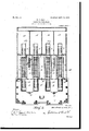
- Figure 1 is a front elevation of a building in which four of my vehicles are installed, part being broken away and showing twoof the tunnels or passages in section onthe line 00 w of Fig. 2.
- Fig. 2 is a general floor plan of the building.
- Fig. 3 is a longitudinal sec: tional view taken on the line y y of Fig. 2 through one of the tunnels and-showing the positions of the traveling car and the feeder, as well as the arrangement of the picture-machine and screen.
- Fig. 4 is an enlarged broken side View of the lower part of the traveling car, showing the way it is mounted.
- Fig. 5 isabroken vertical cross-sectional View showing the mechanism for rocking the car from side to side.
- Fig. 6 is a plan view be:
- Fig. 7 is a broken longitudinal section view showing the levers for operating the device adapted to engage with the lug-carrying chain to give the impression of going over crossings.
- the traveling car because the passengers thereof are made to feel that they are traveling.
- the movable car or feeder is run back and forth until the traveling car has been filled. The journey then begins.
- the front of the car is open and the passengers look out directly upon a screen arranged at the endof a dark room or compartment of thebuilding into whichthe front part of the car projects...
- Moving pictures taken along a railroad are thrown upon the screen, which is of such size and so arranged as to take up the whole field of vision.
- the traveling car is hinged at its longitudical center upon a stationary framework, "under which are arranged rollers resting upon other rollers carried by cross-shafts driven by a suitable motor.
- Said shafts also carry an endless belt provided with projecting lugs arranged at intervals on its surface. Said lugs come in contact with the upper end of an upstanding flexible metal piece secured to The sound of the I v a fixture before the car. lugs on the belt striking said metal standard resembles that of the wheels of a car pass- :to the porch 1.
- said flanged plate is raised into contact with the lugs on the belt, it sounds like a train passing over a crossing, and this device is therefore used to great advantage where cossings appear in the picture.
- the bottom of the car is connected to the supporting-framework also by levers, which are arranged in reach of the operator and by means of which he may tilt the car as a turn appears in the moving picture, thereby giving a very realistic effect.
- a fan or blower is provided and its blast directed in the faces of the occupants of the car.
- the floor of the car is preferably arranged on an incline to give all the passengers a good view.
- the exit from the building is preferably separate from the entrance and passes around the side of the tunnel.
- 1 designates the porch of the building; 2, the entrance-lobby, which is reached by the turnstile 3. Said entrance-lobbies are preferably arranged, as shown, between the outer ends of each pair of tracks 4, which pass through the tunnels 5 to the rear platforms 6 of the traveling cars 7.
- the exitpassages 8 are arranged at the sides of the tunnels, the passengers passing directly from the rear platform 6 of the car 7 through said passage and through a turnstile 8, if desired,
- a common exit passage may be provided between the two middle tunnels, and the spaces between the outer and inner tunnels are occupied by the attendants rooms 9, from which lead the stairs 10 to the lantern-gallery 11, arranged above the level of the cars 7 and slightly rearward thereof in order to get the requisite distance to project the pictures upon the screens 12 and at the same time have said screens close enough to the front of the cars so that they will cover the entire field of vision of the occupants thereof.
- Each screen is arranged at the end of one of the dark rooms 13, into which the front ends of the cars7project.
- the feedercars which run through the tunnels 5, are designated 14.
- VVhileI have provided the lantern-gallery in front of the screens and mount the picture-machine 15 therein, said picture-mac]line may be mounted behind the screen and throw the pictures through the screen, if desired, without departing from the spirit or sacrificing the advantages of my invention.
- the car 7 is mounted upon the stationary platform 16, to which it. is attached by the hinges 17 and upon which it may be turned toward one side or the other by means of the hand-lever 18, extending up through the floor 19 of the car, said lever being pivoted to the platform at 20 and carryinganother lever 21. fastened to the floor of the car. By throwing the lever to one side or the other the car is tilted in the same direction.
- the wheels below the platform are designated 22, and 23 represents the wheels arranged between them and mounted on the cross-shafts 21, carrying the intermediate pulleys 25, upon which runs the endless belt 26, having the projecting lugs 27.
- the driving engine or motor 28 is connected to the first cross-shaft by belt 22), running over the pulley 30 on said shaft, and the other shafts are driven by the lug-carrying beltit.
- the upstanding piece bl adapted to engage the lugs on the belt 26 to give the sound of passing over rail-joints. is preferably arranged between the two rear shafts, while the other upstanding rod 32, carrying the flanged plate 33, is arranged between the two front shafts and is connected by the rod 34;, pivoted at 35, to the hand-lever 36, extending up through the car-floor in reach of the operator.
- the fan or blower 37 is preferably arranged below the front platform 38 of the car, and its blast passes through the upwardly-extending passage 39 and is directed in the faces of the passengers in the car.
Landscapes
- Toys (AREA)
Description
No. 800,100. PATENTED SEPT. 19, 1905 G. 0. HALE. PLEASURE RAILWAY.
APPLICATION FILED MAB..14. 1905.
3 SHEET$-SHEET l.
avwantoz GEORGE CHALE No. 000,100. PATENTED SEPT. 19, 1905.
0. 0. HALE. PLEASURE RAILWAY.
APPLICATION FILED MAR-,14.l905
3 SHEETS-SHEET 2.
' Sawowkoz 2. r GEO/P65 c.// Wi t mam 6mm; x
No. 000,100. PATBNTED SEPT. 10, 1000.
Q 0 v 0. 0. HALE I PLEASURE RAILWAY.
APPLICATION FILED MAILM. 1905.
3 SHEETS-SHEET 3.
"UNITED srA- rns GEORGE O. HALF, .OF KANSAS CITY, MISSOURI, ASSIGNOR OF ONE-HALF PATENT oFFIoE.
TO FRED W. GIFFORD, OF KANSAS GITICMISSOURI.
\J PLEASURE-RAILWAY.
Specification of Letters Patent. i
Patented Sept. 19, mos.
Application filed. March I4, 1905. Serial No. 250,464.
To all whom, it may concern.-
Be it known that I, GEORGE C. HALE, a citizen of the United States, residing atK-ansas City, in the county of Jackson and State of Missouri, have invented certain new and useful Improvements in Pleasure-Railways; and
I do hereby declare the following to be a full,
clear, and exact description of the invention,
amusement devices.
such as will enable others skilled in the art to which it appertains to make and use the same.
My invention relates to improvements in It has for its object to construct an" illusion amusement device in which a person can be made to feel that he is traveling and seeing the sights of some forcrossings, in combination with means to throw a moving picture upon a screen in front of the car. v
The invention also contemplates the creation of an artificial air-blast to be directed in the faces of the occupants of the vehicle to add to i the deception.
The invention also consists in the details of construction and combinations of parts hereinafter described, and more particularly pointed out in the claims.
, In the accompanying drawings, illustrating the preferred embodiment of my invention, Figure 1 is a front elevation of a building in which four of my vehicles are installed, part being broken away and showing twoof the tunnels or passages in section onthe line 00 w of Fig. 2. Fig. 2 is a general floor plan of the building. Fig. 3 is a longitudinal sec: tional view taken on the line y y of Fig. 2 through one of the tunnels and-showing the positions of the traveling car and the feeder, as well as the arrangement of the picture-machine and screen. Fig. 4: is an enlarged broken side View of the lower part of the traveling car, showing the way it is mounted. Fig. 5isabroken vertical cross-sectional View showing the mechanism for rocking the car from side to side. Fig. 6 is a plan view be:
low the car, showing the arrangement of rollers and shafts; and Fig. 7 is a broken longitudinal section view showing the levers for operating the device adapted to engage with the lug-carrying chain to give the impression of going over crossings.
VV'hile the preferred embodiment of my invention is illustrated in the accompanying drawings and its construction and operation are described in this specification, the right is reserved to make such changes from the construction shown and described herein as the scope of the claims hereto appended will permit.
In carrying out my invention I construct a housing or building for my device which may -be adapted to receive several of the devices,
the traveling car, because the passengers thereof are made to feel that they are traveling. The movable car or feeder is run back and forth until the traveling car has been filled. The journey then begins. The front of the car is open and the passengers look out directly upon a screen arranged at the endof a dark room or compartment of thebuilding into whichthe front part of the car projects...
Moving pictures taken along a railroad are thrown upon the screen, which is of such size and so arranged as to take up the whole field of vision. i
The traveling car is hinged at its longitudical center upon a stationary framework, "under which are arranged rollers resting upon other rollers carried by cross-shafts driven by a suitable motor. Said shafts also carry an endless belt provided with projecting lugs arranged at intervals on its surface. Said lugs come in contact with the upper end of an upstanding flexible metal piece secured to The sound of the I v a fixture before the car. lugs on the belt striking said metal standard resembles that of the wheels of a car pass- :to the porch 1.
ing over the joints of the rail of a track, and the interval between the lugs on the belt and the speed of said belt may be varied at will, so that the passengers may be given the impression of moving at any rate of speed desirable. Thus the gradually-increasing speed of a starting train and its diminishing speed as it enters a stopping-place may be realistically reproduced. The revolving wheels below the framework give just enough sound and jar within the car as the wheels of a moving car usually do. Another upright provided with a flanged plate on its upper end is adapted to be raised into engagement with the lug-carrying belt by lever mechanism extending to the rear part of the car, where it may be controlled by the lecturer or guide. WVhen said flanged plate is raised into contact with the lugs on the belt, it sounds like a train passing over a crossing, and this device is therefore used to great advantage where cossings appear in the picture. The bottom of the car is connected to the supporting-framework also by levers, which are arranged in reach of the operator and by means of which he may tilt the car as a turn appears in the moving picture, thereby giving a very realistic effect. To further add to the completeness of the illusion, a fan or blower is provided and its blast directed in the faces of the occupants of the car. The floor of the car is preferably arranged on an incline to give all the passengers a good view. The exit from the building is preferably separate from the entrance and passes around the side of the tunnel.
Referring more particularly to the drawings, 1 designates the porch of the building; 2, the entrance-lobby, which is reached by the turnstile 3. Said entrance-lobbies are preferably arranged, as shown, between the outer ends of each pair of tracks 4, which pass through the tunnels 5 to the rear platforms 6 of the traveling cars 7. The exitpassages 8 are arranged at the sides of the tunnels, the passengers passing directly from the rear platform 6 of the car 7 through said passage and through a turnstile 8, if desired, A common exit passage may be provided between the two middle tunnels, and the spaces between the outer and inner tunnels are occupied by the attendants rooms 9, from which lead the stairs 10 to the lantern-gallery 11, arranged above the level of the cars 7 and slightly rearward thereof in order to get the requisite distance to project the pictures upon the screens 12 and at the same time have said screens close enough to the front of the cars so that they will cover the entire field of vision of the occupants thereof. Each screen is arranged at the end of one of the dark rooms 13, into which the front ends of the cars7project. .The feedercars, which run through the tunnels 5, are designated 14. VVhileI have provided the lantern-gallery in front of the screens and mount the picture-machine 15 therein, said picture-mac]line may be mounted behind the screen and throw the pictures through the screen, if desired, without departing from the spirit or sacrificing the advantages of my invention.
The car 7 is mounted upon the stationary platform 16, to which it. is attached by the hinges 17 and upon which it may be turned toward one side or the other by means of the hand-lever 18, extending up through the floor 19 of the car, said lever being pivoted to the platform at 20 and carryinganother lever 21. fastened to the floor of the car. By throwing the lever to one side or the other the car is tilted in the same direction. The wheels below the platform are designated 22, and 23 represents the wheels arranged between them and mounted on the cross-shafts 21, carrying the intermediate pulleys 25, upon which runs the endless belt 26, having the projecting lugs 27. The driving engine or motor 28 is connected to the first cross-shaft by belt 22), running over the pulley 30 on said shaft, and the other shafts are driven by the lug-carrying beltit. The upstanding piece bl, adapted to engage the lugs on the belt 26 to give the sound of passing over rail-joints. is preferably arranged between the two rear shafts, while the other upstanding rod 32, carrying the flanged plate 33, is arranged between the two front shafts and is connected by the rod 34;, pivoted at 35, to the hand-lever 36, extending up through the car-floor in reach of the operator. The fan or blower 37 is preferably arranged below the front platform 38 of the car, and its blast passes through the upwardly-extending passage 39 and is directed in the faces of the passengers in the car.
It has been found by actual operation of this amusement device that the illusion is ex tremely realistic, some of the passengers having been known to clutch the arms of their seats in fright at the apparent great speed of the car and the way it swung over to the side as it took the curves.
Having thus described my invention, what I claim as new, and desire to secure by Letters Patent, is-
1. The combination with a vehicle mounted on a stationary platform, said vehicle having its sides and rear end closed, and means to cause said platform to vibrate to give the inipression of moven'ient, of a screen exteauling across the field of vision from the vehicle and a picture-machine adapted to throw a moving picture on said screen.
2. The combination with a vehicle mounted on a stationary platform and means to create a sound like the wheels of a car going over the rail-joints of a track, of a screen extending across the field of vision from the vehicle and a picture-machine adapted to throw amoving picture on said screen.
3. The combination with a vehicle mounted on a stationary platform and means tocreate a sound like the wheels of a car passing over the railroad-crossings, of a screen extending across the field of vision from the vehicle and a picture-machine adapted to throw a moving picture on said screen. i i
4:. The combination with avehicle mounted on a stationary platform and means to-blow a blast of air into the faces of the occupants for the purpose specified, of a screen extenda ing across the field of vision from the vehicle and a picture-machine adapted to throw a moving picture on said screen.
5. The combination with a vehicle located in the dark, created by natural or artificial means,
and mounted on a stationary platform, said field of vision from the vehicle anda picturemachine adapted to throw a moving picture on said screen.
7. The combination with a vehicle located in a dark room and mounted on a stationary platform, said vehicle having its sides and rear end closed, wheels arranged on said platform and means to revolve saidwheels whereby the platform is caused to vibrate to give the impression of movement, ofa screen extending across the field of vision from the. vehicle and a picture-machine adapted to throw a moving picture on said screen.
8. The combination with a vehicle located in a dark room and mounted on a stationary plat form, said vehicle having its sides and rear end closed, wheels arranged on said platform, other wheels arranged between the wheels on said platform and adapted to engage said latter wheels and cause them to revolve-for the purpose specified, and means to revolve said second-mentioned wheels, of a screen extending across the field of vision from the vehicle I and a picture-machine adapted to throw a moving'picture on said screen.
9. The combination with a vehicle located in a dark room and mounted on a stationary platform, .wheels arranged on said platform, other wheels mounted on cross-shafts and adapted to engage the firstmentioned wheels and cause them to revolve for the purpose specified, means to revolve said shafts and means carried by said shafts for creating a sound like the wheels of a car going over the rail-joints of a track, of a screen extending across the field of vision from the vehicle and a picture: machine adapted to throw amoving picture on said screen. 1
10. The combination with a vehicle located in'a dark room and mounted on a stationary platform, wheels arranged on said platform, other wheels mounted on cross-shafts and adapted to engage the first-mentioned wheels and cause them to revolve'for the purpose specified, means to revolve said shafts, a belt carrying. lugs, mounted in said shaft, and a piece extending within the path of said lugs for the purpose specified, of a screen extending across the field of vision from-the vehicle and a picture-machine adapted to throw a moving picture on said screen.
11. The combination with a vehicle located in a dark room and mounted on a stationary platform, wheels arranged on said platform, other wheels mounted on cross shafts and adapted to engage the first-mentioned wheels and cause them to revolve for the purpose specified, means torevolve said shafts, a belt, carrying-lugs, mounted on said shaft, anda plate adapted to be brought into the path of said lugs for the purpose specified.
12. The combination with a vehicle located in a dark room and mounted on a stationary platform, wheels arranged on said platform, other wheels mounted on cross shafts and adapted to engage the first-mentioned wheels and cause them to revolvefor the purpose specified, means to revolve said shafts, a belt, carrying-lugs, mounted in said shaft, a plate adapted to be brought into the path of said lugs for the purpose specified, and means for operating said plate extending in reach of the operator, of a screen extending across the fieldof vision from the vehicle and a picturemachine adapted to throw a moving picture on'said screen. a 1
13. The combination with a vehicle located ina dark room and mounted on a stationary platform, and meanstorock said vehicle on said platform, of a screen extending across the field of vision from the vehicle and a picturemachine adapted to. throw a moving picture on said screen.
14:. The combination with a vehicle located in a dark room and mounted on a stationary platform, and means to rock said vehicleon said platform extending within reach of the operator, of a screen extending across the field of visionfrom the vehicle and a picture-machine adapted to throw a moving picture on said screen.
' 15. The combination with a vehicle located in a dark room and hinged near its longitudinal center to a stationary platform, and means to turn the vehicle on the hinge, of a screen extending acrossthe field of vision and a picture-machine adapted to throw a moving picture on said screen. r
16. The combination with a vehicle located in a dark room and connected to a stationary platform bymeans of a'central hinge, said vehicle adapted to tilt sidewise on said platform, and a series of levers terminating within ITO the vehicle, for tilting said vehicle, of a screen extending across the field of vision from the vehicle and a picture-machine adapted to throw a moving picture on said screen.
17. The combination with a vehicle located in a dark room and mounted upon a stationary platform, said vehicle having its sides and rear end closed, of means to cause said platform to vibrate for the purpose specified, a screen extending across the field of vision and a picture-machine adapted to throw a moving picture on said screen, and another vehicle adapted to bring passengers from without to said first-mentioned vehicle.
18. The combination with a vehicle located in a dark room and mounted upon a stationary platform, of means to cause said platform to vibrate for the purpose specified, a screen extending across the field of vision and a picture-machine adapted to throw a moving picture on said screen, a dark passage extending from without to said dark room, and another car adapted to run in said passage and bring the passengers to said first-mentioned vehicle.
19. The combination with a vehicle mounted on a stationary platform and located with its front portion extending into a dark room and the rear extending into a dark passage, another vehicle adapted to run through said passage to bring passengers to the first-mentioned vehicle, an exit-passage from the rear end of said first-mentioned vehicle without said passage, a screen extending across the field of vision and a picture-machine adapted to throw a moving picture on said screen.
' 20. The combination withavehiclemounted on a stationary platform and located with its front portion extending into a dark room and the rear portion extending into a dark passage, another vehicle adapted to run through said passage to bring passengers to the firstmentioned vehicle, an exit-passage, a screen extending across the field of vision for the vehicle in the dark room, and a picture-inachine, arranged in a gallery above the passage, adapted to throw a moving picture on said screen.
21. The combination with a vehicle open at one end and located in a dark place on a suitable frame, and means to cause said vehicle to vibrate and oscillate to give the effect to the occupants of said vehicle of riding toward the opening, of a screen arranged in front of the open end of the vehicle and covering the entire view through said open end, and a pietnre-machine arranged to throw a inovii'lg picture upon said screen.
22. The combination with a vehicle open at one end and located in a dark place, a supporting-frame for said vehicle, upper and lower sets of wheels on said frame, other wheels mounted on cross-shafts and arranged between, and adapted to engage, said firstmentioned wheels and cause them to revolve, for the purpose specified, and means to revolve said shafts, of a screen arranged in front of the open end of the vehicle and covering the entire view through said open end, and a picture-machine arranged to throw a moving picture upon said screen.
In testimony whereof I aflix my signature in presence of two witnesses.
GEORGE C. HALE.
Witnesses:
FRED W. GIFFORD, PHILIP LA TOMETA.
Priority Applications (1)
| Application Number | Priority Date | Filing Date | Title |
|---|---|---|---|
| US25046405A US800100A (en) | 1905-03-14 | 1905-03-14 | Pleasure-railway. |
Applications Claiming Priority (1)
| Application Number | Priority Date | Filing Date | Title |
|---|---|---|---|
| US25046405A US800100A (en) | 1905-03-14 | 1905-03-14 | Pleasure-railway. |
Publications (1)
| Publication Number | Publication Date |
|---|---|
| US800100A true US800100A (en) | 1905-09-19 |
Family
ID=2868586
Family Applications (1)
| Application Number | Title | Priority Date | Filing Date |
|---|---|---|---|
| US25046405A Expired - Lifetime US800100A (en) | 1905-03-14 | 1905-03-14 | Pleasure-railway. |
Country Status (1)
| Country | Link |
|---|---|
| US (1) | US800100A (en) |
-
1905
- 1905-03-14 US US25046405A patent/US800100A/en not_active Expired - Lifetime
Similar Documents
| Publication | Publication Date | Title |
|---|---|---|
| JP5683064B2 (en) | Amusement park rides | |
| US1713793A (en) | Amusement ride | |
| US2655116A (en) | Tilting track amusement apparatus | |
| US800100A (en) | Pleasure-railway. | |
| US965768A (en) | Amusement apparatus. | |
| US1890137A (en) | Amusement railway | |
| US872627A (en) | Amusement device. | |
| US788886A (en) | Device for illusory entertainment. | |
| US1354436A (en) | Amusement apparatus | |
| US845524A (en) | Pleasure-railway. | |
| US786117A (en) | Observation-train. | |
| US793471A (en) | Amusement device. | |
| US1508905A (en) | Amusement device | |
| US847725A (en) | Illusion apparatus. | |
| US590783A (en) | Amusement apparatus | |
| US946200A (en) | Amusement apparatus. | |
| US1564952A (en) | Rotary amusement device | |
| US778325A (en) | Amusement device. | |
| US887803A (en) | Amusement apparatus. | |
| US847724A (en) | Illusion device. | |
| US767281A (en) | Amusement device. | |
| US852184A (en) | Pleasure-railway. | |
| JPH0683095U (en) | Entertainment vehicle | |
| US1099952A (en) | Amusement apparatus. | |
| US643996A (en) | Pleasure-railway. |