US798029A - Driving mechanism for paper-making machines. - Google Patents
Driving mechanism for paper-making machines. Download PDFInfo
- Publication number
- US798029A US798029A US21645404A US1904216454A US798029A US 798029 A US798029 A US 798029A US 21645404 A US21645404 A US 21645404A US 1904216454 A US1904216454 A US 1904216454A US 798029 A US798029 A US 798029A
- Authority
- US
- United States
- Prior art keywords
- shaft
- paper
- belt
- driving mechanism
- pulleys
- Prior art date
- Legal status (The legal status is an assumption and is not a legal conclusion. Google has not performed a legal analysis and makes no representation as to the accuracy of the status listed.)
- Expired - Lifetime
Links
Images


Classifications
-
- F—MECHANICAL ENGINEERING; LIGHTING; HEATING; WEAPONS; BLASTING
- F16—ENGINEERING ELEMENTS AND UNITS; GENERAL MEASURES FOR PRODUCING AND MAINTAINING EFFECTIVE FUNCTIONING OF MACHINES OR INSTALLATIONS; THERMAL INSULATION IN GENERAL
- F16H—GEARING
- F16H9/00—Gearings for conveying rotary motion with variable gear ratio, or for reversing rotary motion, by endless flexible members
- F16H9/02—Gearings for conveying rotary motion with variable gear ratio, or for reversing rotary motion, by endless flexible members without members having orbital motion
- F16H9/04—Gearings for conveying rotary motion with variable gear ratio, or for reversing rotary motion, by endless flexible members without members having orbital motion using belts, V-belts, or ropes
- F16H9/08—Gearings for conveying rotary motion with variable gear ratio, or for reversing rotary motion, by endless flexible members without members having orbital motion using belts, V-belts, or ropes engaging a conical drum
Definitions
- Paper-Making Machines of which the following is a specification.
- This invention relates to driving mechanism for paper-making machines; and it consists in the novel features of construction and relative arrangement of parts hereinafter fully described in the specification, clearly illustrated in the drawings, and particularly pointed out in the claims.
- Figure 1 in side elevation, shows diagrammatically the arrangement of the several units comprising a paper-making machine.
- Fig. 2 in top plan view, shows diagrammatically such a machine equipped with my improved driving mechanism.
- Fig. 5 is a top plan view of the parts shown in Fig. 4.
- Fig. 6 is a view similar to Fig.4, showing a modified arrangement of the belt and pulleys comprising the driving mechanism.
- Fig. 7 is a top plan view 'of the parts shown in Fig. 6.
- Fig. 8 is a detail view similar to Fig. 6, showing the common form of driving unit now in use.
- Fig. 9 is a top plan view of the mechanism shown in Fig. 8.
- Fig. 1 represents the floor supporting the machine, the latter consisting of the wire mesh 2, the couch 3, the first press 4, second press 5, (sometimes a third press is used,) drier 6, a calender 7, the reels 8, the slitter 9, and winder 10.
- each of these units except the slitter 10 is provided with .an independent driving-shaft 11, each connected up to the main driving-shaft 12, so that each of the several units may be driven at a speed which must be adjustable suitable to its work independent of the speed at which the main Shaft or the other unit or units may be driven. I-Ieretofore these units have been connected to the main driving-shaft 12 by the arrangement shown in Figs.
- 13 represents a cone driving-pulley on the shaft 12.
- 14 represents a cone driven pulley on a counter-shaft 15, the two pulleys 13 and 14 being connected by a belt 16 in the usual Way for the purpose of driving the pulley 14 at different speeds.
- a bevel-gear 17 on the end of the counter-shaft 15 meshes with abevel-gear 18 and shaft 11.
- gears cause much vibration, which requires an exceedingly massive floor construction to withstand its effects, and the teeth are sometimes stripped by the sudden impact or stress applied to them by the throwing in of the clutch.
- driving unit is used that requires less power, less expensive construction of floors, is noiseless in operation and avoids the infirmity of the gears, lessens the cost of'repairs, increases the ef fective running time, and produces a steady, smooth, and uniform action, which makes a higher speed of the machine practicable, thus largely increasing its output.
- 20 represents a pulley fast on the end of the shaft 11.
- 21 represents a complemental pulley on the shaft 15, corresponding to the bevel-gears 17 and 18.
- a belt .22 connects the two pulleys 20 and 21, and as the shafts of the latter are arranged at right angles to each other I employ idle pulleys 23 24, over which the belt 22 passes from the pulley 20 to the pulley 21, thus connecting the two pulleys together and driving one by the other, although the axes of the two pulleys are at right angles to each other.
- I may use the idle pulleys 23 24 25, (shown in Fig.
- a driving mechanism for paper-making machines comprising a main driving-shaft for supplying power to the several groups of mechanism which compose the machine, a sep arate counter-shaft for each group, a speedvarying counter-shaft for each group countershaft, an independent belt connecting a member on each speed-varying counter-shaft with a complemental member on the main drivingshaft, and an independent belt connecting a member on each speed-varying counter-shaft with a complemental member on its complemental group counter-shaft.
- a driving mechanism for paper-making machines comprising a main driving-shaft for supplying power to the several groups of mechanism which compose the machine, a separate counter-shaft for each group, a speedvarying counter-shaft for each group countershaft, connections between each speed-varying counter-shaft and the main shaft, a pulley on each group counter-shaft, a complemental pulley on each speed-varying counter-shaft, said pulleys being arranged at an angle to each other, an intermediate pulley arranged at an angle to each of the said first-mentioned pulleys, and a belt connecting said pulleys, the surfaces of the said pulleys being so positioned with relation to each other that the center line of the belt will correspond to the intersections of the center planes of the two contiguous pulleys between which the belt is passing.
Description
PATENTED AUG. 22, 1905.
H. S. FERGUSON.
DRIVING MECHANISM FOR. PAPER. MAKING MACHINES.
APPLICATION FILED JULY 13, 1904.
3 SHEETS-SHEET 1.
vlfa
'lunlw. llv an! an new mutual-mum wnmamm a c,
PATENTED AUG. 22, 1905.
H. s. FERGUSON. DRIVING MECHANISM FOR PAPER MAKING MACHINES.
APPLICATION FILED JULY 13, 1904.
3 SHEETS-SHEET 2.
No. 798,029. PATENTED AUG. 22, 1905 i H. S. FERGUSON.
DRIVING MECHANISM FOR PAPER MAKING MACHINES.
APPLICATION FILED JULY 13, 1904.
s sums-sum s.
HARDY S. FERGUSON, BANGOR, MAINE.
DRIVING MECHANISM FOR PAPER-MAKING MACHINES.
Specification of Letters Patent.
Patented Aug. 22, 1905.
Application filed July 13, 1904:- Serial No. 216,454.
To all whom, it may concern-.-
Be it known thatI, HARDY S. FERGUSON, of Bangor, in the county of Penobscot and State of Maine, have invented certain new and use ful Improvements in Driving Mechanism for.
Paper-Making Machines, of which the following is a specification.
This invention relates to driving mechanism for paper-making machines; and it consists in the novel features of construction and relative arrangement of parts hereinafter fully described in the specification, clearly illustrated in the drawings, and particularly pointed out in the claims.
Figure 1, in side elevation, shows diagrammatically the arrangement of the several units comprising a paper-making machine. Fig. 2, in top plan view, shows diagrammatically such a machine equipped with my improved driving mechanism. Fig. 3, in side elevation, shows my improved driving mechanism applied to the several units of the machine. Fig. 4, in side elevation, shows one of the driving units shown in Fig. 3, the parts being illustrated on a somewhat larger scale. Fig. 5 is a top plan view of the parts shown in Fig. 4. Fig. 6 is a view similar to Fig.4, showing a modified arrangement of the belt and pulleys comprising the driving mechanism. Fig. 7 is a top plan view 'of the parts shown in Fig. 6. Fig. 8 is a detail view similar to Fig. 6, showing the common form of driving unit now in use. Fig. 9 is a top plan view of the mechanism shown in Fig. 8.
The same figures of reference indicate the same parts in all of the figures.
The several parts of the paper-making machine are shown in diagram, since they form no part of my present invention.
Referring to Fig. 1, 1 represents the floor supporting the machine, the latter consisting of the wire mesh 2, the couch 3, the first press 4, second press 5, (sometimes a third press is used,) drier 6, a calender 7, the reels 8, the slitter 9, and winder 10. As shown in Fig. 2, each of these units except the slitter 10 is provided with .an independent driving-shaft 11, each connected up to the main driving-shaft 12, so that each of the several units may be driven at a speed which must be adjustable suitable to its work independent of the speed at which the main Shaft or the other unit or units may be driven. I-Ieretofore these units have been connected to the main driving-shaft 12 by the arrangement shown in Figs. 8 and 9, wherein 13 represents a cone driving-pulley on the shaft 12. 14 represents a cone driven pulley on a counter-shaft 15, the two pulleys 13 and 14 being connected by a belt 16 in the usual Way for the purpose of driving the pulley 14 at different speeds. A bevel-gear 17 on the end of the counter-shaft 15 meshes with abevel-gear 18 and shaft 11. Although the infirmities of this form of driving mechanism have been well known for a long time, no way has been provided prior to my invention for avoiding the use of these bevel-gears 17 and 18. Such use prior to myinvention has been considered necessary in these large papermaking machines in order to maintain the relative speeds of the various units when they have been properly adjusted to provide for the stretch or shrinkage of the paper, which occurs at different stages of its progress over the machine. This form of mechanism causes considerable loss of power, is noisy, the gears requiring slushing of grease that is spattered about the room by centrifugal force unless casings are employed. There is always more or less wear and backlash, causing a jerky action of the units and producing uneven work, frequent breaks in the continuous sheet of paper, and attendant stops and loss of production. The gears cause much vibration, which requires an exceedingly massive floor construction to withstand its effects, and the teeth are sometimes stripped by the sudden impact or stress applied to them by the throwing in of the clutch. By my invention these gears are dispensed with and the driving unit is used that requires less power, less expensive construction of floors, is noiseless in operation and avoids the infirmity of the gears, lessens the cost of'repairs, increases the ef fective running time, and produces a steady, smooth, and uniform action, which makes a higher speed of the machine practicable, thus largely increasing its output.
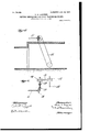
Referring to Figs. 4 and 5, 20 represents a pulley fast on the end of the shaft 11. 21 represents a complemental pulley on the shaft 15, corresponding to the bevel-gears 17 and 18. A belt .22 connects the two pulleys 20 and 21, and as the shafts of the latter are arranged at right angles to each other I employ idle pulleys 23 24, over which the belt 22 passes from the pulley 20 to the pulley 21, thus connecting the two pulleys together and driving one by the other, although the axes of the two pulleys are at right angles to each other. In place of the idle pulleys 23 24, as shown'in Fig.4, I may use the idle pulleys 23 24 25, (shown in Fig. 6,) the purpose being in eaclrcase to so deflect the belt 22 that it will properly engage the pulleys 2O 21. In place of the belt 1 may employ a rope or several ropes or other equivalent device. The elasticity of the belt avoids the difiiculties noted upon the starting of the machine where gears are employed and provides an efiicient and economical means for transmitting motion to the several units of the machine.
While in the claims I make use of the word belt, I do not wish to .be understood as thereby limiting my claims or the scope of my invention to a belt. I may and intend to use any equivalent device-such as a rope, &c.andI desire that where the word belt is used in the claim it is to be understood to be used in its generic sense and to comprise not only a belt strictly, but also a rope or analogous devices.
Referring to drawings, and particularly to Fig. 7, wherein 'is illustrated my improved mechanism for connecting the speed-varying means with its complemental unit by means of pulleys and a belt, it will be seen that the pulleys 2O 21 and also the intermediate pul leyssuch'as 23 24, &c.are arranged at such an angle with each other that the position of the center line of the belt corresponds to the intersection of the center planes of the two.
contiguous pulleys between which the belt is passing. By this arrangement I cannot only transmit power by means of a belt from pulley 21 to pulley 20, said pulleys being arranged at right angles to each other, but I also prevent the belt from running off the pulleys.
Having thus explained the nature of my invention and described a way of constructing and using the same, though without attemptto set forth all of the forms in which it is made or all the modes of its use, what I claim, and desire to secure by Letters Patent, is
1. A driving mechanism for paper-making machines, comprisinga main driving-shaft for supplying power to the several groups of mechanism which compose the machine, a sep arate counter-shaft for each group, a speedvarying counter-shaft for each group countershaft, an independent belt connecting a member on each speed-varying counter-shaft with a complemental member on the main drivingshaft, and an independent belt connecting a member on each speed-varying counter-shaft with a complemental member on its complemental group counter-shaft.
2. A driving mechanism for paper-making machines, comprising a main driving-shaft for supplying power to the several groups of mechanism which compose the machine, a separate counter-shaft for each group, a speedvarying counter-shaft for each group countershaft, connections between each speed-varying counter-shaft and the main shaft, a pulley on each group counter-shaft, a complemental pulley on each speed-varying counter-shaft, said pulleys being arranged at an angle to each other, an intermediate pulley arranged at an angle to each of the said first-mentioned pulleys, and a belt connecting said pulleys, the surfaces of the said pulleys being so positioned with relation to each other that the center line of the belt will correspond to the intersections of the center planes of the two contiguous pulleys between which the belt is passing.
In testimony whereof I have afiixed my signature in presence of two witnesses.
HARDY S. FERGUSON. l/Vitnesses:
J. V. TowER, F. O. BOWLER.
Priority Applications (1)
| Application Number | Priority Date | Filing Date | Title |
|---|---|---|---|
| US21645404A US798029A (en) | 1904-07-13 | 1904-07-13 | Driving mechanism for paper-making machines. |
Applications Claiming Priority (1)
| Application Number | Priority Date | Filing Date | Title |
|---|---|---|---|
| US21645404A US798029A (en) | 1904-07-13 | 1904-07-13 | Driving mechanism for paper-making machines. |
Publications (1)
| Publication Number | Publication Date |
|---|---|
| US798029A true US798029A (en) | 1905-08-22 |
Family
ID=2866518
Family Applications (1)
| Application Number | Title | Priority Date | Filing Date |
|---|---|---|---|
| US21645404A Expired - Lifetime US798029A (en) | 1904-07-13 | 1904-07-13 | Driving mechanism for paper-making machines. |
Country Status (1)
| Country | Link |
|---|---|
| US (1) | US798029A (en) |
-
1904
- 1904-07-13 US US21645404A patent/US798029A/en not_active Expired - Lifetime
Similar Documents
| Publication | Publication Date | Title |
|---|---|---|
| US798029A (en) | Driving mechanism for paper-making machines. | |
| US204969A (en) | Improvement in horse-powers | |
| US301380A (en) | malt by | |
| US154342A (en) | Improvement in machines for covering piano-strings | |
| US429331A (en) | Expansion-gear for rolls | |
| US812888A (en) | Speed-changing mechanism. | |
| US904582A (en) | Paper-making-machine drive. | |
| US297702A (en) | Machinery for making paper | |
| US923212A (en) | Variable-speed gear. | |
| US137352A (en) | Improvement in expanding pulleys | |
| US1081799A (en) | Friction-gearing. | |
| US790875A (en) | Hoisting and power-transmitting machine. | |
| US546060A (en) | Christian | |
| US275056A (en) | Paper-making machinery | |
| US812703A (en) | Belt-gearing for extractors. | |
| US359294A (en) | Paper-calendering machine | |
| US980435A (en) | Belt-drive. | |
| US548913A (en) | George h | |
| US361544A (en) | Half to thomas lewis | |
| US863990A (en) | Fan attachment for sewing-machines. | |
| US821814A (en) | Twisting-machine. | |
| US758768A (en) | Reversing-gear and clutch mechanism. | |
| US1080357A (en) | Drop-hammer mechanism. | |
| US1119759A (en) | Wire-netting machine. | |
| US588071A (en) | George b |