US797347A - Carousel. - Google Patents
Carousel. Download PDFInfo
- Publication number
- US797347A US797347A US22989004A US1904229890A US797347A US 797347 A US797347 A US 797347A US 22989004 A US22989004 A US 22989004A US 1904229890 A US1904229890 A US 1904229890A US 797347 A US797347 A US 797347A
- Authority
- US
- United States
- Prior art keywords
- platform
- spindle
- sleeve
- spaced
- platforms
- Prior art date
- Legal status (The legal status is an assumption and is not a legal conclusion. Google has not performed a legal analysis and makes no representation as to the accuracy of the status listed.)
- Expired - Lifetime
Links
- 241001465754 Metazoa Species 0.000 description 4
- NJPPVKZQTLUDBO-UHFFFAOYSA-N novaluron Chemical compound C1=C(Cl)C(OC(F)(F)C(OC(F)(F)F)F)=CC=C1NC(=O)NC(=O)C1=C(F)C=CC=C1F NJPPVKZQTLUDBO-UHFFFAOYSA-N 0.000 description 1
- 230000000153 supplemental effect Effects 0.000 description 1
Images
Classifications
-
- A—HUMAN NECESSITIES
- A63—SPORTS; GAMES; AMUSEMENTS
- A63G—MERRY-GO-ROUNDS; SWINGS; ROCKING-HORSES; CHUTES; SWITCHBACKS; SIMILAR DEVICES FOR PUBLIC AMUSEMENT
- A63G1/00—Roundabouts
- A63G1/06—Roundabouts with several concentric turntables
Definitions
- AROSBL AHPLIGATION mm1 0017.25. 1904.-.
- My inren tion relates to carousels or merrygorounds, and in carrying ont the same I employ a base, a spindle, revoluble platforms spaced apart and secured together one above the other, devices pivotally mounted in the lower platform passing throug'h the upper platform and upon which are mounted the forms of animals, carriages, or other devices on or in which passengers are carried, means for revolving the platforms, and means actuated by the revolution of the platforms to impart a swinging movement to the said devices, all of which will be hereinafter more particularly described.
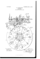
- Figure l is a plan view of the operating mechanism of my improved carousel.
- Fig. Q is a central sectional elevation on line w a
- Fig'. 1 is an elevation of the swinging' bar and the disk, gear, and connecting-rod by which the same is operated.
- a represents a base on which is placed a suitable pedestal a', in which a spindle Z) is secured.
- c represents a platform centrally through which the spindle Z) passes, and c' is alsoa platform provided with a central opening', and the platforms c and c' are preferably circular and secured together, the one above the other, in a spaced-apart relation by straps 2 or other suitable means.
- a bevel-gear 3 immediately below and secured to the platform c is a bevel-gear 3, surrounding the spindle
- a bevel-gear 4L, meshing with the gear 3 and secured to a shaft 5, journaled in bearings 6, is employed to impart a revoluble movement to the said platforms.
- a sleeve Z is secured on the spindle and intermediate of the lower end of the sleeve CZ and the platform c I prefer to employ a frame surrounding' the spindle t and comprising plates f j, secured together in any desired manner and spaced apart by an intervening ring l7, and a gear-wheel c surrounds the spindle Z) and is secured to the lower end of the sleeve (Z, and journaled at spaced-apart intervals in the circumference of a circle and in the platesff are a number of short shafts 3.
- Each of these short shafts 3 extends through the platef and is provided above the same with a gear-wheel la, meshing' with the gear-wheel e, and a disk lZ, provided at a point adjacent toits periphery with a pin 9, surrounded by a sleeve l0, on which at diametrically opposite points suitable lugs are provided.
- At equally-spaced-apart intervals adjacent to the periphery of the platform c ll employ a series of pairs of brackets l1, in each pair of which is mounted a yoke Z, the number of yokes Z corresponding' with the number of disks a, g'ear-wheels la, and 'short shafts 8.
- each yoke Z Secured to each yoke Z and extending from the same and through a slot c2 in the platform c is a bar l2, provided adjacent to the yoke with a sleeve 13, having' suitable lugs at diametrieally opposite points, and on the u pper end of each of the bars l2 is mounted the form of an animal, carriage, or other device on or in which a passenger may ride.
- 'llhe lugs on the sleeves l() and 13, respectively, are connected by rods fm., at whose ends are yokes spanning the sleeves and pivotally con- ⁇ nected to the lugs, and l also prefer to employ a stationary and supplemental platform n, which, as illustrated, may rest on and be carried by a shoulder' formed in the sleeve (Z, andthe platform fa is of suicient diameter to cover the opening in the platform c.
- each bar l2 passes freely througli an opening' in its slide-plate, and the slide-plate operates in guideways 1G, placed upon the platform cl adjacent and parallel to the slots c2, or the slide-plates may be otherwise arranged as found convenient.
- the amount of the swing imparted to the bars l2 will depend not only upon the size of the disks vf and the distance from the center that the pins 9 are mounted therein, but also upon the distance above the pivotal points of the yokes Z that the outer end of the connecting-rods m are pivotally connected to the rods l2.
- a carousel the combination with a base. and spindle, of a revoluble support, yoltes pivotally mounted thereon in spaced-apart positions, bars extending from said yolies, passenger-carrying devices mounted upon said bars and means actuated by the turning of said support for imparting a radial swinging movement to said passenger-carrying devices and their swinging supports.
- acarousel the combination with a base and spindle, of a revoluble support, yokes pivotally mounted thereon in spaced-apart positions, bars extending from said yoles, passenger-carrying devices mounted upon said bars, a sleeve secured on said spindle, gearwheels surrounding said spindle and secured to said sleeve, a frame also surrounding said spindle and adjacent to said sleeve and secured to said support, short shafts journaled in spaced-'apart positions in the circumference of a circle in rsaid frame, a gear on each of said short shafts meshing with the said fixed gear, a disk also mounted on each of said short shafts, a pin mounted in each disk, a sleeve on said pin and a connecting-rod connecting each of the last aforesaid sleeves and its corresponding bar to impart a radial swinging movement to the passenger-carrying device supported thereby and its swinging support.
- a carousel the combination with a base and spindle, of a platform, a second platform, means for securing said platforms together in a spaced-apart relation, means for turning said platforms about the spindle, yokes pivotally mounted in spaced-apart positions adjacent 'to the periphery of said platforms, bars extending' from said yokes through openings in said second platform, cover-plates for the openings in said second platform and through which the said bars aiso pass, guideways for said cover-plates, passenger-carrying devices mounted upon said bars and means actuated by the turning of said platforms for imparting a radial swinging movement to said passenger-carrying devices and their swinging supports.
- a carousel the combination with a base and spindle, of a platform, a second platform, means for securing the said platforms together in a spaced-apart relation, means for turning said platforms about said spindle, yokes pivotally mounted in spaced-apart positions adjacent to the periphery of said platforms, bars extending from said yokes through openings in said second platform, passengercarrying devices mounted upon said bars, and means actuated by the turning of said platforms foryimparting a radial swinging movement to said passenger-carrying devices and their swinging supports.
- a carousel the combination with a base and a spindle, of a platform, a second platform, means for securing the said platforms together in a spaced-apart relation, means for turning said platforms about said spindle, yokes pivotally mounted in spaced-apart positions adjacent to the periphery of said platform, bars extending from said yokes through openings in said second platform, passengercarrying' devices mounted upon said bars, a sleeve secured on said spindle, a gear-Wheel surrounding said spindle and secured to said sleeve, a frame intermediate of said sleeve in said platform, short shafts circularly journaled in equally-spaced-apart positions in said frame, a gear on each of said short shafts meshing with the said fixed gear and means actuated by the turning of said short shafts to impart a radial swinging movement to the said passenger-carrying' devices and their swinging supports.
- a carousel the combination with a base and spindle, of a platform, a second platform, means for securing the said platforms together in a spaced-apart relation, means for turning said platforms about said spindle, yoles pivotally mounted in spaced-apart positions adjacent to the periphery of said platform, bars extending from said yokes through openings in said second platform a sleeve on each of said bars adjacent to its yoke, passenger-carrying devices mounted upon said bars, a sleeve secured on said spindle, a gear-wheel surrounding said spindle and secured to said sleeve, a frame intermediate of said sleeve in said platform, short shafts circularly journaled in spaced-apart positions in saidframe,
- u gear on each of said short shafts meshing,l with the said liXed gear und a disk also mounted on each short shaft, u pin mounted in each disk e sleeve on seid pin and a connecting-r0d connecting' the lugs on the sleeve surroundingl the pin und the lugs on the sleeve of its corresponding,l har to impart a radial swinging' movement to the passenger-cnrrying' device supported thereby and its swinging support.
Landscapes
- Gear Transmission (AREA)
Description
'Nm 797,347. PATENTED AUG, 15, 1905. F. O. DEGENHRDT.
AROSBL AHPLIGATION mm1) 0017.25. 1904.-.
UNITED STATES FRANK 0. DEGENHARDT, OF NEW YORK, N. Y.
ivo. 797,347.
Specification of Letters Patent.
Patented Aug'. l5, i905..-
Applcation filed October 25, 1904. Serial No. 229,890.
`To a/ZZ whom, '/Z' may concern.'
Be it known that l, FRANK O. Dnc nNHARDT,a citizen ofthe United States, residing in the borough of Brooklyn, county of Kings, city and State of New York, have invented an llmprovement in Carousels, of which the following` is a specification.
My inren tion relates to carousels or merrygorounds, and in carrying ont the same I employ a base, a spindle, revoluble platforms spaced apart and secured together one above the other, devices pivotally mounted in the lower platform passing throug'h the upper platform and upon which are mounted the forms of animals, carriages, or other devices on or in which passengers are carried, means for revolving the platforms, and means actuated by the revolution of the platforms to impart a swinging movement to the said devices, all of which will be hereinafter more particularly described.
lln the drawing's, Figure l is a plan view of the operating mechanism of my improved carousel. Fig. Qis a central sectional elevation on line w a, Fig'. 1, and Fig. 3 is an elevation of the swinging' bar and the disk, gear, and connecting-rod by which the same is operated.
a represents a base on which is placed a suitable pedestal a', in which a spindle Z) is secured.
c represents a platform centrally through which the spindle Z) passes, and c' is alsoa platform provided with a central opening', and the platforms c and c' are preferably circular and secured together, the one above the other, in a spaced-apart relation by straps 2 or other suitable means. immediately below and secured to the platform c is a bevel-gear 3, surrounding the spindle A bevel-gear 4L, meshing with the gear 3 and secured to a shaft 5, journaled in bearings 6, is employed to impart a revoluble movement to the said platforms.
At a suitable distance above the platform c a sleeve Z is secured on the spindle and intermediate of the lower end of the sleeve CZ and the platform c I prefer to employ a frame surrounding' the spindle t and comprising plates f j, secured together in any desired manner and spaced apart by an intervening ring l7, and a gear-wheel c surrounds the spindle Z) and is secured to the lower end of the sleeve (Z, and journaled at spaced-apart intervals in the circumference of a circle and in the platesff are a number of short shafts 3. Each of these short shafts 3 extends through the platef and is provided above the same with a gear-wheel la, meshing' with the gear-wheel e, and a disk lZ, provided at a point adjacent toits periphery with a pin 9, surrounded by a sleeve l0, on which at diametrically opposite points suitable lugs are provided.
At equally-spaced-apart intervals adjacent to the periphery of the platform c ll employ a series of pairs of brackets l1, in each pair of which is mounted a yoke Z, the number of yokes Z corresponding' with the number of disks a, g'ear-wheels la, and 'short shafts 8. Secured to each yoke Z and extending from the same and through a slot c2 in the platform c is a bar l2, provided adjacent to the yoke with a sleeve 13, having' suitable lugs at diametrieally opposite points, and on the u pper end of each of the bars l2 is mounted the form of an animal, carriage, or other device on or in which a passenger may ride. 'llhe lugs on the sleeves l() and 13, respectively, are connected by rods fm., at whose ends are yokes spanning the sleeves and pivotally con-` nected to the lugs, and l also prefer to employ a stationary and supplemental platform n, which, as illustrated, may rest on and be carried by a shoulder' formed in the sleeve (Z, andthe platform fa is of suicient diameter to cover the opening in the platform c.
lt may be advantageous to employ slideplates l5 to cover the slots c2, in which case each bar l2 passes freely througli an opening' in its slide-plate, and the slide-plate operates in guideways 1G, placed upon the platform cl adjacent and parallel to the slots c2, or the slide-plates may be otherwise arranged as found convenient.
It will now be apparent that upon applying' power to turn the shaft 5 the platforms c and c will be turned by means of the bevel-gears 3 il, and also that the turning of the platforms c c' causes the short shafts 8 to revolve by means of the gear-wheels /Z meshing with the stationary gear c. and that the revolutions of the short shafts 8 impart a radial swinging movement to the yokes Z and the devices carried thereon by means of the connecting-rods, pins, and disks mounted on the short shafts 8. lt will also be apparent that the forms of the animals and other devices maybe placed upon the bars 12 in any desired position to obtain the required swinging 1novement-tliat is to say, by' placing' the form in a radial position a front and back swinging movement will be obtained, whereas by placing the form in a sidewise position a lateral swinging movement will be ohtained-and also that in adjusting the relation between the lixcd gear and gears /t the forms of the animals or other devices may be given a uniform swinging' movement or an alternate swinging movement or any intermediate swinging' movement which may be desired. It may also be noted that the amount of the swing imparted to the bars l2 will depend not only upon the size of the disks vf and the distance from the center that the pins 9 are mounted therein, but also upon the distance above the pivotal points of the yokes Z that the outer end of the connecting-rods m are pivotally connected to the rods l2.
I claim as my invention l. In a carousel, the combination with a base. and spindle, of a revoluble support, yoltes pivotally mounted thereon in spaced-apart positions, bars extending from said yolies, passenger-carrying devices mounted upon said bars and means actuated by the turning of said support for imparting a radial swinging movement to said passenger-carrying devices and their swinging supports.
2. Inacarousel, the combination with abase and spindle, of a revoluble support, yokes pivotally mounted thereon in spaced-apart positions, bars extending from said yoles, passenger-carrying devices mounted upon said bars, a sleeve secured on said spindle, a gearwheel surrounding said spindle and secured to said sleeve, a frame surrounding-said spindle adjacent to said sleeve and secured to said support, short shafts journaled in the circumference of a circle in equally-spaced-apart positions in said frame, a gear on each of said short shafts meshing with the said fixed gear and means actuated by the turning of the said short shafts to impart a radial swinging' movement to the said passenger-carrying devices and their swinging supports.
3. In acarousel, the combination with a base and spindle, of a revoluble support, yokes pivotally mounted thereon in spaced-apart positions, bars extending from said yoles, passenger-carrying devices mounted upon said bars, a sleeve secured on said spindle, gearwheels surrounding said spindle and secured to said sleeve, a frame also surrounding said spindle and adjacent to said sleeve and secured to said support, short shafts journaled in spaced-'apart positions in the circumference of a circle in rsaid frame, a gear on each of said short shafts meshing with the said fixed gear, a disk also mounted on each of said short shafts, a pin mounted in each disk, a sleeve on said pin and a connecting-rod connecting each of the last aforesaid sleeves and its corresponding bar to impart a radial swinging movement to the passenger-carrying device supported thereby and its swinging support.
L In a carousel, the combination with a base and spindle, of a platform, a second platform, means for securing said platforms together in a spaced-apart relation, means for turning said platforms about the spindle, yokes pivotally mounted in spaced-apart positions adjacent 'to the periphery of said platforms, bars extending' from said yokes through openings in said second platform, cover-plates for the openings in said second platform and through which the said bars aiso pass, guideways for said cover-plates, passenger-carrying devices mounted upon said bars and means actuated by the turning of said platforms for imparting a radial swinging movement to said passenger-carrying devices and their swinging supports.
5. In a carousel, the combination with a base and spindle, of a platform, a second platform, means for securing the said platforms together in a spaced-apart relation, means for turning said platforms about said spindle, yokes pivotally mounted in spaced-apart positions adjacent to the periphery of said platforms, bars extending from said yokes through openings in said second platform, passengercarrying devices mounted upon said bars, and means actuated by the turning of said platforms foryimparting a radial swinging movement to said passenger-carrying devices and their swinging supports.
6. In a carousel, the combination with a base and a spindle, of a platform, a second platform, means for securing the said platforms together in a spaced-apart relation, means for turning said platforms about said spindle, yokes pivotally mounted in spaced-apart positions adjacent to the periphery of said platform, bars extending from said yokes through openings in said second platform, passengercarrying' devices mounted upon said bars, a sleeve secured on said spindle, a gear-Wheel surrounding said spindle and secured to said sleeve, a frame intermediate of said sleeve in said platform, short shafts circularly journaled in equally-spaced-apart positions in said frame, a gear on each of said short shafts meshing with the said fixed gear and means actuated by the turning of said short shafts to impart a radial swinging movement to the said passenger-carrying' devices and their swinging supports.
7. In a carousel, the combination with a base and spindle, of a platform, a second platform, means for securing the said platforms together in a spaced-apart relation, means for turning said platforms about said spindle, yoles pivotally mounted in spaced-apart positions adjacent to the periphery of said platform, bars extending from said yokes through openings in said second platform a sleeve on each of said bars adjacent to its yoke, passenger-carrying devices mounted upon said bars, a sleeve secured on said spindle, a gear-wheel surrounding said spindle and secured to said sleeve, a frame intermediate of said sleeve in said platform, short shafts circularly journaled in spaced-apart positions in saidframe,
u gear on each of said short shafts meshing,l with the said liXed gear und a disk also mounted on each short shaft, u pin mounted in each disk e sleeve on seid pin and a connecting-r0d connecting' the lugs on the sleeve surroundingl the pin und the lugs on the sleeve of its corresponding,l har to impart a radial swinging' movement to the passenger-cnrrying' device supported thereby and its swinging support.
8. In u carousel, the combination vvithzi base and spindle, of a revolulole support, vokes pivotully mounted thereon in spaced-apart and substantially vertical positions, bars extending upward from said ,vokes, passenger-carrying devices mounted upon said hers und yokes as supports, u series of radially-disposed devices connected directly to said supports for imparting' u swinging movement to the passenger-carrying' devices and their supu ports, und means actuated by the turning' of FRANK O. DEGENHARDl. Witnesses:
Guo. T. PINOKNEY, .BERTHA M. ALLEN.
Priority Applications (1)
| Application Number | Priority Date | Filing Date | Title |
|---|---|---|---|
| US22989004A US797347A (en) | 1904-10-25 | 1904-10-25 | Carousel. |
Applications Claiming Priority (1)
| Application Number | Priority Date | Filing Date | Title |
|---|---|---|---|
| US22989004A US797347A (en) | 1904-10-25 | 1904-10-25 | Carousel. |
Publications (1)
| Publication Number | Publication Date |
|---|---|
| US797347A true US797347A (en) | 1905-08-15 |
Family
ID=2865836
Family Applications (1)
| Application Number | Title | Priority Date | Filing Date |
|---|---|---|---|
| US22989004A Expired - Lifetime US797347A (en) | 1904-10-25 | 1904-10-25 | Carousel. |
Country Status (1)
| Country | Link |
|---|---|
| US (1) | US797347A (en) |
Cited By (2)
| Publication number | Priority date | Publication date | Assignee | Title |
|---|---|---|---|---|
| US20120052961A1 (en) * | 2010-08-30 | 2012-03-01 | Disney Enterprises, Inc. | Ring carousel ride |
| US11517828B2 (en) | 2019-06-19 | 2022-12-06 | Universal City Studios Llc | Choreographed ride systems and methods |
-
1904
- 1904-10-25 US US22989004A patent/US797347A/en not_active Expired - Lifetime
Cited By (5)
| Publication number | Priority date | Publication date | Assignee | Title |
|---|---|---|---|---|
| US20120052961A1 (en) * | 2010-08-30 | 2012-03-01 | Disney Enterprises, Inc. | Ring carousel ride |
| US8313389B2 (en) * | 2010-08-30 | 2012-11-20 | Disney Enterprises, Inc. | Ring carousel ride |
| US8517848B2 (en) | 2010-08-30 | 2013-08-27 | Disney Enterprises, Inc. | Ring carousel ride |
| US11517828B2 (en) | 2019-06-19 | 2022-12-06 | Universal City Studios Llc | Choreographed ride systems and methods |
| US11918925B2 (en) | 2019-06-19 | 2024-03-05 | Universal City Studios Llc | Choreographed ride systems and methods |
Similar Documents
| Publication | Publication Date | Title |
|---|---|---|
| US797347A (en) | Carousel. | |
| US900820A (en) | Amusement riding device. | |
| US546912A (en) | Display apparatus | |
| US319686A (en) | faemer | |
| US406225A (en) | Cork machine | |
| US1520592A (en) | Amusement apparatus | |
| US2368989A (en) | Amusement device | |
| US704513A (en) | Display device. | |
| US563894A (en) | Pleasure-wheel | |
| US264529A (en) | hallidie | |
| US994444A (en) | Roundabout. | |
| US1382181A (en) | Gyrating-machine | |
| US465824A (en) | Half to edward a | |
| US693295A (en) | Merry-go-round. | |
| US890558A (en) | Amusement device. | |
| US1248327A (en) | Cheese-stirring machine. | |
| US459112A (en) | Tire-heater | |
| US1150984A (en) | Branching-machine. | |
| US344753A (en) | Xcarrousel | |
| US419490A (en) | barratt | |
| US452413A (en) | Xi-talf t to edward a | |
| US623667A (en) | James c | |
| US1696500A (en) | Carrousel | |
| US450186A (en) | Ivehtob | |
| US987419A (en) | Circular pleasure-swing. |