US7971763B2 - Backpack-style strap carrier tote - Google Patents
Backpack-style strap carrier tote Download PDFInfo
- Publication number
- US7971763B2 US7971763B2 US12/122,415 US12241508A US7971763B2 US 7971763 B2 US7971763 B2 US 7971763B2 US 12241508 A US12241508 A US 12241508A US 7971763 B2 US7971763 B2 US 7971763B2
- Authority
- US
- United States
- Prior art keywords
- strap
- equipment
- user
- straps
- carrier
- Prior art date
- Legal status (The legal status is an assumption and is not a legal conclusion. Google has not performed a legal analysis and makes no representation as to the accuracy of the status listed.)
- Expired - Fee Related, expires
Links
Images


Classifications
-
- A—HUMAN NECESSITIES
- A45—HAND OR TRAVELLING ARTICLES
- A45F—TRAVELLING OR CAMP EQUIPMENT: SACKS OR PACKS CARRIED ON THE BODY
- A45F3/00—Travelling or camp articles; Sacks or packs carried on the body
- A45F3/02—Sacks or packs carried on the body by means of one strap passing over the shoulder
-
- A—HUMAN NECESSITIES
- A45—HAND OR TRAVELLING ARTICLES
- A45F—TRAVELLING OR CAMP EQUIPMENT: SACKS OR PACKS CARRIED ON THE BODY
- A45F3/00—Travelling or camp articles; Sacks or packs carried on the body
- A45F3/14—Carrying-straps; Pack-carrying harnesses
-
- A—HUMAN NECESSITIES
- A45—HAND OR TRAVELLING ARTICLES
- A45F—TRAVELLING OR CAMP EQUIPMENT: SACKS OR PACKS CARRIED ON THE BODY
- A45F5/00—Holders or carriers for hand articles; Holders or carriers for use while travelling or camping
- A45F5/14—Holders for spades, hatchets, or like implements
-
- A—HUMAN NECESSITIES
- A45—HAND OR TRAVELLING ARTICLES
- A45C—PURSES; LUGGAGE; HAND CARRIED BAGS
- A45C3/00—Flexible luggage; Handbags
- A45C2003/007—Sport bags
Definitions
- This invention pertains generally to exercise accessories and more particularly to a backpack style strap carrier tote for exercise equipment such as rolled yoga mats and collapsed hula hoops.
- U.S. Patent Application Publication No. 2006/0043135 to Lindsey discloses an exercise bag that can hold a rolled up yoga mat on the user's back in a backpack style.
- Lindsey's device comprises cross-over straps and also includes a large bag for clothing and other equipment as well as the yoga mat.
- U.S. Pat. No. 7,007,322 B2 to Alane discloses a rolled up yoga mat with two integral encircling straps on the ends.
- Alane's device has only one carrying strap, and it is a hand strap, not a shoulder strap.
- U.S. Pat. No. 6,491,196 B1 to Coler discloses a sling-style backpack unit for a rolled yoga mat.
- Coler's device includes only one shoulder strap and so is not intended to be worn in a backpack-style.
- the present invention solves the above-mentioned problems by providing a strap carrier tote that is in a backpack style that allows the user to sling a piece of exercise or other equipment—such as a yoga mat, collapsible hula hoop, blanket, towel, prayer mat, or other—on her back with two shoulder straps securing the item thereon.
- a strap carrier tote that is in a backpack style that allows the user to sling a piece of exercise or other equipment—such as a yoga mat, collapsible hula hoop, blanket, towel, prayer mat, or other—on her back with two shoulder straps securing the item thereon.
- the user is then free to use her hands, and she can then easily carry her strap carrier tote from one place to another while running, walking, climbing, biking, etc.
- One embodiment of the invention comprises a strap spine (intended to generally parallel a portion of the user's spine while carried) having a first, top end and a second, bottom end. Each end has an intersection where the shoulder straps attach to the strap spine in a “V” pattern. Each intersection also includes equipment straps designed to hold the piece of exercise equipment. Such equipment straps can be specifically designed for an elongated item (such as a rolled yoga mat, towel, or drawing case), or a disc-shaped item (such as a collapsed hula hoop), or other shape of item.
- FIG. 1 is a top view of a preferred embodiment of the strap carrier tote showing how the shoulder straps are attached in a “V” shape;
- FIG. 2 is a perspective view of the carrier with a rolled yoga mat as it may be carried on a user's back;
- FIG. 3 is a perspective view of the carrier strapped around a rolled yoga mat
- FIG. 4 is a top view of an embodiment of a yoga tote
- FIG. 5 is a detail view of an end intersection
- FIG. 6 is a perspective view of a carrier with a collapsed hula hoop as it may be carried on a user's back;
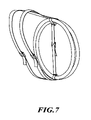
- FIG. 7 is a perspective view of the carrier strapped around a collapsed hula hoop
- FIG. 8 is a top view of an embodiment of a hoop tote.
- FIG. 9 is a detail view of an end intersection.
- FIG. 1 shows a generic backpack-style strap carrier tote 10 according to the preferred embodiment as it is to be laid out on a generally flat surface.
- This embodiment comprises a strap spine 12 , typically made from a length of nylon webbing or canvas ribbon, with a top intersection 14 proximate a first end 16 and a bottom intersection 18 proximate a second end 20 .
- the intersections may be reinforced, e.g., by heavy-duty sewing.
- the shoulder straps are attached to the intersections in “V” shapes (the top portions to the top intersection and the bottom portions to the bottom intersection respectively).
- the “V” shapes may have included angles of any appropriate value; however, it has been found that an included angle in the range of 40 to 90 degrees may be optimal.
- the left shoulder strap may be made as one continuous strap extending from top intersection to bottom intersection or may comprise a top portion 22 attached to the top intersection 14 and a bottom portion 24 attached to the bottom intersection 18 .
- the right shoulder strap may be made as one continuous strap extending from top intersection to bottom intersection or may comprise a top portion 26 attached to the top intersection 14 and a bottom portion 28 attached to the bottom intersection 18 .
- the strap carrier tote 10 may also comprise various buckles linked to strategic locations of said shoulder straps—such as proximate the ends of the shoulder strap portions—to make the invention more adjustable to individual users.
- the top portions of the shoulder straps, 22 and 26 are linked to the female portions of the buckles 50 and 54 respectively, and the bottom portions 24 and 28 are linked to the male portions of the buckles 52 and 56 respectively.
- the female portions 50 and 54 are fixed to the ends of the straps 22 and 26
- the male portions 52 and 56 are linked adjustably to the ends of the straps 24 and 28 .
- FIG. 3 shows how these buckles may cooperate within the invention.
- FIG. 2 shows one species embodiment of the strap carrier tote designed for use with an elongated piece of equipment, such as a rolled yoga mat, exercise mat, sleeping bag, camera tripod, plastic drawing case, etc.
- the buckles of the shoulder straps can be located—and the lengths of the respective shoulder strap portions respectively proportioned—low on the strap and behind the user's arm. This position of the buckles may offer a greater degree of comfort to the user.
- the included angle of the “V” shape may be varied to accommodate taller or shorter users.
- FIG. 3 shows how the equipment item will be held by such equipment straps
- FIG. 2 shows how the equipment strap buckles may be positioned to fasten on the back of the equipment being carried.
- FIG. 3 also shows how the straps may be attached to the top and bottom intersections and how the top and bottom intersections may be placed along the strap spine in acceptable locations so that the spine will be stretched out to its full extent along the user's back. Because the strap spine itself is flexible, gravity and the elongated shape of the piece of equipment will work together to keep the strap spine stretched out and the intersections spaced apart.
- end caps 80 and/or 82 can be added to the top and bottom to further secure the item being carried.
- the end caps 80 and 82 are made from a thin flexible material such as nylon, but in alternate embodiments could be a hard plastic or other rigid material.
- the end caps may be attached to the equipment straps permanently, such as by the sewing of the illustration, or temporarily, such as by snaps, zippers, or VelcroTM.
- the end cap may have an opening 84 to facilitate the insertion of the item to be carried. In this case, the opening is simply a material overlap, but in alternate embodiments, it could be accomplished with snaps, zippers, VelcroTM, or the like.
- FIG. 4 shows the yoga mat tote embodiment laid out on a generally flat surface.
- the equipment straps are intended to gird a generally tubular item, they are affixed at the intersections (top straps to top intersection and bottom straps to bottom intersection respectively) generally in a cross pattern relative to the strap spine 12 .
- the top equipment strap may be made as one continuous strap looping from the top intersection back to the top intersection or may comprise a left portion 30 attached to the top intersection 14 and a right portion 32 attached to the top intersection 14 .
- the bottom equipment strap may be made as one continuous strap looping from the bottom intersection back to the bottom intersection or may comprise a left portion 34 attached to the bottom intersection 18 and a right portion 36 attached to the bottom intersection 18 .
- the equipment straps may also comprise various buckles linked to said equipment straps at strategic locations—such as proximate the ends of the equipment strap portions—to make the invention more adjustable to different items of equipment.
- the male/female type of buckles are illustrated, but other types of buckles or appropriate fasteners could be used.
- FIG. 5 simply shows in detail the bottom intersection 18 of the yoga tote embodiment of the strap carrier tote with buckles at the ends of the equipment strap portions.
- the intersection 18 may be reinforced by heavy-duty sewing or with additional material or in any other appropriate manner.
- the “V” shape is shown at a generally 90 degree included angle 38 ; however, the included angle may vary in different designs—to accommodate different equipment styles or different users.
- the user To use the strap carrier to carry an elongated piece of equipment such as a rolled yoga mat, the user lays out the strap carrier so that the equipment straps are accessible (probably on a generally flat surface). Next, or prior to that step, the user prepares the equipment by rolling up the mat, folding the tripod, sliding into the case, or whatever is applicable, and aligns said prepared piece with the strap spine. Next, the user secures the equipment straps around the piece of equipment, perhaps by fastening and/or adjusting the buckles of the equipment straps. Once the equipment is secure, the user can mount the carrier tote on the user's back by securing the shoulder straps around the user's shoulders, perhaps by fastening and/or adjusting the buckles of the shoulder straps.
- FIG. 6 shows another species embodiment of the strap carrier tote designed for use with a collapsed hula hoop or other toric-shaped or disc-shaped piece of exercise equipment, such as a snow saucer or other.
- the buckles of the shoulder straps can be located—and the lengths of the respective shoulder strap portions respectively proportioned—low on the strap and behind the user's arm—similar to the previous embodiment.
- the strap spine of the carrier tote can also be made adjustable with the addition of a central buckle or other appropriate element.
- FIG. 7 shows how the equipment item will be held by such equipment straps
- FIG. 6 shows how the equipment strap buckles may be positioned to fasten on the back of the equipment being carried.
- FIG. 8 shows how the straps may be attached to the top and bottom intersections and how the strap spine itself is made adjustable with a central buckle, which will typically be buckled in tension during use. In this embodiment, the shape of the equipment item itself will keep the intersections and the equipment straps spaced apart.
- FIG. 8 further shows the hoop tote embodiment laid out on a generally flat surface.
- the equipment straps are intended to gird sections of the hoop itself, said sections of which are being held generally in a cross pattern relative to the strap spine, the equipment straps are attached to the intersections (top straps to top intersection and bottom straps to bottom intersection respectively) in generally straight-line patterns.
- the equipment straps could be made from a different material and attached at the intersections by heavy-duty sewing, application of adhesive, or some other applicable method.
- the top equipment strap may be made as one continuous strap looping from the top intersection back to the top intersection or may comprise an upper portion 40 attached to the top intersection 14 and a lower portion 42 attached to the top intersection 14 (which may be coincident with the strap spine itself).
- the bottom equipment strap may be made as one continuous strap looping from the bottom intersection back to the bottom intersection or may comprise an upper portion 44 attached to the bottom intersection 18 (which may be coincident with the strap spine itself) and a lower portion 46 attached to the bottom intersection 18 .
- the equipment straps may also comprise various buckles at strategic locations—such as proximate the ends of the equipment strap portions—to make the invention more adjustable to different items of equipment.
- these buckles may be affixed directly to the strap spine at the appropriate locations.
- FIG. 8 Also shown in FIG. 8 is an alternate type of buckle for the shoulder straps.
- both of the top portions (right and left) of the shoulder straps 60 and 62 have buckles 64 and 66 at the ends, and the lower portions of the shoulder straps 68 and 70 simply thread into the buckles as shown in FIG. 7 .
- the distal ends of the straps 68 and 70 may be reinforced after they are threaded through the buckles so that they won't pull out—such as by doubling the material, adding heavy-duty sewing, attaching a small end cap, etc.
- the adjusting strap is on the lower portion so that a user can easily lengthen or shorten the shoulder straps while wearing the invention on her back.
- FIG. 8 also shows the central adjusting buckle 72 .
- FIG. 9 simply shows in detail the bottom intersection 18 of the hoop tote embodiment of the strap carrier tote with buckles at the ends of the equipment strap portions.
- the intersection 18 may be reinforced by heavy-duty sewing or with additional material or adhesive or in any other appropriate manner.
- the strap spine may be provided in two portions and the central adjustable buckle may be applied.
- the “V” shape is shown at a generally 90 degree included angle; however, the included angle may vary in different designs—to accommodate different equipment styles or different users.
- the user To use the strap carrier to carry a toric- or disc-shaped piece of equipment such as a collapsed hula hoop, the user lays out the strap carrier so that the equipment straps are accessible (probably on a generally flat surface). Next, or prior to that step, the user prepares the equipment by collapsing the hula hoop into a compact size of small diameter, or whatever is applicable, and aligns said prepared piece with the strap
Abstract
Description
Claims (2)
Priority Applications (1)
| Application Number | Priority Date | Filing Date | Title |
|---|---|---|---|
| US12/122,415 US7971763B2 (en) | 2007-05-17 | 2008-05-16 | Backpack-style strap carrier tote |
Applications Claiming Priority (2)
| Application Number | Priority Date | Filing Date | Title |
|---|---|---|---|
| US93079307P | 2007-05-17 | 2007-05-17 | |
| US12/122,415 US7971763B2 (en) | 2007-05-17 | 2008-05-16 | Backpack-style strap carrier tote |
Publications (2)
| Publication Number | Publication Date |
|---|---|
| US20080283566A1 US20080283566A1 (en) | 2008-11-20 |
| US7971763B2 true US7971763B2 (en) | 2011-07-05 |
Family
ID=40026481
Family Applications (1)
| Application Number | Title | Priority Date | Filing Date |
|---|---|---|---|
| US12/122,415 Expired - Fee Related US7971763B2 (en) | 2007-05-17 | 2008-05-16 | Backpack-style strap carrier tote |
Country Status (1)
| Country | Link |
|---|---|
| US (1) | US7971763B2 (en) |
Cited By (16)
| Publication number | Priority date | Publication date | Assignee | Title |
|---|---|---|---|---|
| US20100282797A1 (en) * | 2009-05-06 | 2010-11-11 | Draeger Safety Uk Limited | Shoulder strap |
| US20140008403A1 (en) * | 2011-02-07 | 2014-01-09 | Skiox As | Foldable Carrying Device |
| US20140091119A1 (en) * | 2012-10-01 | 2014-04-03 | Kristen Racanati | Strap-type carrier and shoulder strap pad with integrated cover for carrier |
| US8733789B1 (en) | 2011-08-08 | 2014-05-27 | Alison C. Kinnear | Sleeve for lap and shoulder belt to reduce wear on apparel |
| US20150076202A1 (en) * | 2013-09-17 | 2015-03-19 | John V. Jensen | Utility bucket backpack apparatus |
| US20150225032A1 (en) * | 2014-02-12 | 2015-08-13 | Portage World-Wide, Inc. | Adjustable Bag Harness For A Bicycle |
| USD758072S1 (en) * | 2015-01-30 | 2016-06-07 | Tamlorn Chase | Surfboard carrier |
| USD759374S1 (en) * | 2015-02-17 | 2016-06-21 | Nadia Cheung-Costanza | Yoga mat strap |
| US20160338474A1 (en) * | 2015-05-19 | 2016-11-24 | Jeffery J. Colvin | Bag carrying device |
| US20170096311A1 (en) * | 2015-10-02 | 2017-04-06 | Michael Davin Godfrey | Mat rolling apparatatus and method |
| USD784692S1 (en) * | 2016-01-11 | 2017-04-25 | YogaHustle, Inc. | Exercise equipment carrying apparatus |
| US9961987B1 (en) * | 2017-04-27 | 2018-05-08 | Toney Harper | Apparatus for hands-free transport of an elongated narrow object |
| USD819970S1 (en) * | 2017-02-03 | 2018-06-12 | Jonathan Jess Morales | Snowboard harness |
| US10039368B2 (en) | 2015-07-31 | 2018-08-07 | Adella Products, Llc | Strapping system |
| US10362883B1 (en) * | 2017-02-21 | 2019-07-30 | Leann L. Bellini | Unitary, continuous and linear apparatus having dual functionality for transporting and securing cover to a seating or resting device |
| USD875851S1 (en) * | 2018-10-03 | 2020-02-18 | Elena Cornelia Savino Ben | Carrier for yoga mat and the like |
Families Citing this family (11)
| Publication number | Priority date | Publication date | Assignee | Title |
|---|---|---|---|---|
| US20090276957A1 (en) * | 2008-05-07 | 2009-11-12 | Boitet-Ball Amanda K | Mat with gel-containing layer and carriers therefor |
| US8454484B2 (en) | 2010-06-11 | 2013-06-04 | Brian T. Keen | Closed loop device incorporating one or more indecomposable knots and methods of using |
| EP2684582A4 (en) * | 2011-03-09 | 2014-08-20 | Rodriguez Fernando Conde | Device for transporting skiing equipment |
| US20140014697A1 (en) * | 2011-06-14 | 2014-01-16 | Function LLC | Sports Equipment Carrying System |
| JP2013216348A (en) * | 2012-04-06 | 2013-10-24 | Yamato−Nb株式会社 | Shoulder carrier |
| US20130299535A1 (en) * | 2012-05-14 | 2013-11-14 | Aaron Lee Lapointe | Multiple Item Carrying Assembly |
| US20140069970A1 (en) * | 2012-09-11 | 2014-03-13 | Mantis Mats, Llc | Yoga mat carrying bag assembly |
| USD801044S1 (en) * | 2013-05-04 | 2017-10-31 | Elizabeth Griffin | Exercise mat carrying strap |
| US20150189975A1 (en) * | 2014-01-06 | 2015-07-09 | Karen Anne Gardner | Recreational Board Carrier |
| US11452925B2 (en) | 2019-01-21 | 2022-09-27 | Emi Shiga | Yoga mat carriers |
| USD948871S1 (en) * | 2020-09-16 | 2022-04-19 | Ana Teresa Azpurua Baez | Handle |
Citations (18)
| Publication number | Priority date | Publication date | Assignee | Title |
|---|---|---|---|---|
| US995458A (en) * | 1909-02-24 | 1911-06-20 | Frederick Charles Harriman | Pack-carrier. |
| US2715989A (en) * | 1952-05-02 | 1955-08-23 | Arne V Sjodin | Shoulder harness |
| US4911347A (en) * | 1988-09-28 | 1990-03-27 | Wilhite Daniel W | Carrier and locking seal for articulated drawing tubes and other cylindrical objects with slip on end caps |
| USD311813S (en) * | 1987-05-11 | 1990-11-06 | Oliver Layne T | Rifle backpack |
| US5437401A (en) * | 1994-02-07 | 1995-08-01 | Seltzer; Richard | Personal harness for carrying articles |
| US5490806A (en) | 1994-08-09 | 1996-02-13 | Spector; Donald | Toy hoop |
| US5664721A (en) * | 1996-04-04 | 1997-09-09 | Homeyer; Gregory M. | Backpack-style firearm/bow/fishing rod carrier |
| USD389642S (en) | 1995-08-04 | 1998-01-27 | Nancy Lee Nadel | Exercise and yoga mat shoulder bag |
| US6491196B1 (en) | 2000-03-15 | 2002-12-10 | Maria Coler | Yoga mat holder |
| US6751816B1 (en) | 2003-04-17 | 2004-06-22 | Barbara Wechsler | Exercise mat ensemble and method of use |
| US20040250346A1 (en) | 2003-06-11 | 2004-12-16 | Vishal Vasishth | Anti-slip multi-layer yoga mat |
| US6889882B1 (en) * | 2002-07-19 | 2005-05-10 | Michael S. Leep | Backpack strap system for carrying loads of various sizes and/or shapes |
| US20050172402A1 (en) | 2004-02-05 | 2005-08-11 | Carly Uretzky-Miller | Yoga mat carry bag |
| US20060043135A1 (en) | 2004-08-24 | 2006-03-02 | Lindsey Susan M | Breathable mesh backsack with straps |
| US7007322B2 (en) | 2002-09-17 | 2006-03-07 | Dawnn Alane | Yoga/exercise mat |
| US20060160672A1 (en) | 2002-04-24 | 2006-07-20 | Appleby Anne E | Yoga force exercise mat with built in carry straps and wallet |
| USD530512S1 (en) | 2005-04-04 | 2006-10-24 | Karen Palaszek | Yoga mat carrier |
| US20060246817A1 (en) * | 2005-04-28 | 2006-11-02 | Wham-O Corporation | Collapsible hula hoop and method |
-
2008
- 2008-05-16 US US12/122,415 patent/US7971763B2/en not_active Expired - Fee Related
Patent Citations (18)
| Publication number | Priority date | Publication date | Assignee | Title |
|---|---|---|---|---|
| US995458A (en) * | 1909-02-24 | 1911-06-20 | Frederick Charles Harriman | Pack-carrier. |
| US2715989A (en) * | 1952-05-02 | 1955-08-23 | Arne V Sjodin | Shoulder harness |
| USD311813S (en) * | 1987-05-11 | 1990-11-06 | Oliver Layne T | Rifle backpack |
| US4911347A (en) * | 1988-09-28 | 1990-03-27 | Wilhite Daniel W | Carrier and locking seal for articulated drawing tubes and other cylindrical objects with slip on end caps |
| US5437401A (en) * | 1994-02-07 | 1995-08-01 | Seltzer; Richard | Personal harness for carrying articles |
| US5490806A (en) | 1994-08-09 | 1996-02-13 | Spector; Donald | Toy hoop |
| USD389642S (en) | 1995-08-04 | 1998-01-27 | Nancy Lee Nadel | Exercise and yoga mat shoulder bag |
| US5664721A (en) * | 1996-04-04 | 1997-09-09 | Homeyer; Gregory M. | Backpack-style firearm/bow/fishing rod carrier |
| US6491196B1 (en) | 2000-03-15 | 2002-12-10 | Maria Coler | Yoga mat holder |
| US20060160672A1 (en) | 2002-04-24 | 2006-07-20 | Appleby Anne E | Yoga force exercise mat with built in carry straps and wallet |
| US6889882B1 (en) * | 2002-07-19 | 2005-05-10 | Michael S. Leep | Backpack strap system for carrying loads of various sizes and/or shapes |
| US7007322B2 (en) | 2002-09-17 | 2006-03-07 | Dawnn Alane | Yoga/exercise mat |
| US6751816B1 (en) | 2003-04-17 | 2004-06-22 | Barbara Wechsler | Exercise mat ensemble and method of use |
| US20040250346A1 (en) | 2003-06-11 | 2004-12-16 | Vishal Vasishth | Anti-slip multi-layer yoga mat |
| US20050172402A1 (en) | 2004-02-05 | 2005-08-11 | Carly Uretzky-Miller | Yoga mat carry bag |
| US20060043135A1 (en) | 2004-08-24 | 2006-03-02 | Lindsey Susan M | Breathable mesh backsack with straps |
| USD530512S1 (en) | 2005-04-04 | 2006-10-24 | Karen Palaszek | Yoga mat carrier |
| US20060246817A1 (en) * | 2005-04-28 | 2006-11-02 | Wham-O Corporation | Collapsible hula hoop and method |
Cited By (22)
| Publication number | Priority date | Publication date | Assignee | Title |
|---|---|---|---|---|
| US20100282797A1 (en) * | 2009-05-06 | 2010-11-11 | Draeger Safety Uk Limited | Shoulder strap |
| US8376201B2 (en) * | 2009-05-06 | 2013-02-19 | Draeger Safety Uk Limited | Shoulder strap |
| US20140008403A1 (en) * | 2011-02-07 | 2014-01-09 | Skiox As | Foldable Carrying Device |
| US9648940B2 (en) * | 2011-02-07 | 2017-05-16 | Skiox As | Foldable carrying device |
| US8733789B1 (en) | 2011-08-08 | 2014-05-27 | Alison C. Kinnear | Sleeve for lap and shoulder belt to reduce wear on apparel |
| US20140091119A1 (en) * | 2012-10-01 | 2014-04-03 | Kristen Racanati | Strap-type carrier and shoulder strap pad with integrated cover for carrier |
| US20150076202A1 (en) * | 2013-09-17 | 2015-03-19 | John V. Jensen | Utility bucket backpack apparatus |
| US9072366B2 (en) * | 2013-09-17 | 2015-07-07 | John V. Jensen | Utility bucket backpack apparatus |
| US9440696B2 (en) * | 2014-02-12 | 2016-09-13 | Portage World-Wide, Inc. | Adjustabable bag harness for a bicycle |
| US20150225032A1 (en) * | 2014-02-12 | 2015-08-13 | Portage World-Wide, Inc. | Adjustable Bag Harness For A Bicycle |
| USD758072S1 (en) * | 2015-01-30 | 2016-06-07 | Tamlorn Chase | Surfboard carrier |
| USD759374S1 (en) * | 2015-02-17 | 2016-06-21 | Nadia Cheung-Costanza | Yoga mat strap |
| US20160338474A1 (en) * | 2015-05-19 | 2016-11-24 | Jeffery J. Colvin | Bag carrying device |
| US10039368B2 (en) | 2015-07-31 | 2018-08-07 | Adella Products, Llc | Strapping system |
| US20170096311A1 (en) * | 2015-10-02 | 2017-04-06 | Michael Davin Godfrey | Mat rolling apparatatus and method |
| US9688496B2 (en) * | 2015-10-02 | 2017-06-27 | Michael Davin Godfrey | Mat rolling apparatatus and method |
| USD784692S1 (en) * | 2016-01-11 | 2017-04-25 | YogaHustle, Inc. | Exercise equipment carrying apparatus |
| USD819970S1 (en) * | 2017-02-03 | 2018-06-12 | Jonathan Jess Morales | Snowboard harness |
| US10362883B1 (en) * | 2017-02-21 | 2019-07-30 | Leann L. Bellini | Unitary, continuous and linear apparatus having dual functionality for transporting and securing cover to a seating or resting device |
| US9961987B1 (en) * | 2017-04-27 | 2018-05-08 | Toney Harper | Apparatus for hands-free transport of an elongated narrow object |
| USD875851S1 (en) * | 2018-10-03 | 2020-02-18 | Elena Cornelia Savino Ben | Carrier for yoga mat and the like |
| USD884342S1 (en) * | 2018-10-03 | 2020-05-19 | Elena Cornelia Savino Ben | Carrier for yoga mat and the like with hanging bag |
Also Published As
| Publication number | Publication date |
|---|---|
| US20080283566A1 (en) | 2008-11-20 |
Similar Documents
| Publication | Publication Date | Title |
|---|---|---|
| US7971763B2 (en) | Backpack-style strap carrier tote | |
| US6179175B1 (en) | Child's knapsack harness and method of use therefor | |
| US5230451A (en) | Harness for neck-worn articles | |
| US7028873B1 (en) | Backpack with lumbar support plate | |
| US9775428B2 (en) | Portable container holder | |
| US20060186150A1 (en) | Item carrier | |
| US6640359B1 (en) | Yoga mat | |
| US7641085B2 (en) | Combination umbrella, support and method of use | |
| US5820575A (en) | Abdominal support belt | |
| CN102469869B (en) | Child carrier | |
| US6102877A (en) | Arm sling | |
| JP2003521968A (en) | Ergonomic book pack | |
| US5954254A (en) | Carrier belt for golf bag | |
| US9737122B1 (en) | Convertible backpack handbag | |
| US11000109B2 (en) | Device for carrying shoulder bags | |
| US20100102098A1 (en) | Skateboard sling | |
| WO2019236498A1 (en) | Bag carrier | |
| GB2498024A (en) | A sling bag | |
| US5996871A (en) | Carrier belt for golf bag | |
| JP2001218779A (en) | Posture correcting corset for upper half body | |
| US10638827B1 (en) | Modular hip belt with gross and fine adjustment | |
| US5666678A (en) | Ground covering system | |
| US20070175005A1 (en) | Adjustable buckle with dual tensioning and releasable closure for joining opposite ends of an article | |
| KR200490314Y1 (en) | Multi purpose strap device wearable on upper body | |
| US20030052144A1 (en) | Body-worn harness for lifting and carrying objects |
Legal Events
| Date | Code | Title | Description |
|---|---|---|---|
| REMI | Maintenance fee reminder mailed | ||
| LAPS | Lapse for failure to pay maintenance fees | ||
| FP | Lapsed due to failure to pay maintenance fee |
Effective date: 20150705 |
|
| FEPP | Fee payment procedure |
Free format text: PETITION RELATED TO MAINTENANCE FEES FILED (ORIGINAL EVENT CODE: PMFP); ENTITY STATUS OF PATENT OWNER: SMALL ENTITY |
|
| FEPP | Fee payment procedure |
Free format text: PETITION RELATED TO MAINTENANCE FEES FILED (ORIGINAL EVENT CODE: PMFP); ENTITY STATUS OF PATENT OWNER: SMALL ENTITY |
|
| FEPP | Fee payment procedure |
Free format text: SURCHARGE, PETITION TO ACCEPT PYMT AFTER EXP, UNINTENTIONAL. (ORIGINAL EVENT CODE: M2558); ENTITY STATUS OF PATENT OWNER: SMALL ENTITY |
|
| MAFP | Maintenance fee payment |
Free format text: PAYMENT OF MAINTENANCE FEE, 4TH YR, SMALL ENTITY (ORIGINAL EVENT CODE: M2551); ENTITY STATUS OF PATENT OWNER: SMALL ENTITY Year of fee payment: 4 |
|
| PRDP | Patent reinstated due to the acceptance of a late maintenance fee |
Effective date: 20190107 |
|
| FEPP | Fee payment procedure |
Free format text: PETITION RELATED TO MAINTENANCE FEES GRANTED (ORIGINAL EVENT CODE: PTGR); ENTITY STATUS OF PATENT OWNER: SMALL ENTITY Free format text: PETITION RELATED TO MAINTENANCE FEES GRANTED (ORIGINAL EVENT CODE: PMFG); ENTITY STATUS OF PATENT OWNER: SMALL ENTITY |
|
| PRDP | Patent reinstated due to the acceptance of a late maintenance fee |
Effective date: 20190107 |
|
| STCF | Information on status: patent grant |
Free format text: PATENTED CASE |
|
| FEPP | Fee payment procedure |
Free format text: MAINTENANCE FEE REMINDER MAILED (ORIGINAL EVENT CODE: REM.); ENTITY STATUS OF PATENT OWNER: SMALL ENTITY |
|
| FEPP | Fee payment procedure |
Free format text: 7.5 YR SURCHARGE - LATE PMT W/IN 6 MO, SMALL ENTITY (ORIGINAL EVENT CODE: M2555); ENTITY STATUS OF PATENT OWNER: SMALL ENTITY |
|
| MAFP | Maintenance fee payment |
Free format text: PAYMENT OF MAINTENANCE FEE, 8TH YR, SMALL ENTITY (ORIGINAL EVENT CODE: M2552); ENTITY STATUS OF PATENT OWNER: SMALL ENTITY Year of fee payment: 8 |
|
| FEPP | Fee payment procedure |
Free format text: MAINTENANCE FEE REMINDER MAILED (ORIGINAL EVENT CODE: REM.); ENTITY STATUS OF PATENT OWNER: SMALL ENTITY |
|
| LAPS | Lapse for failure to pay maintenance fees |
Free format text: PATENT EXPIRED FOR FAILURE TO PAY MAINTENANCE FEES (ORIGINAL EVENT CODE: EXP.); ENTITY STATUS OF PATENT OWNER: SMALL ENTITY |
|
| STCH | Information on status: patent discontinuation |
Free format text: PATENT EXPIRED DUE TO NONPAYMENT OF MAINTENANCE FEES UNDER 37 CFR 1.362 |
|
| FP | Lapsed due to failure to pay maintenance fee |
Effective date: 20230705 |