US797170A - Door stile and rail boring machine. - Google Patents
Door stile and rail boring machine. Download PDFInfo
- Publication number
- US797170A US797170A US15180303A US1903151803A US797170A US 797170 A US797170 A US 797170A US 15180303 A US15180303 A US 15180303A US 1903151803 A US1903151803 A US 1903151803A US 797170 A US797170 A US 797170A
- Authority
- US
- United States
- Prior art keywords
- boring
- machine
- shaft
- rail
- carrier
- Prior art date
- Legal status (The legal status is an assumption and is not a legal conclusion. Google has not performed a legal analysis and makes no representation as to the accuracy of the status listed.)
- Expired - Lifetime
Links
Images


Classifications
-
- B—PERFORMING OPERATIONS; TRANSPORTING
- B23—MACHINE TOOLS; METAL-WORKING NOT OTHERWISE PROVIDED FOR
- B23B—TURNING; BORING
- B23B39/00—General-purpose boring or drilling machines or devices; Sets of boring and/or drilling machines
- B23B39/16—Drilling machines with a plurality of working-spindles; Drilling automatons
- B23B39/20—Setting work or tool carrier along a circular index line; Turret head drilling machines
-
- Y—GENERAL TAGGING OF NEW TECHNOLOGICAL DEVELOPMENTS; GENERAL TAGGING OF CROSS-SECTIONAL TECHNOLOGIES SPANNING OVER SEVERAL SECTIONS OF THE IPC; TECHNICAL SUBJECTS COVERED BY FORMER USPC CROSS-REFERENCE ART COLLECTIONS [XRACs] AND DIGESTS
- Y10—TECHNICAL SUBJECTS COVERED BY FORMER USPC
- Y10T—TECHNICAL SUBJECTS COVERED BY FORMER US CLASSIFICATION
- Y10T408/00—Cutting by use of rotating axially moving tool
- Y10T408/36—Machine including plural tools
- Y10T408/365—Axes of tools moving with work during operation
Definitions
- My invention relates to improvements in :machines for boring the Stiles and rails of doors preparatory to the reception el the dowels b y which the parts after being assembled and passing' the gluing' machine are bound together.
- the main object of my invention is to pro- .vide a machine of simple construction and operation and having a greatly-increased capac' ⁇ ity over machines at present in use, one by which all the holes in both stiles and in each end oi2 the rails may be bored at the same time and by which the parts are accurately matched and one which is readily adjustable to any length, breadth, or thickness o1 door stile or rail.
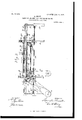
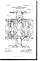
- Alt consists of the parts and the construction and combination of parts hereinalter more fully described, having' reference to the accompanying' drawings, in which'm Figure l is a general 'liront elevation ol the portion of the machine carrying the boring' machanism on line :1; af, Fig. el, certain details lbeing omitted.
- Fig. 2 is a view oit one end oli machine.
- Fig. 3 is a side elevation et one section olf machine, taken irom between the sections.
- Fig. is a view similar to liig. 2 ol one section ol" the machine on a larger se: le.
- Fig. li ⁇ ig. G is a detail el trip mechanism for one ol rail-clamp stops.
- Fig. 7 is a detail of the rail-clamp stops and means for engaging' and tripping' the same.
- Figs. 8 and 9 are dilierent views ot' the clamp mechanism for holding the rails and stiles on their supports during the operation ot' boring.
- Fig. 10 is a side elevation ot' a motor and the bitsha'l't cases.
- Fig. ll is an end view of same. 12 .is a plan of same. l'nig. 13 is a detail of a bit.
- Fig. let is ageneral plan of the machine.
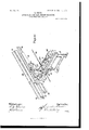
- Fig. l5 is a perspective view, partially broken away, showing particularly the guides 3S and 39, the shafts il?, 48, and 49, and the gear 52 on the shaft 47 and other parts.
- the machine comprises two separated opposed adjustable longitudinal sections duplipates et' each other in all respects, and it will be understood that the description of one section will apply equally to the other.
- Each section includes, essentially, a stationary support or base having transverse ways upon which a bed is adjustable relative to its complcment on the opposite section to doors ot' dilierent widths, a boring-mechanism carrier recil'n'ocable on the bed, and means carried directly on the carrier as an integral feature of the machine for operating the bits.
- a rl. represent opposed stationary central base portions separated a space preferably in excess ol the width et' the widest door to be handled.
- B B are respective and similarly-separated stationary base portions disposed at cach end ot' the machine, the parts B A. .B supporting the mov able superstructure of one section and the parts ly rl/ fl supporting the movable superstructm'e o'll the other section.
- the construction of the section built upon base B A B need only be detailed.
- the superstructure of this section comprises a central bed portieri 3, movable transverse to the axis ol the machine on the ways or tracks 2 of portion A, and the auxiliary end bed portions 3, movable in unison with bed 3 on portions BB.
- the bed portions 3 3v' olI the two sections may be operated simultaneously to advance the rail-supports la 'lli' toward or withdraw them from each other to adapt the machilie to the width of door handled.
- #l is a boring-mechanism carrier supported on bed 3 and having a reciprocating movement intermediate oi the door-rail support la and. the stile-support 37, as will be more fully described hereimil'ter.
- rlhe stile sup porter rest 3T is disposed at the outer edge of the machine parallel and with .its upper surface in the same plane with the rail-support la, and like the latter is rigidly connected to and movable with bed i3.
- rl vertically-adjustable ZA il which forms the immediate support of the boring mechanism, is mounted on screw-stamlards lO on carriera. This vertical adjustment, which.
- ft2 is a wormn shal't jol'n'intled in carrier el; and running parallel with the axis of the machine beneath 1 may be readily increased to four or five or platform 9 and carrying an operating handwheel 43.
- Adjacent to each end of platform 9 is a transverse shaft 44, having a gear 45, engaging a gear on shaft 42.
- Each end of the shafts 44 has a beveled gear engaging a beveled gear-nut 46 on a screw 10.
- the screws on one sidel of the platform may be rightthreaded and those on the other left-threaded, or suitable intermediate gears may be employed, so that in either case the operation of turning the hand-wheel 43 will be to raise or lower the four corners of the platform simultaneously and evenly.
- the boring mechanism comprises a plurality of bit-stocks journaled in boxes 7, which latter are disposed in pairs and slidably mounted on lateral guides on platform 9 and adjustable longitudinally of the machine by suitable clamping means, as indicated at 62, Figs. 10 and 11.
- One of the chief features of my invention is the arrangement of the driving mechanism for the bits, which is here carried direct on the machine and is reciprocable in unison with the carrier.
- the driving mechanism for the bits which is here carried direct on the machine and is reciprocable in unison with the carrier.
- I employ a series of incased motors, as indicated at 6, mounted direct on the carrier-platform and moving with it, each motor operating two gangs of bits, one gang at the outer end of the motor to bore a set of holes in the stile and the other gang at the inner end of the motor to bore a correspond ing set in the door-rail.
- Each pair of boxes 7, supporting a single motor-shaft 6a is provided with the drop projections 63, to which the respective motorcasing is secured.
- rlhese boxes are chambered, as at 64, to accommodate the gears 65 on the motor-shaft and also the gears 66 of the short shafts 6b, which are disposed on each side of shaft 6L and are likewise journaled in the boxes 7 and are provided with bit-sockets at their outer ends.
- the shafts 6b are driven in unison with the motor-shaft, which is also provided with a bit-socket at each end through the interengagement of gears 65 66. Inasmuch as the several bits in each gang ⁇ are driven from the same motorshaft, certain of the bits are left-threaded and others right-threaded.
- journal-caps having each a central opening coincident with chamber 64.
- the latter is filled with oil for the gears 65 66 to run in, and access may be had to the gears through the cap-openings, which are closable by means of the covers 67.
- Vhile ordinarily in this class of work a gang will not contain more than three bits, I have shown a method by which the number even more. Y
- 69 69 represent two auxiliary shafts or bitstocls, disposed one on each side of the motor-casing parallel with and of approximately the length of the motor-shaft and adapted to be intergeared therewith, as indicated at 70 70".
- Shafts 69 are journaled in the end portions of boxes 7.
- the end portions of each pair of boxes are rigidly connected together by means of the tie-rods 72, so that when a motor is put in position on the machine its boxes will surely be in proper alinement, and when they are locked by means of screwclamps 62 in position all twist on a shaft will be obviated and the two sides of the platform will be rigidly united.
- Gears 70 70xL are provided with a suitable housing 73.
- the length of the machine is approximately three times the length of the longest door to be bored.
- the assembled rails and panels (herein referred to simply as incomplete door7) are placed upon the bars 14 14 intermediate of one end of the machine and the beds 3 3', thence delivered by a suitable reciprocating carriage 16 into juxtaposition with the boring mechanism, and finally carried into and deposited in the space between the opposite end of the machine and the beds, where the stiles which have already been bored, glued, and received their dowels may be fitted to the incomplete door while the stiles and assembled rails and panels of a second incomplete door are being admitted to the machine and bored.
- the carriage or conveyer 16 which is adapted to reciprocate between the sections on'dovetailed guides 15, formed on the adjacent sides of bars 14 14, is approximately twice the length of a door and its upper edges are just below the surface of bars 14 14', so that it may freely move beneath the assembled rails and panels, which are supported in their transit through the machine on said bars.
- the forward or feed end rof the carriage is provided with the pivoted dogs 17, adapted to project upward to engage a rail, as 17, Fig. 3, and carry it forward into juxtaposition with the bits.
- the dogs hit a fresh incomplete door, as 17, which has been placed on bars 14 14 ready to be taken between the borers on the next reci procation of the carriage, and are depressed.
- dogs 17 and pins 19 serve as end clamps on the assembled rails and panels to press them together prior to the action oi bars 223.
- the latter are always close enough to the upper surface o1 the rails to prevent them buckling when brought against pins 19.
- the latter are normally depressed beneath the surface of bars ifi 14C' through lthe agency of springs 20 and are only elevated when a projection 2l on the rear end of the carriage engages a spring-pressed cam-linger 22, supported on bed 3, andpushes the camlinger beneath a pin. Un the pin being li'lted a latch 23, Fig.
- the carriers are reciprocated outwardly, the presser-bars 23 lit'ted automatically, and the movement of the rail conveyor or carriage it continued through the machine to deliver the bored rail into the space between the rear end ol the machine and the borers, where .it receives its stiles 'which have previously been bored, glued, iittcd with dowels, and while the workmen are thus tinally putting the parts oli' the door together the rails and stiles ot the next door are being bored.
- the carriage which is approximately twice the length ol a doel', goes back through the machine, it engages the cams 22 just as it reaches the end el its travel and lifts the pins lil again, as described.
- lilach bar is carried on stelns 26, which are adjustable in brackets 27.
- the latter are slidable vertically in the standards 2T, rigid with bed
- the presser-bars are shed with a removable facing 29, of rubber er like suitable material.
- rlhe stems 26 are adjustable by means et the threaded collars 30, which are supported inthe arms 27 and are turnable by hand-wheels 31 to adapt the clamps to rails of dili'erent thickness.
- each stem carries a head 32 to prevent its dropping through the collar, and a spring 33 is interposed between the op* jposite end of the collar and bar 28.
- Springs l i l 33 aiiord a further cushion or yielding support in addition to facing 29, so that the rails or stiles may not be marred or crushed by too great a pressure.
- ,lfhe braclietarms are surrounded by springs Het, by which the arms and clamps are normally made to open to al low the rails to be adniiitted between the facing 2Q and bar '14.
- the presser-bars 28 are operated to descend upon a rail by means of cams 35 on carrier L't engaging the roller-bearing ends ot' levers Btl. lfhese levers are fulu crumed to a part rigidV with bed 3 and have their other ends connected with the arms 27, as seen in Fig. i).
- the stile support or rest 37 is disposed at the outer edge ot' the machine rigid with bed 3, parallel with bars lil, and with its upper surface in the same horizontal plane with said bars. Similar clamping means are employed to clamp the stile upon its rest 21ST. As these means are precisely like those just described to hold the door-rail on the bars ist lli and as they are operated by cams 35 when the carrier it moves outward, it is unnecessary that their construction should be again detailed.
- cams 35 engage levers Sufi to lock the rails ⁇ from above, and when the carrier is moved in the opposite direction cams 35 release those levers and allow springs 3ft to act to lilt the presser-bar 28, while. cams 35 engage levers 3o to operate the stileclanips and hold the stile while it is being bored.
- the portions ol rails Lift lill at the :Front end of the machine and forward ol the boring mechanism are provided with the outer guideflanges 38, Fig. 2, between which a door-rail is held and guided while beingl led Vforward between the bits.
- Each ol these movable guides 3S) consists of a plate or thin metal bar slidable vertically relative to a suitablel guide 41:0 on a. part rigid with bed 3 or 3' and is connected to levers 4.1 tln'ough the medium oit' pins Ln'o'jecting through slots Ll-O in guide-plate 4h).
- Each lever sti is t'ulerumed on a bracket 2T, Figs.
- Figs. 1, 3, 4, 5: 47 48 49 represent the respective drive-shafts for the carriage 16, the carrier 4 and its complement 4', and the bed 3 and its complement 3.
- Shafts 47, 48, and 49 are each journaled in suitable parts rigid with bases A A.
- Shaft 47 has a feather and is slidable in sleeves 51, Fig.
- Shaft 48 is also a feather-shaft and is adapted to be turned to transmit motion to the crank-wheels 54 54 to reciprocate the two boring-mechanism carriers 4 4' simultaneouslyT and in opposite directions. This is done in the following way: Each end of the shaft 48 engages a sleeve 52, journaled in the beds 3 3 and slidable on and turnable with shaft 48.
- Sleeve 52"L carries a beveled gear 53", meshing a similarlygeared crank-wheel 54, journaled in bed 3.
- Shaft 48 transmits power to a second crankwheel 54 at theopposite end of carrier 4 through shaft 55, journaled in base A, and through the feather-shaft 48 and suitable gearing, as indicated in the diagrammatic view Fig. 4.
- Each crankiwheel 54 54 has a pitman 56 connecting' with carrier 4 and similarly'in regard to carrier 4', and when those wheels are turned one complete revolution the boring mechanism is reciprocated completely across beds 3 3, first to bore the stiles, then to bore the rail.
- Shaft 49 by which the movable beds are separated or drawn toward each other, car ries a beveled gear 57 at each end, each gear engaging a corresponding gear 58 on a lineshaft 59, journaled in A B B and which extends from end to end of the machine.
- Shaft v 59 carries adjacent to the front end of carrier 4 a second gear 58.
- the latter and gear 58 engage gears on the transversely-disposed worm-shafts 60, which are also journaled in the stationary parts A B B of the machine.
- Bed 3 is provided with the threaded lug projections 61, engaging each transverse worm- ⁇ shaft 60.
- varare 2 varare 2. lin a machine of the characterdescribed, the combination oi'l two opposed complementary structures each including' a base and a movable bed, an independent, reciprocatory boring' mechanism for each of said structures and including' a carrier and boring-tools, means for supporting material to be bored in the 'path of the carriers, and actuating' mechanism for the carrier, and a reciprocating' conveyer arranged to deliver material to and from the boring-tools.
- a boring-machine the combination o'l two opposed complementary sections adjustable to and 'from each other, means intermediate oi said sections and at the outer sides thercotl for supporting' material to be bored, carriers upon each of said sections reciprocal between said supporting' means of each section, double-ended boring' mechanism on said carriers, means for operating' said carriers simultaneously in opposite d irections, and means including' a reciijnocating' conveyer 'For delivering' material into the path oit the boring' mechanism.
- a boring-machine the combination of a support, separate and parallel work-supports, carriers reciprocal between said worksu pports and a double-ended boring mechanism supported and carried by said carrier, said boring' mechanism comprising' a motor, a motor-shaft, journal-boxes for each end of said shaft, and lateral parallel shafts intereng'ag'ing ⁇ with each end of the motor-shaft.
- each structure including' a base, a bed movable thereon transverse to the axis of the machine, a carrier reciprocal on said bed parallel with the movement ol.E the latter, a vertically-adjustable boringmechanism support on said carrier, boring ⁇ mechanism, rail-supports on the adjacent sides of the beds, a carriage reciprocal between said beds to deliver rails into position between the borers, and clamping' means operatable cordinately with the borilig' mechanism to hold the rails while they are being' bored.
- each structure including a base, a horizontally-adjustable bed, a reciprocating' carrier, boring' nlechanisin, rail-supliiorting means on the adjacent sidcs of the beds, tracks disposed relative to said supporting' means, a carriage reciprocal on said tracks, means on the carriag'e to cng'ag'c a rail to advance it, stop means in the path et the rail so advanced, and means for disengaging' said stop.
- a boring-machine the combination of two opposed complementary structures, each including a base, a bed movable thereon, a carrier reciprocal on said bed, boring mechanism on said carrier, means for supporting' material to be bored intermediate of said structures, a carriage reciprocal between said structures, and several driving mechanisms for the beds, carriers and carriage located adjacent to one end of the machine.
- a boring-machine the combination of two opposed complementary structures, each including a base, a movable bed ⁇ a reciprocating boring-mechanism carrier, boring mechanism on said carrier, said mechanism including a motor, a motor-shaft, journal-boxes for each end of said shaft, and lateral parallel shafts provided with bits engageable with each end of the motor-shaft, and means for supporting ⁇ material to be bored in relation to said carriers, a carriage traversing the space between the carriers, respective connective means between the beds and between the carriers for reciprocating said beds and carriers, said connective means between the former including a worm-shaft journaled in the bases and having oppositely-pitclied threads at its two ends, and means on the beds engaging the threaded portions of said shaft whereby the beds are drawn toward or moved from each other simultaneously.
- a boring-machine the combination of two opposed complementary structures each including a base, a movable bed, a reciprocating boring-meclianism carrier, boring mechanism on said carrier, said mechanism including a motor, a motor-shaft, journal-boxes for each end of said shaft, and lateral parallel shafts provided with bits engageable with each end of the motor-shaft, means for supporting material to be bored relative to said carriei's, means including' a reciprocating conveyer for delivering material between the carriers, connective means between the beds and between the carriers for reciprocating them simultaneously said means for the carriers including a feather-shaft 48, beveled gears slidable on said shaft and crank mechanism operatable through engagement with said gears.
- a boring-machine the combination of two opposed complementary structures, each including a base, a movable bed and a reciprocating boringmechanism carrier, means rigid with a bed for supporting material relative to said carriers, several operative connective means between the beds and between the carriers, a conveyer reciprocal intermediate of said structures, and actuating means for said conveyer including a gear as 52 engaging a rack on the under side of said conveyer.
- a boring-machine the combination of two opposed complementary structures, each including a base, a movable bed and a reciprocatingl boring-mechanism carrier, means carri ed by the bed for supportingmaterial relative to the carriers of each structure, a rail-conveyer reciprocal between the carriers, dogs as- 17 for engaginga rail to carry it into the path of the carriers, stops 19 interposable in the path of the rail so conveyed, and means for operating said dogs and stops relative to the movement of the conveyer and to the carriers.
- a boring-machine the combination of a suitable support, boring mechanism reciprocal thereon, rests to support the material to be bored and disposed in the path of the boring mechanism, a vertically-reciprocal guide as 39 intermediate of a rest, and the corresponding end of the boringmechanism, clamping means for holding the material upon the rests while being bored, and means for operating said clamp and guide eonjunetively with the approach and retreat of the boring mechanism.
- a boring-machine the combination of a suitable support, reciprocatingI boring mechanism thereon, means for effecting such reciproeation, rests to support material to be bored disposed in the path of said boringmechanism, clamps relative to said rests, said clamps includingl a vertically-sliding stem 27 on a part rigid with said boring-inechanism support, a vertically-reciprocating lateral guide-bar 3E and connective means between said gnide-bar and stem sulistantially as described.
- a boring-niaehine a boring mechanism comprising a motor, a motor-sha'li't, journal-boXes for each end of said shaft, and lateral parallel shafts .interengaging with each end of the motor-shaft.
- a boring-machine the combination of opposing rows of journal-boxes; parallel shafts mounted in each row of boxes and provided with driving-gears and boring-bits; a motor located centrally between the rows of boxes; a motor-shaft and journal-boxes for the opposite ends thereof, said shaft provided with a gear-wheel in operative connection with the gear-wheels of the first-named shafts; supplemental shafts parallel with the motor-shaft; journal-boxes for the ends of the supplemental shafts and boring-bits carried by the ends of the sliiiiplemental shafts; a second gear on the motoi-shaftg and gears on the supplemental shaft engaged and driven by the said second gear.
- a boring-machine the combination with a motor, a gang of boring-tools at each side thereof, and interengaging gears between the motor and the boring-tools; of supplemental boring-tools, parallel shafts for the supplemental tools said shafts removably secured, and a supplemental train of gearing between said motor and the supplemental boring-tools.
- a boring-machine provided with a suitable base and adj stable frames mounted upon said base and Lipper reciprocating sec tions adjustably mounted upon said frarnes, tracks formed within the upper sections, suitable carriages, adjusted within said tracks and having bits, and means to operate said bits, said means including a motor on each carriage and provided with a motor-shaft, journal-boxes for each end of said shaft and lateral parallel shafts engageable with each end of the motor-shaft.
- a boring-machine havingl two reciprocati ng tools carrying sections mounted. upon adjustable frames having suitable base, lateral work-supports secured to said frames and a central worli-sugport secured between said frames, a boring-mechanism carrier reciprocal between said central work-simport and a lateral work-support, boring mechanism provided for said carrier and including a motor, a imiter-shaft and lateral shafts removably engageable with each end of said motor-shaft and having bits in combination with means for adjusting' said frames consisting of a suitable rod secured to the base and having right and left handed threads eut thereon, nuts secured to the frames engaging' with the threads of the rod and means for rotating said rod.
- a boring-machine having two parallel sections each reciprocating upon an adjustable frame and a central and two lateral work-seats mounted upon suitable base, in combination with double-ended spindles adjustably secured upon the parallel sections, and having bits secured at their ends and means for transmitting power to each spindle, said means including a motor on each double-ended spindle and intermediate the ends thereof, and lateral parallel spindles interengaging with each end of said double-einled spindles and provided with bits.
Description
8 SHEETS-SHEET 1.
PATENTE?) AUG. l5, 1905.
` [Um/1mg' L. RQT. DOOR STL' AND RAL BORING MAGHNE.
APPLICATION FILED APE. 9, 1903.
l vm
l/MITO@ f am ATTOR EY PATBNTBD AUG.15, 1905.
L. BRODT.. DOOR STILE AND RAIL BORING IVIAOHIIIIEn APPLICATION ILED APR.9,1903.
W/T/WESSES .1
QW hun PATENTED AUG M, 1905.,
No'. "792m,
L. BROD'L 10mm @MLB AND RAIL BORING MAGHINR APPLIUATION FILED APRA), 1903.
ATTORZVY.
` WTNESSES.-
PATENTED AUG. l5, 1905.
L. BROOCH, DOOR SULB AND RAIL BORING MACHINE.
APPLIOATION FILED APB.. 9,1903.
8 SHEETS-SHEET L /NVg/VTOR. Mn
ATTOEY.
PATBNTED AUG. 15, 1905. L1 BMM.
DOR STILE AND RAIL BORING MACHINE.. APPLICATIGN FILED APR. 9. lsoa.
8 SHEETS-SHEET 5.
/T/VESSES- 0% JNVENTo/e. o@ w41 6 (Ln/w! m W6 ATTO f EY.
PATENTED AUG. I5 1905.
L.. BRODT.
DOOR STILE AND RAIL BORING MACHINE.
APPLICATION FILED APR.9,1903.
SHEETS-SHEET 6.
mm KSU ,A om WSN.,
No. 797,170- PATENTED AUG.15, 1905. L. BRDT,
DUUR STILE AND RAIL BORING MACHINE. MPLIGATION FILED- ME. 9, 190s.
B SHEETS-SIIEIIT '1* m lum-lum l wwwwfmunzw. E GRAHAM co. r'uom-Llmcmrmmins` wAsnmavon. n. c.
No. 797,170. PATEN-TED AUG. 15, 1905. L. BRODT. v
DOOR STILE AND RAIL BORING MACHINE.
APPLIUATION FILED APR.9,1903.
8 SHEETS-SHEET 3.
lilltlbl.
LINCOLN BRODT, UF WEST lllflilltlELEY, .,LXLIFORNIA Specification of Letters Patent.
Iliilll lt'l Gi Illll it@ Il-l l hl W Patented lling. 15, 1905.
Application liled April 9, 1903. Serial No. 151,803.
To ,fr/Z who/r1. 'it 'ln/ay concern:
Be it known that LLINCOLN lnojnna citizen et the United States, residing at Vl" est llerkeu ley, county of Alameda, State el California, have invented an improvement in Door Stile and Rail Boring liflachines; and l hereby declaro the following to be a tull, clear, and exact description of the same.
My invention relates to improvements in :machines for boring the Stiles and rails of doors preparatory to the reception el the dowels b y which the parts after being assembled and passing' the gluing' machine are bound together. y
The main object of my invention is to pro- .vide a machine of simple construction and operation and having a greatly-increased capac' `ity over machines at present in use, one by which all the holes in both stiles and in each end oi2 the rails may be bored at the same time and by which the parts are accurately matched and one which is readily adjustable to any length, breadth, or thickness o1 door stile or rail.
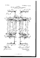
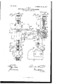
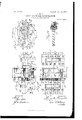
Alt consists of the parts and the construction and combination of parts hereinalter more fully described, having' reference to the accompanying' drawings, in which'm Figure l is a general 'liront elevation ol the portion of the machine carrying the boring' machanism on line :1; af, Fig. el, certain details lbeing omitted. Fig. 2 is a view oit one end oli machine. Fig. 3 is a side elevation et one section olf machine, taken irom between the sections. Fig. el .is a diagrammatic view oli the several main driving mechanisms. Fig. is a view similar to liig. 2 ol one section ol" the machine on a larger se: le. li`ig. G is a detail el trip mechanism for one ol rail-clamp stops. Fig. 7 is a detail of the rail-clamp stops and means for engaging' and tripping' the same. Figs. 8 and 9 are dilierent views ot' the clamp mechanism for holding the rails and stiles on their supports during the operation ot' boring. Fig. 10 is a side elevation ot' a motor and the bitsha'l't cases. Fig. ll is an end view of same. 12 .is a plan of same. l'nig. 13 is a detail of a bit. Fig. let is ageneral plan of the machine. Fig. l5 is a perspective view, partially broken away, showing particularly the guides 3S and 39, the shafts il?, 48, and 49, and the gear 52 on the shaft 47 and other parts.
The machine comprises two separated opposed adjustable longitudinal sections duplipates et' each other in all respects, and it will be understood that the description of one section will apply equally to the other. Each section includes, essentially, a stationary support or base having transverse ways upon which a bed is adjustable relative to its complcment on the opposite section to doors ot' dilierent widths, a boring-mechanism carrier recil'n'ocable on the bed, and means carried directly on the carrier as an integral feature of the machine for operating the bits.
Referring to the drawings, A rl. represent opposed stationary central base portions separated a space preferably in excess ol the width et' the widest door to be handled. B B are respective and similarly-separated stationary base portions disposed at cach end ot' the machine, the parts B A. .B supporting the mov able superstructure of one section and the parts ly rl/ fl supporting the movable superstructm'e o'll the other section. The construction of the section built upon base B A B need only be detailed. The superstructure of this section comprises a central bed portieri 3, movable transverse to the axis ol the machine on the ways or tracks 2 of portion A, and the auxiliary end bed portions 3, movable in unison with bed 3 on portions BB. The parts El forni end supports for the horizontal bar '14, which latter is secured to bed 3 adjacent to the open space between the sections and atl'ords a support lor one side ol a door-rail. il. similar door-rail support ll/ is carried. by the opposite section. tuitable means will be described later by which the bed portions 3 3v' olI the two sections may be operated simultaneously to advance the rail-supports la 'lli' toward or withdraw them from each other to adapt the machilie to the width of door handled.
#l is a boring-mechanism carrier supported on bed 3 and having a reciprocating movement intermediate oi the door-rail support la and. the stile-support 37, as will be more fully described hereimil'ter. rlhe stile sup porter rest 3T is disposed at the outer edge of the machine parallel and with .its upper surface in the same plane with the rail-support la, and like the latter is rigidly connected to and movable with bed i3.
rl vertically-adjustable plattform il, which forms the immediate support of the boring mechanism, is mounted on screw-stamlards lO on carriera. This vertical adjustment, which.
is lier the purpose ol centering the bits relative to the material to be bored, may be elliected in the following manner; ft2 is a wormn shal't jol'n'intled in carrier el; and running parallel with the axis of the machine beneath 1 may be readily increased to four or five or platform 9 and carrying an operating handwheel 43. Adjacent to each end of platform 9 is a transverse shaft 44, having a gear 45, engaging a gear on shaft 42. Each end of the shafts 44 has a beveled gear engaging a beveled gear-nut 46 on a screw 10. The screws on one sidel of the platform may be rightthreaded and those on the other left-threaded, or suitable intermediate gears may be employed, so that in either case the operation of turning the hand-wheel 43 will be to raise or lower the four corners of the platform simultaneously and evenly.
The boring mechanism comprises a plurality of bit-stocks journaled in boxes 7, which latter are disposed in pairs and slidably mounted on lateral guides on platform 9 and adjustable longitudinally of the machine by suitable clamping means, as indicated at 62, Figs. 10 and 11.
One of the chief features of my invention is the arrangement of the driving mechanism for the bits, which is here carried direct on the machine and is reciprocable in unison with the carrier. Heretofore in machines of this class it has been usual to drive the bits from a source external to the boring-mechanism support by a cumbersome system of counter-shafts and belt transmission. In the present instance I employ a series of incased motors, as indicated at 6, mounted direct on the carrier-platform and moving with it, each motor operating two gangs of bits, one gang at the outer end of the motor to bore a set of holes in the stile and the other gang at the inner end of the motor to bore a correspond ing set in the door-rail.
Each pair of boxes 7, supporting a single motor-shaft 6a, is provided with the drop projections 63, to which the respective motorcasing is secured. rlhese boxes are chambered, as at 64, to accommodate the gears 65 on the motor-shaft and also the gears 66 of the short shafts 6b, which are disposed on each side of shaft 6L and are likewise journaled in the boxes 7 and are provided with bit-sockets at their outer ends. The shafts 6b are driven in unison with the motor-shaft, which is also provided with a bit-socket at each end through the interengagement of gears 65 66. Inasmuch as the several bits in each gang` are driven from the same motorshaft, certain of the bits are left-threaded and others right-threaded.
68 represents journal-caps, having each a central opening coincident with chamber 64. The latter is filled with oil for the gears 65 66 to run in, and access may be had to the gears through the cap-openings, which are closable by means of the covers 67.
Vhile ordinarily in this class of work a gang will not contain more than three bits, I have shown a method by which the number even more. Y
69 69 represent two auxiliary shafts or bitstocls, disposed one on each side of the motor-casing parallel with and of approximately the length of the motor-shaft and adapted to be intergeared therewith, as indicated at 70 70". Shafts 69 are journaled in the end portions of boxes 7. The end portions of each pair of boxes are rigidly connected together by means of the tie-rods 72, so that when a motor is put in position on the machine its boxes will surely be in proper alinement, and when they are locked by means of screwclamps 62 in position all twist on a shaft will be obviated and the two sides of the platform will be rigidly united. Gears 70 70xL are provided with a suitable housing 73.
The length of the machine is approximately three times the length of the longest door to be bored. The assembled rails and panels (herein referred to simply as incomplete door7) are placed upon the bars 14 14 intermediate of one end of the machine and the beds 3 3', thence delivered by a suitable reciprocating carriage 16 into juxtaposition with the boring mechanism, and finally carried into and deposited in the space between the opposite end of the machine and the beds, where the stiles which have already been bored, glued, and received their dowels may be fitted to the incomplete door while the stiles and assembled rails and panels of a second incomplete door are being admitted to the machine and bored. The carriage or conveyer 16, which is adapted to reciprocate between the sections on'dovetailed guides 15, formed on the adjacent sides of bars 14 14, is approximately twice the length of a door and its upper edges are just below the surface of bars 14 14', so that it may freely move beneath the assembled rails and panels, which are supported in their transit through the machine on said bars. The forward or feed end rof the carriage is provided with the pivoted dogs 17, adapted to project upward to engage a rail, as 17, Fig. 3, and carry it forward into juxtaposition with the bits. On the return of the carriage to its original position at the feed end of the machine the dogs hit a fresh incomplete door, as 17, which has been placed on bars 14 14 ready to be taken between the borers on the next reci procation of the carriage, and are depressed. Issuingl from beneath incomplete door 17 they are righted by engaging a stop, as 18. As the carriage moves forward with an incomplete door toward the center of the machine it brings the end of the said incomplete door opposite to that engaged by dogs 17 against the pins 19, projecting up through the bars 14 14'. This movement of the said incomplete door has brought it beneath the presser-bars 2S, which are to hold the said incomplete door down while it is being bored,
while dogs 17 and pins 19 serve as end clamps on the assembled rails and panels to press them together prior to the action oi bars 223. The latter, however, are always close enough to the upper surface o1 the rails to prevent them buckling when brought against pins 19. The latter are normally depressed beneath the surface of bars ifi 14C' through lthe agency of springs 20 and are only elevated when a projection 2l on the rear end of the carriage engages a spring-pressed cam-linger 22, supported on bed 3, andpushes the camlinger beneath a pin. Un the pin being li'lted a latch 23, Fig. 6, pivoted to a spring-presscd lever 2st, lulcrumed ou the support of bar lit, engages a notch in the pin and holds it until the lever 24 is actuated to withdraw the latch. When the carriage moves through the machine in the opposite direction to carry a lfresh rail between the borers, the eam 22 moves out Yfrom beneath its pin i9 as soon as the pressure exerted by projection 2l is released; but the pin is left projecting above the rail-support 14; in the path ol. the approaching rail. The rail having' been brought into position between the borers and against pins 1S), the carriage stops, and as the two boring-mechanism carriers 4 #if move in simultaneously toward each other the presser-bars are actuated to clamp the rail down on its supports ist ist, and the levers 2st are engaged by projections on the approaching carriers to release the pins lf). As soon as the borii'lg ot the rail is complete the carriers are reciprocated outwardly, the presser-bars 23 lit'ted automatically, and the movement of the rail conveyor or carriage it continued through the machine to deliver the bored rail into the space between the rear end ol the machine and the borers, where .it receives its stiles 'which have previously been bored, glued, iittcd with dowels, and while the workmen are thus tinally putting the parts oli' the door together the rails and stiles ot the next door are being bored. l/Vhen the carriage, which is approximately twice the length ol a doel', goes back through the machine, it engages the cams 22 just as it reaches the end el its travel and lifts the pins lil again, as described.
'.lhe operation et the presser-bars 28, one et' which is disposed centrally and longitudinally of each section, is as lfollows: lilach bar is carried on stelns 26, which are adjustable in brackets 27. The latter are slidable vertically in the standards 2T, rigid with bed The presser-bars are shed with a removable facing 29, of rubber er like suitable material. rlhe stems 26 are adjustable by means et the threaded collars 30, which are supported inthe arms 27 and are turnable by hand-wheels 31 to adapt the clamps to rails of dili'erent thickness. lfhe outer end of each stem carries a head 32 to prevent its dropping through the collar, and a spring 33 is interposed between the op* jposite end of the collar and bar 28. Springs l i l 33 aiiord a further cushion or yielding support in addition to facing 29, so that the rails or stiles may not be marred or crushed by too great a pressure. ,lfhe braclietarms are surrounded by springs Het, by which the arms and clamps are normally made to open to al low the rails to be adniiitted between the facing 2Q and bar '14. The presser-bars 28 are operated to descend upon a rail by means of cams 35 on carrier L't engaging the roller-bearing ends ot' levers Btl. lfhese levers are fulu crumed to a part rigidV with bed 3 and have their other ends connected with the arms 27, as seen in Fig. i).
The stile support or rest 37 is disposed at the outer edge ot' the machine rigid with bed 3, parallel with bars lil, and with its upper surface in the same horizontal plane with said bars. Similar clamping means are employed to clamp the stile upon its rest 21ST. As these means are precisely like those just described to hold the door-rail on the bars ist lli and as they are operated by cams 35 when the carrier it moves outward, it is unnecessary that their construction should be again detailed. 'lul'lieient to say that when the carrier 4t is moved inwardly tmvard the center ot' the machine to cause the bits to bore the rails cams 35 engage levers Sufi to lock the rails `from above, and when the carrier is moved in the opposite direction cams 35 release those levers and allow springs 3ft to act to lilt the presser-bar 28, while. cams 35 engage levers 3o to operate the stileclanips and hold the stile while it is being bored.
The portions ol rails Lift lill at the :Front end of the machine and forward ol the boring mechanism are provided with the outer guideflanges 38, Fig. 2, between which a door-rail is held and guided while beingl led Vforward between the bits.
3E) represents guides continuous with guides 38, but are movable vertically, so that after the rail has been clamped from above the ends of the portions to be bored may be exposed to the free entry ot' the bits. Each ol these movable guides 3S) consists of a plate or thin metal bar slidable vertically relative to a suitablel guide 41:0 on a. part rigid with bed 3 or 3' and is connected to levers 4.1 tln'ough the medium oit' pins Ln'o'jecting through slots Ll-O in guide-plate 4h). Each lever sti is t'ulerumed on a bracket 2T, Figs. E5 and E), and is connected with braeketarm 27 by means el a link 2T and a projection 2" on arm 2T, operating in a slet'in standard 27. Similar connections operate the stileclamp, so that simultaneously with the engagement oli either the rail or stile presserbars with the rail or stile and antecedent to the entry et the bits into the rail or stile the respective guides b9 35), llig. l, are depressed. rlhey protriule again automatically on the release oi" the clamps.
l,lust as it is necessary te adjust the clam ps to varying thicknesses of rails and Stiles. so is it important to adjust the centers of the bits relative to such variations. This vertical adjustment of the bits is accomplished by a simultaneous movement of the screws 10 to raise or lower platform 9, supporting the motors, as has been seen.
rlhe manner of and means for moving bed l 3 and reciprocating carrier 4 and carriage 16 are as follows, Figs. 1, 3, 4, 5: 47 48 49 represent the respective drive-shafts for the carriage 16, the carrier 4 and its complement 4', and the bed 3 and its complement 3. These shafts eXtend across the space between the sections of the machine and are all grouped adjacent to one end of carrier 4 in as close proximity to each other as is convenient for the proper receipt and transmission of power in order to leave the space through the center of the machine as open as possible. Shafts 47, 48, and 49 are each journaled in suitable parts rigid with bases A A. Shaft 47 has a feather and is slidable in sleeves 51, Fig. 5, journaled in the movable beds of the machine and turnable with shaft 47. Integral with each sleeve, and hence slidable on and turnable with shaft 47, is a gear 52, engaging a rack 53 on the underside of carriage or conveyer 16.
4The feathered portions of the shaft 47 are long enough to accommodate the various adjustments in width of the machine, and according as the shaft is turned in one direction or the other the conveyer-carriage 16 is reciprocated, as before described. Shaft 48 is also a feather-shaft and is adapted to be turned to transmit motion to the crank-wheels 54 54 to reciprocate the two boring-mechanism carriers 4 4' simultaneouslyT and in opposite directions. This is done in the following way: Each end of the shaft 48 engages a sleeve 52, journaled in the beds 3 3 and slidable on and turnable with shaft 48. Sleeve 52"L carries a beveled gear 53", meshing a similarlygeared crank-wheel 54, journaled in bed 3. Shaft 48 transmits power to a second crankwheel 54 at theopposite end of carrier 4 through shaft 55, journaled in base A, and through the feather-shaft 48 and suitable gearing, as indicated in the diagrammatic view Fig. 4.
As these machines maybe thirty feet or more in length, provision must be made to apply power to operate the various movable parts at points such that each part will be moved easily, positively, and without strain. Each crankiwheel 54 54 has a pitman 56 connecting' with carrier 4 and similarly'in regard to carrier 4', and when those wheels are turned one complete revolution the boring mechanism is reciprocated completely across beds 3 3, first to bore the stiles, then to bore the rail. By making the clamping and boring of the two parts successive it enables the workmen to remove the stiles and glue and fit the dowels while the rails are being bored.
ver/,17o
1t has not been deemed essential for purposes of this application to show means for driving shafts 47 48 49. Any convenient and suitable method maybe employed to turn the shafts in either direction to accomplish the results desired.
By this machine all the holes in both stiles may be bored simultaneously, and all the i holes in each end of the rails may be bored simultaneously, and, furthermore, the holes so bored in the stiles and rails will match perfectly.
By having two synchronously-operated boring-carriers with means for automatically delivering rails between them and providing for boring both stiles at the same time it enables all the elements of the door practically to be bored at once and by the one machine. Moreover, by making the boring of the stiles and rails successive the former may be prepared with glue and dowels in readiness for the rail as soon as it comes from the borers. The further advantage in the present construction is obvious in the matter of compactness, economy of power, and eficiency by reason of themounting of the driving mechanism for the bits direct upon the bit-carrier and doing away with the cumberous connections with drive-shafts external to the machine.
As each section of the machine is complete in itself, it is obvious that either could be operated singly, it only being' necessary to provide suitable means for supporting a rail in relation to the bits, in which case the carriage 16 could be dispensed with.
Having thus described my invention, what l claim, and desire to secure by Letters Patent, isev 1. 1n a machine of the class described the combination of two opposed complementary structures, each including a base, a movable bed, a reciprocating boring-mechanism carrier, means for supportingmaterial to be bored in the path of said carrier, a reciprocating conveyer intermediate of th-e sections, and an actuating mechanism for the beds, carriers and conveyer.
3. in a machine of the character described the combination oi two opposed structures each including' a base and a movable bed, a reciprocating' carrier intermediate oi' the sections, means for operating` the carrier, comj'ilementary boring' mechanism slidably mounted on each section, and means for ojjierating' the boring' mechanism.
4f. lin a machine of the class described, the combination oi' two parallel-disposed, complementary supporting-sections transversely adjustable to various door widths, lateral stilesupports carried at the outeredg'es of the sections, work-supports between the sections, reciprocating' (louble-ended boring' mechanisms on said sections operable simultaneously in opposite directions between said stile and work supports and means including' a reci procating' conveyer for delivering' material into the path ot the boring' mechanisms.
5. in a machine ot' the class (flescribed, the combination of two parallel-disposed, complementary sections transversely adjustable to various door widths, lateral stile-supports earried at the outer edges of the sections, railsupports on the adjacent edges of the sections, reciprocating boring' mechanism on said sections operatable simultaneously in opposite directions between said rail and stile supports, and means including' a reciprocating' conveyer between the sections :tor delivering' material into the path of the boring mechanism.
6. ln a machine of the class described, the combination of two parallel-disposed, complementary sections transversely adjustable to various widths, lateral stile-supports, means including' a reciprocating' conveyor `for delivering` rails between said sections preparatory to being' bored, borers on reciprocating' carriers, actuating' mechanism 'for said carriers, clamp means for the rails and stiles, and means for operating; said clamp means cordinately with the movement oi'I the borer-carriers.
7. ln a boring-machine, the combination o'l two opposed complementary sections adjustable to and 'from each other, means intermediate oi said sections and at the outer sides thercotl for supporting' material to be bored, carriers upon each of said sections reciprocal between said supporting' means of each section, double-ended boring' mechanism on said carriers, means for operating' said carriers simultaneously in opposite d irections, and means including' a reciijnocating' conveyer 'For delivering' material into the path oit the boring' mechanism.
8. ln a boring-machine the combination of a support, separate and parallel work-supports, carriers reciprocal between said worksu pports and a double-ended boring mechanism supported and carried by said carrier, said boring' mechanism comprising' a motor, a motor-shaft, journal-boxes for each end of said shaft, and lateral parallel shafts intereng'ag'ing` with each end of the motor-shaft.
i). A boring-machine having' in combination two opposed complementary structures,
each comignising a base, a bed horizontally aded on the platform, means 'for operating' the beds oppositely and simultaneously, means for reciprocating' the carriers oppositely and simultaneonsly, and means rigid and movable with the beds and arranged on both sides of' the beds in the path ol'I the carriers for supporting' material to be bored.
l i. In a boring-machine, the combination of two opposed complementary structures, each structure including' a base, a bed movable thereon transverse to the axis of the machine, a carrier reciprocal on said bed parallel with the movement ol.E the latter, a vertically-adjustable boringmechanism support on said carrier, boring` mechanism, rail-supports on the adjacent sides of the beds, a carriage reciprocal between said beds to deliver rails into position between the borers, and clamping' means operatable cordinately with the borilig' mechanism to hold the rails while they are being' bored.
1Q. l n a boring-machine, the combination of two opposed complementary structures, each structure including a base, a horizontally-adjustable bed, a reciprocating' carrier, boring' nlechanisin, rail-supliiorting means on the adjacent sidcs of the beds, tracks disposed relative to said supporting' means, a carriage reciprocal on said tracks, means on the carriag'e to cng'ag'c a rail to advance it, stop means in the path et the rail so advanced, and means for disengaging' said stop.
13. ln a boring-lnachine, the combination with aXially-alined oppositely-reciprocating borers and suitable supporting' means therelor, oi means intermediate of said borers for supporting` a door, verticallyadjustable clamps situated relative to said supporting means, a reciprocating door-carriage, stop means operatable by the movement of the carriage to clamp the door endwise, and means for operating said vert-ical clamps and releasing said stops conjunctively with the movement of the borers. i
14. In a boring-machine, the combination with aXially-alined oppositely-reciprocating borers and suitable supporting means therefor, of means intermediate thereof for supporting material to be bored, a reciprocating carriage or conveyer situated relative to said -supporting' means, stop means operatable by said conveyer to engage and clamp endwisethe material conveyed, and means in the path of the borers to release automatically said stops.
15. In a boring-machine the combination with oppositely and simultaneously reciprocating borer-carriers and means for eecting such reciproeation, of a movable conveyer traversing the space between said borer-carriers in a line at right angles to the direction of movement of said carriers, stops in the path of said conveyer to clamp material to be bored, and means in conjunction with the borer-carriers to release said stops after the material has been bored.
16. In a boring-machine, the combination with oppositely and simultaneously reciprocating borer-carriers and means for reciprocating said cari'iers, of a movable conveyer intermediate of said carriers, stops operatable by said conveyer to clamp material during the boring operation and means for releasing said stops.
l, 17. In a boring-machine, the combination of oppositely-reciprocating borer-carriers, means for effecting' such reciprocation, a movable conveyer intermediate of said carriers, stops operatable by said conveyer to clamp the material in the line of movement of the conveyer and means in conjunction with the leerer-carriers for automatically releasing said stops.
18. In a boring-machine, the combination of two opposed complementary structures, each including a base, a bed movable thereon, a carrier reciprocal on said bed, boring mechanism on said carrier, means for supporting' material to be bored intermediate of said structures, a carriage reciprocal between said structures, and several driving mechanisms for the beds, carriers and carriage located adjacent to one end of the machine.
19. Ina boring-machine, the combination of two opposed complementary structures, each including a base, a movable bed` a reciprocating boring-mechanism carrier, boring mechanism on said carrier, said mechanism including a motor, a motor-shaft, journal-boxes for each end of said shaft, and lateral parallel shafts provided with bits engageable with each end of the motor-shaft, and means for supporting` material to be bored in relation to said carriers, a carriage traversing the space between the carriers, respective connective means between the beds and between the carriers for reciprocating said beds and carriers, said connective means between the former including a worm-shaft journaled in the bases and having oppositely-pitclied threads at its two ends, and means on the beds engaging the threaded portions of said shaft whereby the beds are drawn toward or moved from each other simultaneously.
20. In a boring-machine, the combination of two opposed complementary structures each including a base, a movable bed, a reciprocating boring-meclianism carrier, boring mechanism on said carrier, said mechanism including a motor, a motor-shaft, journal-boxes for each end of said shaft, and lateral parallel shafts provided with bits engageable with each end of the motor-shaft, means for supporting material to be bored relative to said carriei's, means including' a reciprocating conveyer for delivering material between the carriers, connective means between the beds and between the carriers for reciprocating them simultaneously said means for the carriers including a feather-shaft 48, beveled gears slidable on said shaft and crank mechanism operatable through engagement with said gears.
21. In a boring-machine, the combination of two opposed complementary structures, each including a base, a movable bed and a reciprocating boringmechanism carrier, means rigid with a bed for supporting material relative to said carriers, several operative connective means between the beds and between the carriers, a conveyer reciprocal intermediate of said structures, and actuating means for said conveyer including a gear as 52 engaging a rack on the under side of said conveyer.
22. In a boring-machine, the combination of two opposed complementary structures, each including a base, a movable bed and a reciprocatingl boring-mechanism carrier, means carri ed by the bed for supportingmaterial relative to the carriers of each structure, a rail-conveyer reciprocal between the carriers, dogs as- 17 for engaginga rail to carry it into the path of the carriers, stops 19 interposable in the path of the rail so conveyed, and means for operating said dogs and stops relative to the movement of the conveyer and to the carriers.
23. In a boring-machine the combination of a suitable support, boring mechanism reciprocal thereon, rests to support the material to be bored and disposed in the path of the boring mechanism, a vertically-reciprocal guide as 39 intermediate of a rest, and the corresponding end of the boringmechanism, clamping means for holding the material upon the rests while being bored, and means for operating said clamp and guide eonjunetively with the approach and retreat of the boring mechanism.
24. in a boring-machine, the combination with a suitably-supported reciprocating boring-mechanism carrier, of rests relatively disposed in relation to said carrier upon which material to be bored is supported, a verticallyreciprocal guide movable in relation to a rest and disposed intermediate of the rests and the carrier, clamping means for holdingl the material upon a rest while being' bored, connections between said clamp means and said guide by which the two are operated in unison, and means interposable in the path of the carrier for actuating said clamp means.
ln a boring-machine, the combination of a suitable support, reciprocatingI boring mechanism thereon, means for effecting such reciproeation, rests to support material to be bored disposed in the path of said boringmechanism, clamps relative to said rests, said clamps includingl a vertically-sliding stem 27 on a part rigid with said boring-inechanism support, a vertically-reciprocating lateral guide-bar 3E and connective means between said gnide-bar and stem sulistantially as described.
26. ln a boring-niaehine, a boring mechanism comprising a motor, a motor-sha'li't, journal-boXes for each end of said shaft, and lateral parallel shafts .interengaging with each end of the motor-shaft.
27. ln a boring-machine, the eombinatirim of a motor, a shaft therefor, jonrmthboxes for the ends of the shaft, a double series of oppositely-extending shafts provided with boringbits, a gear on the motor-shaft and gears on the series of shafts engaging and driven by the gear on the motor-shaft.
28. ln a boringa'nachine, the combi nation of opposite rows of journal-boxes; opposite rows of shafts provided with boring bits, said. shafts provided with driven gears; a motor located centrally between the rows of journal-boxes; a motor-shaft; journal-boxes for opposite ends thereof; and a gear on said motor-shaft and disposed between and engaging with the said driven gears.
29. ln a boring-machine, the combination of opposing rows of journal-boxes; parallel shafts mounted in each row of boxes and provided with driving-gears and boring-bits; a motor located centrally between the rows of boxes; a motor-shaft and journal-boxes for the opposite ends thereof, said shaft provided with a gear-wheel in operative connection with the gear-wheels of the first-named shafts; supplemental shafts parallel with the motor-shaft; journal-boxes for the ends of the supplemental shafts and boring-bits carried by the ends of the sliiiiiplemental shafts; a second gear on the motoi-shaftg and gears on the supplemental shaft engaged and driven by the said second gear.
30. ln a boring-machine, the combination with a motor, a gang of boring-tools at each side thereof, and interengaging gears between the motor and the boring-tools; of supplemental boring-tools, parallel shafts for the supplemental tools said shafts removably secured, and a supplemental train of gearing between said motor and the supplemental boring-tools.
31. In a boring-machine provided with a suitable base and adj stable frames mounted upon said base and Lipper reciprocating sec tions adjustably mounted upon said frarnes, tracks formed within the upper sections, suitable carriages, adjusted within said tracks and having bits, and means to operate said bits, said means including a motor on each carriage and provided with a motor-shaft, journal-boxes for each end of said shaft and lateral parallel shafts engageable with each end of the motor-shaft.
32. 1n a boring-machine havingl two reciprocati ng tools carrying sections mounted. upon adjustable frames having suitable base, lateral work-supports secured to said frames and a central worli-sugport secured between said frames, a boring-mechanism carrier reciprocal between said central work-simport and a lateral work-support, boring mechanism provided for said carrier and including a motor, a imiter-shaft and lateral shafts removably engageable with each end of said motor-shaft and having bits in combination with means for adjusting' said frames consisting of a suitable rod secured to the base and having right and left handed threads eut thereon, nuts secured to the frames engaging' with the threads of the rod and means for rotating said rod.
33. A boring-machine having two parallel sections each reciprocating upon an adjustable frame and a central and two lateral work-seats mounted upon suitable base, in combination with double-ended spindles adjustably secured upon the parallel sections, and having bits secured at their ends and means for transmitting power to each spindle, said means including a motor on each double-ended spindle and intermediate the ends thereof, and lateral parallel spindles interengaging with each end of said double-einled spindles and provided with bits.
.ln witness whereolI l have hereunto set my hand.
LlNUGLN .RHODE lllitnesses:
F. l?. iberica, A. A. Pon'rm-i.
Priority Applications (1)
| Application Number | Priority Date | Filing Date | Title |
|---|---|---|---|
| US15180303A US797170A (en) | 1903-04-09 | 1903-04-09 | Door stile and rail boring machine. |
Applications Claiming Priority (1)
| Application Number | Priority Date | Filing Date | Title |
|---|---|---|---|
| US15180303A US797170A (en) | 1903-04-09 | 1903-04-09 | Door stile and rail boring machine. |
Publications (1)
| Publication Number | Publication Date |
|---|---|
| US797170A true US797170A (en) | 1905-08-15 |
Family
ID=2865659
Family Applications (1)
| Application Number | Title | Priority Date | Filing Date |
|---|---|---|---|
| US15180303A Expired - Lifetime US797170A (en) | 1903-04-09 | 1903-04-09 | Door stile and rail boring machine. |
Country Status (1)
| Country | Link |
|---|---|
| US (1) | US797170A (en) |
-
1903
- 1903-04-09 US US15180303A patent/US797170A/en not_active Expired - Lifetime
Similar Documents
| Publication | Publication Date | Title |
|---|---|---|
| US797170A (en) | Door stile and rail boring machine. | |
| US1137854A (en) | Doweling-machine. | |
| US2194757A (en) | Finishing machine | |
| US1823200A (en) | Woodworking machine | |
| US2636525A (en) | Tie pinning machine and method | |
| US1195852A (en) | Tie-boring machine | |
| US694784A (en) | Automatic drilling-machine. | |
| US642073A (en) | Mortising-machine. | |
| US2165774A (en) | Automatic drilling and countersinking machine | |
| US793492A (en) | Mortising-machine. | |
| US1340987A (en) | Automatic franking-machine | |
| US2010157A (en) | Boring machine | |
| US1539440A (en) | Nut forming and drilling machine | |
| US1150155A (en) | Wood-polishing machine. | |
| US587321A (en) | Nailing-machine | |
| US350943A (en) | richardson | |
| US766014A (en) | Button-making machine. | |
| DE1169110B (en) | Double hole drilling machine | |
| US645329A (en) | Woodworking-machine. | |
| US1435619A (en) | Carving machine | |
| US1588345A (en) | Stave machine | |
| US494140A (en) | Hollow-chisel mortising-machin e | |
| US974406A (en) | Drilling-machine. | |
| US446792A (en) | Hausser | |
| US451594A (en) | Edwin c |