US7961976B2 - Image data restoration apparatus, imaging apparatus, image data restoration method and computer readable medium storing image data restoration program - Google Patents
Image data restoration apparatus, imaging apparatus, image data restoration method and computer readable medium storing image data restoration program Download PDFInfo
- Publication number
- US7961976B2 US7961976B2 US11/892,783 US89278307A US7961976B2 US 7961976 B2 US7961976 B2 US 7961976B2 US 89278307 A US89278307 A US 89278307A US 7961976 B2 US7961976 B2 US 7961976B2
- Authority
- US
- United States
- Prior art keywords
- image data
- blur
- matrix
- noise
- information
- Prior art date
- Legal status (The legal status is an assumption and is not a legal conclusion. Google has not performed a legal analysis and makes no representation as to the accuracy of the status listed.)
- Expired - Fee Related, expires
Links
Images


Classifications
-
- H—ELECTRICITY
- H04—ELECTRIC COMMUNICATION TECHNIQUE
- H04N—PICTORIAL COMMUNICATION, e.g. TELEVISION
- H04N23/00—Cameras or camera modules comprising electronic image sensors; Control thereof
- H04N23/60—Control of cameras or camera modules
- H04N23/68—Control of cameras or camera modules for stable pick-up of the scene, e.g. compensating for camera body vibrations
Definitions
- the invention relates to an image data restoration apparatus and an image data restoration method for restoring still image data acquired by capturing a subject image by means of an imaging element, and also relates to an imaging apparatus provided with the image data restoration apparatus and a computer readable medium storing an image data restoration program.
- an image processing apparatus photoelectrically converts a subject image and arithmetically processes the image using an arithmetic device such as a computer.
- an arithmetic device such as a computer.
- various techniques/apparatuses have been proposed for restoring degradation of an image due to camera shake or the like upon image capturing.
- blurring or spread of one point of an image, which leads to deterioration of the image, into its surrounding image is mathematically handled as a spread function so that arithmetic processing can be done.
- JP Hei.6-118468 A (corresponding to U.S. Pat. No. 5,365,303) discloses a method for recovering non-blurred image data by extrapolating missing data to find a pseudo inverse matrix of a blur matrix, which is a matrix expression of a spread function, and by multiplying the pseudo inverse matrix and blurred image data.
- JP Hei.6-118468 A since the method of JP Hei.6-118468 A extrapolates the missing data, noise may occur in the recovered image data and image quality may be degraded. JP Hei.6-118468 A does not mention about a countermeasure against this noise at all. If nothing is done for the noise, a good restored image may not be achieved.
- the invention has been made in view of the above circumstances and provides an image data restoration apparatus and an image data restoration method that can recover non-blurred image data from blurred image data while suppressing image quality from being degraded, and also provides an imaging apparatus provided with the image data restoration apparatus or adopting the image data restoration method and a computer readable medium storing an image data restoration program.
- the invention may provide an image data restoration method, a computer readable medium storing an image data restoration program, and an image data restoration apparatus that can reduce the burden of image processing and shorten the processing period of time.
- An image data restoration apparatus restores still image data acquired by capturing a subject image with an imaging element, on a basis of blur information regarding blur in a one-dimensional direction of the imaging element upon image capturing.
- the image data restoration apparatus includes an image data recovering unit, a noise computing unit and a noise eliminating unit.
- the image data recovering unit multiplies the still image data and a recovery matrix to recover ideal image data.
- the recovery matrix is used to recover, from the still image data, the ideal image data which is acquired upon capturing the subject image in a state where there is no blur based on the blur information.
- the recovery matrix is a pseudo inverse matrix of a blur matrix that represents spread in the one-dimensional direction of the ideal image data due to the blur based on the blur information.
- the noise computing unit computes a plurality of types of noises that derive from the recovery matrix, the plurality of types of noises being periodically superimposed on the image data recovered by the image data recovering unit toward the one-dimensional direction.
- the noise eliminating unit eliminates the noise computed by the noise computing unit, from the image data recovered by the image data recovering unit.
- the recovery matrix is an inverse matrix of an approximate matrix.
- the approximate matrix is obtained by approximating the blur matrix.
- the approximate matrix is defined so as to extrapolate a predetermined value into values of image data that spreads from an end portion of the ideal image data to an outer side in the one-dimensional direction according to the blur based on the blur information.
- the noise computing unit computes the plurality of types of noises on a basis of (i) noise period information regarding a noise superimposition period of each of the plurality of types of noises, the noise period information being computed according to a product of the recovery matrix and the blur matrix, (ii) the image data recovered by the image data recovering unit, and (iii) the still image data.
- the predetermined value may be a value of image data which is in the end portion of the ideal image data.
- the image data restoration apparatus of any one of (1) and (2) may further include a noise period information generating unit that generates the noise period information according to the product of the recovery matrix and the blur matrix.
- the noise computing unit may read the noise period information corresponding to the blur information from a recording medium in which the noise period information corresponding to the blur information is recorded in advance, and use the read noise period information to compute the noises.
- each of the still image data and the image data recovered by the image data recovering unit may have a plurality of pixel data columns arranged in a direction perpendicular to the one-dimensional direction. Each pixel data column is configured to include plural pieces of pixel data aligned in the one-dimensional direction.
- the noise computing unit may include a first sampling unit, a second sampling unit and a dividing unit.
- the first sampling unit samples the pixel data of each pixel data column of the still image data, which is a recovery source of the corresponding pixel data column of the image data recovered by the image data recovering unit, at every noise superimposition period based on the noise period information.
- the second sampling unit samples the pixel data of each pixel data column, which is recovered from the corresponding pixel data column of the still image data as the recovery source, a same number of times as the first sampling unit samples, at every noise superimposition period based the noise period information.
- the dividing unit computes the noises by dividing a value, which is obtained by subtracting an integrated value of the pixel data sampled by the first sampling unit from an integrated value of the pixel data sampled by the second sampling unit, by the number of times of sampling.
- the image data restoration apparatus of any one of (1) to (5) may further include a blur matrix generating unit, an approximate matrix generating unit and a recovery matrix generating unit.
- the blur matrix generating unit generates the blur matrix on the basis of the blur information.
- the approximate matrix generating unit generates the approximate matrix from the blur matrix generated by the blur matrix generating unit.
- the recovery matrix generating unit generates the recovery matrix by computing the inverse matrix of the approximate matrix generated by the approximate matrix generating unit.
- the image data restoration apparatus of any one of (1) to (5) may further include a reading unit that reads the recovery matrix corresponding to the blur information from a recording medium in which the recovery matrix corresponding to the blur information is recorded in advance.
- An imaging apparatus includes the image data restoration apparatus of any one of (1) to (7), the imaging element; a still image data generating unit and a blur information generating unit.
- the still image data generating unit generates the still image data from an output signal of the imaging element.
- the blur information generating unit generates the blur information by detecting blur in the one-dimensional direction of the imaging element upon image capturing.
- An image data restoration method for restoring still image data acquired by capturing a subject image with an imaging element, on a basis of blur information regarding blur in a one-dimensional direction of the imaging element upon image capturing includes: multiplying the still image data and a recovery matrix to recover ideal image data, wherein the recovery matrix is used to recover, from the still image data, the ideal image data which is acquired upon capturing the subject image in a state where there is no blur based on the blur information, and the recovery matrix is a pseudo inverse matrix of a blur matrix that represents spread in the one-dimensional direction of the ideal image data due to the blur based on the blur information; computing a plurality of types of noises that derive from the recovery matrix, the plurality of types of noises being periodically superimposed on the recovered image data toward the one-dimensional direction; and eliminating the computed noise from the recovered image data.
- the recovery matrix is an inverse matrix of an approximate matrix.
- the approximate matrix is obtained by approximating the blur matrix.
- the approximate matrix is defined so as to extrapolate a predetermined value into values of image data that spreads from an end portion of the ideal image data to an outer side in the one-dimensional direction according to the blur based on the blur information.
- the computing of the plurality of types of noises includes computing the plurality of types of noises on a basis of (i) noise period information regarding a noise superimposition period of each of the plurality of types of noises, the noise period information being computed according to a product of the recovery matrix and the blur matrix, (ii) the recovered image data, and (iii) the still image data. (10).
- the predetermined value may be a value of image data which is in the end portion of the ideal image data.
- the image data restoration method of any one of (9) to (10) may further include generating the noise period information according to the product of the recovery matrix and the blur matrix.
- the computing of the noises may further include: reading the noise period information corresponding to the blur information from a recording medium in which the noise period information corresponding to the blur information is recorded in advance, and using the read noise period information to compute the noises.
- each of the still image data and the recovered image data may have a plurality of pixel data columns arranged in a direction perpendicular to the one-dimensional direction.
- Each pixel data column is configured to include plural pieces of pixel data aligned in the one-dimensional direction.
- the computing of the noises may further include: (a) sampling the pixel data of each pixel data column of the still image data, which is a recovery source of the corresponding pixel data column of the recovered image data, at every noise superimposition period based on the noise period information; (b) sampling the pixel data of each pixel data column, which is recovered from the corresponding pixel data column of the still image data as the recovery source, a same number of times as the (a) sampling is performed, at every noise superimposition period based the noise period information; and (c) computing the noises by dividing a value, which is obtained by subtracting an integrated value of the pixel data sampled by the (a) sampling from an integrated value of the pixel data sampled by the (b) sampling, by the number of times of sampling.
- the image data restoration method of any one of (9) to (13) may further include: generating the blur matrix on the basis of the blur information; generating the approximate matrix from the generated blur matrix; and generating the recovery matrix by computing the inverse matrix of the generated approximate matrix.
- the image data restoration method of any one of (9) to (13) may further include reading the recovery matrix corresponding to the blur information from a recording medium in which the recovery matrix corresponding to the blur information is recorded in advance.
- a computer recording medium stores a program causing a computer to execute a process of restoring still image data acquired by capturing a subject image with an imaging element, on a basis of blur information regarding blur in a one-dimensional direction of the imaging element upon image capturing.
- the process includes: multiplying the still image data and a recovery matrix to recover ideal image data, wherein the recovery matrix is used to recover, from the still image data, the ideal image data which is acquired upon capturing the subject image in a state where there is no blur based on the blur information, and the recovery matrix is a pseudo inverse matrix of a blur matrix that represents spread in the one-dimensional direction of the ideal image data due to the blur based on the blur information; computing a plurality of types of noises that derive from the recovery matrix, the plurality of types of noises being periodically superimposed on the recovered image data toward the one-dimensional direction; and eliminating the computed noise from the recovered image data.
- the recovery matrix is an inverse matrix of an approximate matrix. The approximate matrix is obtained by approximating the blur matrix.
- the approximate matrix is defined so as to extrapolate a predetermined value into values of image data that spreads from an end portion of the ideal image data to an outer side in the one-dimensional direction according to the blur based on the blur information.
- the computing of the plurality of types of noises includes computing the plurality of types of noises on a basis of (i) noise period information regarding a noise superimposition period of each of the plurality of types of noises, the noise period information being computed according to a product of the recovery matrix and the blur matrix, (ii) the recovered image data, and (iii) the still image data.
- an image data restoration apparatus that can recover non-blurred image data from blurred image data while suppressing image quality from being degraded can be provided.
- An image data restoration method for restoring a blurred image of a subject includes: setting a one-dimensional direction of blur in the blurred image; computing blur characteristic information, which is expressed by a point spread function indicating spread of an image caused by the blur, based on the set one-dimensional direction; computing an impulse response of the blur characteristic information; and classifying the blur characteristic information by type based on the impulse response.
- An image data restoration method for restoring a blurred image of a subject includes: setting a one-dimensional direction of blur in the blurred image; computing blur characteristic information, which is expressed by a point spread function indicating spread of an image caused by the blur, based on the set one-dimensional direction; and classifying the blur characteristic information by type by factorizing an inverse blur characteristic function expressed by an inverse function of the point spread function.
- the inverse blur characteristic function may be expressed by a polynomial of predetermined variable representing pixel position information.
- the image data restoration method may further include: determining as to whether or not a coefficient of each term of the polynomial is equal to 0; and after the determining, detecting a magnitude relation between the coefficients of the terms of the polynomial.
- the classifying may classify the blur characteristic information by type based on the detected magnitude relation.
- the process includes: setting a one-dimensional direction of blur in the blurred image; computing blur characteristic information, which is expressed by a point spread function indicating spread of an image caused by the blur, based on the set one-dimensional direction; computing an impulse response of the blur characteristic information; and classifying the blur characteristic information by type based on the impulse response.
- a computer readable medium stores a program that causes a computer to execute a process for restoring a blurred image of a subject.
- the process includes: setting a one-dimensional direction of blur in the blurred image; computing blur characteristic information, which is expressed by a point spread function indicating spread of an image caused by the blur, based on the set one-dimensional direction; and classifying the blur characteristic information by type by factorizing an inverse blur characteristic function expressed by an inverse function of the point spread function.
- the inverse blur characteristic function may be expressed by a polynomial of a predetermined variable representing pixel position information.
- the process may further include: determining as to whether or not a coefficient of each term of the polynomial is equal to 0; and after the determining, detecting a magnitude relation between the coefficients of the terms of the polynomial.
- An image data restoration apparatus for restoring a blurred image of a subject includes a setting unit, a first computing unit, a second computing unit and a classifying unit.
- the setting unit sets a one-dimensional direction of blur in the blurred image.
- the first computing unit computes blur characteristic information, which is expressed by a point spread function indicating spread of an image caused by the blur, based on the set one-dimensional direction.
- the second computing unit computes an impulse response of the blur characteristic information.
- the classifying unit classifies the blur characteristic information by type based on the impulse response.
- An image data restoration apparatus for restoring a blurred image of a subject includes a setting unit, a computing unit and a classifying unit.
- the setting unit sets a one-dimensional direction of blur in the blurred image.
- the computing unit computes blur characteristic information, which is expressed by a point spread function indicating spread of an image caused by the blur, based on the set one-dimensional direction.
- the classifying unit classifies the blur characteristic information by type by factorizing an inverse blur characteristic function expressed by an inverse function of the point spread function.
- the inverse blur characteristic function may be expressed by a polynomial of a predetermined variable representing pixel position information.
- the image data restoration apparatus may further include a detecting unit that determines as to whether or not a coefficient of each term of the polynomial is equal to 0 and then detects a magnitude relation between the coefficients of the terms of the polynomial.
- the classifying unit may classify the blur characteristic information by type based on the detected magnitude relation.
- the image data restoration method of (17) discriminate a type of a filter by acquiring an impulse response of the blur characteristic information while by using the blur characteristic information expressed by a point spread function indicating spread of an image caused by the blur. Also, the image data restoration method of (18) discriminates a type of a filter by factorizing the inverse blur characteristic function expressed by a reciprocal of the blur characteristic information.
- the image data restoration method of (18) can discriminate as to whether or not the inverse blur characteristic function can be solved mathematically, by discriminating coefficient values included in the inverse blur characteristic function.
- an equation can be solved in the one-dimensional direction. At this time, it can be determined that filter processing using the blur characteristic information is proper.
- the inverse blur characteristic function cannot be solved mathematically, the equation cannot be solved in the one-dimensional direction. At this time, it can be determined that filter processing using the blur characteristic information is improper.
- the image data restoration method can reduce the burden of image processing and shorten the processing period of time.
- An image data restoration method for restoring a blurred image of a subject includes: setting a one-dimensional direction of blur in the blurred image; computing blur characteristic information, which is expressed by a point spread function indicating spread of an image caused by the blur, based on the set one-dimensional direction; classifying the blur characteristic information by type; determining spread based on coefficients of the point spread function; and performing filter processing with the blur characteristic information in order of spread of the blur characteristic information from largest.
- the spread may be defined by a range that occupies more than 80% of a total range representing the point spread function.
- the spread may be defined by a standard deviation or variance of the point spread function.
- the image data restoration method of any one of (26) to (28) may further include integrating the blur characteristic information for each type of the blur characteristic information. The spread is determined after the integrating.
- the image data restoration method any one of (26) to (28) may further include computing an impulse response of the blur characteristic information. The type of the blur characteristic information may be determined based on the impulse response.
- a computer readable medium stores a program that causes a computer to execute a process for restoring a blurred image of a subject.
- the process includes: setting a one-dimensional direction of blur in the blurred image; computing blur characteristic information, which is expressed by a point spread function indicating spread of an image caused by the blur, based on the set one-dimensional direction; classifying the blur characteristic information by type; determining spread based on coefficients of the point spread function; and performing filter processing with the blur characteristic information in order of spread of the blur characteristic information from largest.
- the spread may be defined by a range that occupies more than 80% of a total range representing the point spread function.
- the spread may be defined by a standard deviation or variance of the point spread function.
- the process may further include integrating the blur characteristic information for each type of the blur characteristic information. The spread may be determined after the integrating.
- the process may further include computing an impulse response of the blur characteristic information. The type of the blur characteristic information may be determined based on the impulse response.
- An image data restoration apparatus for restoring a blurred image of a subject includes a computing unit, a classifying unit, a determining unit and a filtering unit. The computing unit sets a one-dimensional direction of blur in the blurred image.
- the computing unit computes blur characteristic information, which is expressed by a point spread function indicating spread of an image caused by the blur, based on the set one-dimensional direction.
- the classifying unit classifies the blur characteristic information by type.
- the determining unit determines spread based on coefficients of the point spread function.
- the filtering unit performs filter processing with the blur characteristic information in order of spread of the blur characteristic information from largest.
- the spread may be defined by a range that occupies more than 80% of a total range representing the point spread function.
- the spread may be defined by a standard deviation or variance of the point spread function.
- the determining unit may integrate the blur characteristic information for each type of the blur characteristic information and then determines the spread.
- the classifying unit may compute an impulse response of the blur characteristic information and then, determine the type of the blur characteristic information based on the impulse response.
- the above configuration discriminates a type of blur characteristic information using the blur characteristic information which is expressed by a point spread function indicating spread of an image caused by the blur and discriminates the effect of blur characteristic information for every type. Therefore, the spread of the point spread function of each blur characteristic information is determined.
- a blurred image is a transfer from the original image.
- the above configuration computes, from coefficient values of the point spread function, as to how many pixels of the original image a pixel affecting the blur of the blurred image is transferred from.
- the blurred image can be processed with a suitable filter. Also, by performing filter processing with the blur characteristic information in order of effect of the filter processing from the highest, the number of times of processing can be reduced and the processing period of time and the processing burden can be reduced.
- an image data restoration method a computer readable medium storing an image data restoration program, and an image data restoration apparatus capable of reducing the burden of image processing and shortening the processing period of time.
- An image data restoration method for restoring a blurred image of a subject includes: setting a one-dimensional direction of blur in the blurred image; computing blur characteristic information, which is expressed by a point spread function indicating spread of an image caused by the blur, based on the set one-dimensional direction; classifying the blur characteristic information by type; determining an influence degree of each classified blur characteristic information.
- the influence degree may indicate a susceptibility to an error during correction of the blurred image.
- the influence degree may indicate an effect when the blurred image is restored.
- the image data restoration method of (42) may further include performing filter processing with the blur characteristic in order of the influence degree of the blur characteristic information from largest.
- the point spread function may be expressed by a polynomial of a predetermined variable representing pixel position information.
- the influence degree may be determined on the basis of number of terms included in an inverse function of the point spread function.
- the image data restoration method of any one of (41) to (45) may further include computing an impulse response of the blur characteristic information.
- the classifying may classify the blur characteristic information by type based on the impulse response.
- a computer readable medium stores a program that causes a computer to execute a process for restoring a blurred image of a subject.
- the process includes: setting a one-dimensional direction of blur in the blurred image; computing blur characteristic information, which is expressed by a point spread function indicating spread of an image caused by the blur, based on the set one-dimensional direction; classifying the blur characteristic information by type; and determining an influence degree of each classified blur characteristic information.
- the influence degree may indicate a susceptibility to an error during correction of the blurred image.
- the influence degree may indicate an effect when the blurred image is restored.
- the process may further include performing filter processing with the blur characteristic in order of the influence degree of the blur characteristic information from largest.
- the point spread function may be expressed by a polynomial of a predetermined variable representing pixel position information. The influence degree may be determined on the basis of number of terms included in an inverse function of the point spread function.
- the process may further include computing an impulse response of the blur characteristic information.
- the classifying may classify the blur characteristic information by type based on the impulse response.
- An image data restoration apparatus for restoring a blurred image of a subject includes a computing unit, a classifying unit and a determining unit. The computing unit sets a one-dimensional direction of blur in the blurred image.
- the computing unit computes blur characteristic information, which is expressed by a point spread function indicating spread of an image caused by the blur, based on the set one-dimensional direction.
- the classifying unit classifies the blur characteristic information by type.
- the determining unit determines an influence degree of each classified blur characteristic information.
- the influence degree may indicate a susceptibility to an error during correction of the blurred image.
- the influence degree may indicate an effect when the blurred image is restored.
- the image data restoration apparatus of (54) may further include a filtering unit that performs filter processing with the blur characteristic in order of the influence degree of the blur characteristic information from largest.
- the point spread function may be expressed by a polynomial of a predetermined variable representing pixel position information.
- the determining unit may determine the influence degree on the basis of number of terms included in an inverse function of the point spread function.
- the classifying unit may compute an impulse response of the blur characteristic information, and classifies the blur characteristic information by type based on the impulse response.
- the image data restoration method set forth above determines the influence degree after classifying filter by type while using blur characteristic information which is expressed by a point spread function indicating spread of an image caused by the blur.
- the influence degree is a susceptibility to an error during correction of the blurred image or an effect when the blurred image is restored.
- the influence degree is the susceptibility to an error during the correction of the blurred image
- the influence of error upon the filter processing is large if the influence degree of the blur characteristic information is high. Therefore, the filter processing is first performed for blur characteristic information whose influence degree is high rather than blur characteristic information whose influence degree is low. Since the determined influence degree is referenced when the order of filter processing is determined, the filter processing can be suitably performed based on each classified blur characteristic information while suppressing the influence of error.
- an image data restoration method a computer readable medium storing an image data restoration program, and an image data restoration apparatus capable of reducing the burden of image processing and shortening the processing period of time.
- FIG. 1 is a view showing a schematic configuration of a digital camera having a function for correcting blur due to hand movement for illustrating embodiments of the invention.
- FIG. 2 is a view schematically illustrating recovery of a blurred image.
- FIG. 3 is a view illustrating a method for restoring still image data in which blur occurs.
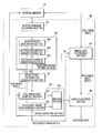
- FIG. 4 is a block diagram showing the internal configuration of an image data restoring section shown in FIG. 1 .
- FIG. 5( a ) is a view showing an example of a blur matrix when an imaging element is blurred at a constant velocity in a one-dimensional direction
- FIG. 5( b ) is a view showing an approximate matrix computed by approximating the blur matrix of FIG. 5( a )
- FIG. 5( c ) is a view showing a recovery matrix which is an inverse matrix of the approximate matrix of FIG. 5( b )
- FIG. 5( d ) is a view showing a matrix obtained from a product of the blur matrix of FIG. 5( a ) and the recovery matrix of FIG. 5( c ).
- FIG. 6( a ) is a view showing an example of a blur matrix when an imaging element is blurred at a constant velocity in a one-dimensional direction
- FIG. 6( b ) is a view showing an approximate matrix computed by approximating the blur matrix of FIG. 6( a )
- FIG. 6( c ) is a view showing a recovery matrix which is an inverse matrix of the approximate matrix of FIG. 6( b )
- FIG. 6( d ) is a view showing a matrix obtained from a product of the blur matrix of FIG. 6( a ) and the recovery matrix of FIG. 6( c ).
- FIG. 7( a ) is a view showing an example of an approximate matrix when an extrapolation operation is carried out by the difference equation of first order
- FIG. 7( b ) is a view showing a recovery matrix which is an inverse matrix of the approximate matrix of FIG. 7( a ) 0
- FIG. 7( c ) is a view showing a matrix obtained from a product of the blur matrix of FIG. 5( a ) and the recovery matrix of FIG. 7( b ).
- FIG. 8( a ) is a view showing an example of an approximate matrix when an extrapolation operation is carried out by the difference equation of a second order
- FIG. 8( b ) is a view showing a recovery matrix which is an inverse matrix of the approximate matrix of FIG. 8( a )
- FIG. 8( c ) is a view showing a matrix obtained from a product of the blur matrix of FIG. 5( a ) and the recovery matrix of FIG. 8( b ).
- FIG. 9 is a flowchart illustrating an operation of the image data restoring section shown in FIG. 1 .
- FIG. 10 is a flowchart showing a procedure of image recovery processing.
- FIG. 11 is a view showing a signal flow of an inverse filter.
- FIG. 12 is a flow diagram showing a procedure for classifying a filter by type on the basis of an inverse blur filter.
- FIG. 13 is a flow diagram showing a procedure for classifying a filter by type on the basis of an inverse blur filter.
- FIG. 14 is a flow diagram showing a procedure for classifying a filter by type on the basis of an inverse blur filter.
- FIG. 15 is a flow diagram showing a procedure separated from the flows shown in FIGS. 12 to 14 .
- FIG. 16 is a view showing spread of blur characteristic information.
- FIG. 17 is a table showing a correspondence relation among a filter type, an influence degree, and filter processing.
- FIG. 18 is a plan view of a blurred image
- FIG. 1 shows a schematic configuration of a digital camera having a function for correcting blur due to hand movement which is an example of an imaging apparatus, for illustrating an embodiment of the invention.
- a digital camera 100 includes an imaging section 1 , an analog signal processing section 2 , an analog to digital (A/D) converting section 3 , a driving section 4 , a blur detecting section 5 , a digital signal processing section 6 , a compression/decompression processing section 7 , a system control section 9 , an internal memory 10 , a media interface (I/F) 11 , a recording medium 12 , an operation section 13 , an image data restoring section 60 , and a system bus 14 .
- I/F media interface
- the system bus 14 is connected to the image data restoring section 60 , the digital signal processing section 6 , the compression/decompression processing section 7 , the system control section 9 , the internal memory 10 , and the medium interface 11 .
- the imaging section 1 includes an optical system having an imaging lens 1 a and an imaging element 1 b , such as a charge coupled device (CCD) type or a complementary metal oxide semiconductor (CMOS) type imaging (area) sensor, that receives light from a subject through the optical system.
- the imaging section 1 captures a subject image and outputs an imaging signal (or analog signal).
- the analog signal processing section 2 performs a predefined analog signal processing on the imaging signal from the imaging section 1 .
- the A/D converting section 3 converts the analog signal on which the signal processing has been performed in the analog signal processing section 2 .
- the driving section 4 drives the imaging element 1 b , the analog signal processing section 2 , and the A/D converting section 3 in accordance with a drive pulse supplied from the system control section 9 .
- the shooting mode is a mode in which the subject can be captured and image data generated from the imaging signal obtained by shooting can be recorded.
- the digital signal processing section 6 performs a digital signal processing on a digital signal from the A/D converting section 3 in accordance with an operating mode set in the operation section 13 and generates captured image data.
- the digital signal processing in the digital signal processing section 6 includes black level correction processing (OB processing), linear matrix correction processing, white balance adjustment processing, gamma correction processing, concurrent processing, and the like.
- This digital signal processing section 6 is implemented with, for example, a digital signal processor (DSP).
- DSP digital signal processor
- the compression/decompression processing section 7 performs compression processing for the captured image data generated by the digital signal processing section 6 and performs decompression processing for compressed image data obtained from the recording medium 12 .
- the internal memory 10 is, for example, a dynamic random access memory (DRAM).
- DRAM dynamic random access memory
- the internal memory 10 is used as a work memory of the digital signal processing section 6 , the system control section 9 and the image data restoring section 60 , and is also used as a buffer memory for temporarily storing the captured image data to be recorded in the recording medium 12 .
- the medium interface 11 performs data input/output with the recording medium 12 such as a memory card.
- the operation section 13 is used to perform various types of operations for the digital camera, and includes a release button (not shown) for instructing shooting.
- the blur detecting section 5 detects blur of the digital camera 100 (having the same meaning as blur of the imaging element 1 b ) during image capturing (exposure) of the imaging element 1 b in accordance with a command from the system control section 9 , generates blur information regarding the detected blur, and outputs the blur information to the system control section 9 .
- the blur information is recorded in the internal memory 10 by the system control section 9 .
- a method for detecting blur may be implemented by a method for detecting blur by means of a sensor such as a gyroscope or a piezoelectric device; or a method for detecting blur by image processing from image data acquired through exposure.
- the method for detecting blur by the image processing may be implemented by a method for obtaining blur from a blur direction of a contour or a method for detecting blur from the blur of a specific mark by inserting the specific mark into a part of the subject and shooting the subject. Since all of these blur detecting methods as described above are well known, description thereon will be omitted here.
- the blur information can be handled by digital signal processing if a blur position is quantized in pixel-interval unit and an intensity of light in the blur position is quantized. If the blur occurs at a constant velocity in a one-dimensional direction, this means that there is no light intensity difference in a range where the blur occurs. Thus, the blur information can have a uniform intensity.
- the blur information generated by the blur detecting section 5 includes a blur direction, a blur size expressed by number of pixels (corresponding to number of photoelectric converting elements of the imaging element 1 b ), and a blur velocity.
- the system control section 9 performs the overall control of the digital camera 100 including a shooting operation.
- the image data restoring section 60 restores the still image data, to thereby recover the still image data which is to be acquired by capturing in a state where there is no blur.
- FIG. 2 is a view schematically illustrating recovery of still image data in which blur occurs.
- an original image is expressed so as to correspond to a pixel arrangement of the imaging element 1 b for capturing a subject image
- light from a plurality of pixels e.g., three pixels in FIG. 2
- blur occurs in the concerned pixel.
- the vertical direction of the drawing is defined as a direction in which the blur occurs.
- a blur direction is set to a predetermined one-dimensional direction and processing which will be described later is performed based on blur information in the one-dimensional direction.
- blur characteristic information expressed by a point spread function spread of an image caused by blur is computed based on the one-dimensional direction of the blur for still image data in which the blur occurs.
- Ideal still image data in which there is no blur is recovered by performing recovery processing that filters the still image data in which the blur occurs using the concerned blur characteristic information as a blur filter.
- FIG. 3( a ) is a schematic view of ideal still image data O, in which there is no blur, generated by the digital signal processing section 6 when the imaging element 1 b captures a subject image in a state where there is no blur.
- a plurality of pixel data columns each including 10 pieces of pixel data that is, pixel data O 1 to O 10 arranged in order in a vertical direction Y are arranged in a horizontal direction X orthogonal to the vertical direction Y.
- 10 pixel data rows each including plural pieces of pixel data arranged in the horizontal direction X are arranged in the vertical direction Y.
- pixel data O 11 and O 12 are pixel data of two pixel data rows acquired from a subject that newly enters a shooting range of the imaging element 1 b when the imaging element 1 b is moved a distance corresponding to two photoelectric converting elements in the Y direction during image capturing.
- the pixel data O 11 and O 12 represent pixel data that spread to a outer side in the Y direction than an end portion of the ideal still image data O (the pixel data O 10 ) due to movement of the imaging element 1 b .
- a matrix expression, in which the pixel data columns shown in FIG. 3( a ) are combined with the pixel data O 11 and the pixel data O 12 continued to the outer side in the Y direction, can be defined as a column vector [O] as follows.
- FIG. 3( b ) is a schematic view of still image data S generated by the digital signal processing section 6 when a subject image is captured in a shaken state while the imaging element 1 b is intended to perform the image capturing to acquire the still image data O.
- the still image data S a plurality of pixel data columns each including 10 pieces of pixel data, that is, pixel data S 1 to S 10 arranged in order in the vertical direction Y are arranged in the horizontal direction X orthogonal to the vertical direction Y.
- 10 pixel data rows each including a plurality of pixel data arranged in the horizontal direction X may be arranged in the vertical direction Y.
- Each pixel data column of the still image data S can be expressed as a column vector [S] as follows.
- the imaging element 1 b is moved a distance corresponding to two photoelectric converting elements in the Y direction upon image capturing when the still image data S is being captured.
- H denotes a blur matrix corresponding to a point spread function (hereinafter, referred to as a blur transfer function) which represents spread of the still image data O in the Y direction caused by this blur and which is expressed in a z region.
- a blur transfer function a point spread function
- the blur matrix H becomes a matrix of 10 rows ⁇ 12 columns and is not regular because the number of pieces of data of [S] is different from that of [O]. For this reason, an inverse matrix of the blur matrix H cannot be computed. Then, a pseudo inverse matrix of the blur matrix H is obtained and set to W, to thereby make it possible to obtain values of [O].
- W is referred to as a “recovery matrix” because W is the matrix for recovering the still image data O.
- the image data restoring section 60 provided in the digital camera of this embodiment has a function for effectively eliminating noise superimposed on the recovered image data O by generating the recovered image data O using the recovery matrix W.
- FIG. 4 is a block diagram showing an internal configuration of the image data restoring section 60 shown in FIG. 1 .
- the image data restoring section 60 is provided with a blur information acquiring section 62 for acquiring blur information (hereinafter, denoted by “A”) from the internal memory 10 ; a recovery matrix setting section 63 for setting a recovery matrix W on the basis of the blur information A; an image data recovering section 64 for recovering the ideal image data O by multiplying the recovery matrix W set by the recovery matrix setting section 63 and the still image data S corresponding to the blur information A recorded in the internal memory 10 ; a noise period information generating section 67 for generating noise period information regarding a superimposition period and a type of noise which derives from the recovery matrix W and which is periodically superimposed in the Y direction on each pixel data column of the recovered image data O recovered by the image data recovering section 64 set in the recovery matrix setting section 63 ; a noise computing section 65 for computing the concerned noise; and a noise eliminating section 66 for eliminating the computed noise from the recovered image data O recovered by the image data recovering section 64 .
- A blur information
- the recovery matrix setting section 63 is provided with a blur matrix generating section 63 a for generating the blur matrix H on the basis of the blur information A, an approximate matrix generating section 63 b for generating an approximate matrix F from the blur matrix H generated by the blur matrix generating section 63 a , and a recovery matrix generating section 63 c for generating the recovery matrix W by computing an inverse matrix of the approximate matrix F generated by the approximate matrix generating section 63 b .
- the recovery matrix setting section 63 sets the recovery matrix W generated by the recovery matrix generating section 63 c.
- the image data recovering section 64 recovers the still image data O constituted by the plurality of pixel data columns by multiplying the recovery matrix W set by the recovery matrix setting section 63 and each pixel data column [S] of the still image data S recorded by the internal memory 10 .
- the blur matrix generating section 63 a generates a blur transfer function expressed in the z region from the blur direction, the blur size and the blur velocity, which are based on the blur information A, and generates the blur matrix H by transforming the blur transfer function into a matrix.
- FIG. 18 is a plan view of a blurred image.
- an attention is given to a desired pixel Z 0 in the blurred image and the one-dimensional direction of the blur is the Y direction.
- Z ⁇ 1 denotes blur, in the pixel Z 0 , corresponding to one photoelectric converting element
- Z ⁇ 2 denotes blur, in the pixel Z 0 , corresponding to two photoelectric converting elements.
- the blur transfer function H(z) is expressed by ⁇ (1+Z ⁇ 1 +Z ⁇ 2 )/3 ⁇ . Its matrix expression is shown in FIG. 5( a ).
- the approximate matrix generating section 63 b In order to generate the regular blur matrix H, the approximate matrix generating section 63 b generates the approximate matrix F which is defined so as to extrapolate a value equal to the pixel data O 10 into values of pixel data (pixel data O 11 and O 12 in FIG. 3( a )) which are located on an outer side than an end portion of the ideal still image data O and which are generated by the spread of the ideal still image data O due to blur based on the blur information A.
- the approximate matrix generating section 63 b When the blur matrix H is formed as shown in FIG. 5( a ), the approximate matrix generating section 63 b generates the approximate matrix F as shown in FIG. 5( b ) by eliminating two columns from the rightmost of the blur matrix H and adding “1” and “2” to a value of the bottommost row of the rightmost column of the matrix after the elimination and a value of its upper row, respectively.
- recovery matrix W Since the recovery matrix W is uniquely determined if the blur information is determined, recovery matrices W corresponding to various estimated blur information may be computed in another computer.
- the recovery matrices W may be recorded in advance in a read only memory (ROM) or the like inside the digital camera.
- ROM read only memory
- the recovery matrix setting section 63 may read a recovery matrix W corresponding to the blur information at that time from ROM and set the read recovery matrix W.
- a product W ⁇ H which is a product of the blur matrix H shown in FIG. 5( a ) and the recovery matrix W shown in FIG. 5( c ), becomes a matrix shown in FIG. 5( d ). Since the recovery matrix W is computed as the inverse matrix of the blur matrix H, it is ideal that data of the bottommost row of the third column from the right among data of three columns from the right of the matrix shown in FIG. 5( d ) is set to “1” and that the other data are set to “0.” However, since the recovery matrix W is the pseudo inverse matrix of the blur matrix H, values of W ⁇ H are not ideal. Thus, noise superimposed on the recovered image data O acquired by recovery using the recovery matrix W can be detected by comparing the ideal values of W ⁇ H with the actual values of W ⁇ H.
- the noise period information generating section 67 computes a product of the blur matrix H generated by the blur matrix generating section 63 a and the recovery matrix W generated by the recovery matrix generating section 63 c , detects a noise type ((1) ⁇ (3)) as described above from the matrix acquired from this product, and generates noise period information indicating a noise superimposition period of each noise type.
- Noise(1) ⁇ 1 ⁇ ((Pixel Data S 1)+(Pixel Data S 4)+(Pixel Data S 7)) ⁇ /3 (7)
- Noise(2) ⁇ 2 ⁇ ((Pixel Data S 2)+(Pixel Data S 5)+(Pixel Data S 8)) ⁇ /3 (10)
- Noise(3) ⁇ 3 ⁇ ((Pixel Data S 3)+(Pixel Data S 6)+(Pixel Data S 9)) ⁇ /3 (13)
- the superimposed noises can be computed for every pixel data column constituting the recovered image data O.
- the noise computing section 65 is provided with a still image data sampling section 65 a , a recovered image data sampling section 65 b , and a dividing section 65 c.
- the still image data sampling section 65 a samples each pixel data column [S] of the still image data S recorded in the internal memory 10 , in a noise superimposition period of every noise type included in the noise period information.
- the recovered image data sampling section 65 b samples each pixel data column [O] of the recovered image data O generated by the image data recovering section 64 , in the noise superimposition period of every noise type included in the noise period information.
- the dividing section 65 c subtracts a sum of pixel data (for example, “Pixel Data S 1 +Pixel Data S 4 +Pixel Data S 7 ”) sampled by the still image data sampling section 65 a in the noise superimposition period from a sum (for example, ⁇ 1) of pixel data sampled by the recovered image data sampling section 65 b .
- the dividing section 65 c divides a value obtained by the subtraction by the number of times (for example, 3) of sampling in the noise superimposition period and computes a noise value of each type of noise superimposed on each pixel data column [O] of the recovered image data O.
- Noise period information used in the noise computing section 65 is uniquely determined if blur information is determined. Therefore, noise period information corresponding to various estimated blur information may be computed in another computer, and the noise period information may be recorded in advance in a ROM inside the digital camera.
- the noise computing section 65 may read noise period information corresponding to the blur information from the ROM and supply the read noise read information to the still image data sampling section 65 a and the recovered image data sampling section 65 b.
- the noise eliminating section 66 eliminates the noises, which are output from the dividing section 65 c , from the recovered image data O and records recovered image data after the elimination, for example, in the internal memory 10 . After compression processing in the compression/decompression processing section, the recorded recovered image data is recorded in the recording medium 12 .
- the noise eliminating section 66 eliminates the noise (1) computed for each image data column [O] from image data of the ⁇ 3(n ⁇ 1)+1 ⁇ -th row of each image data column [O] of the recovered image data O, eliminates the noise (2) computed for each image data column [O] from image data of the ⁇ 3(n ⁇ 1)+2 ⁇ -th row of each image data column [O] of the recovered image data O, and eliminates the noise (3) computed for each image data column [O] from image data of the ⁇ 3(n ⁇ 1)+3 ⁇ -th row of each image data column [O] of the recovered image data O.
- the imaging element 1 b is blurred at a constant velocity.
- noise may be similarly eliminated even if the imaging element 1 b is blurred (moved) at an inconstant velocity.
- the blur direction based on the blur information A is the Y direction
- the blur size is a distance corresponds to two photoelectric converting elements and the blur velocity is an inconstant velocity
- the blur transfer function H(z) is expressed by ⁇ (1+Z ⁇ 2 )/2 ⁇ .
- the matrix expression is given as shown in FIG. 6( a )
- the approximate matrix F is expressed as shown in FIG. 6( b )
- the recovery matrix W is expressed as shown in FIG. 6( c )
- a product of the recovery matrix W and the recovery matrix H is expressed as shown in FIG. 6( d ).
- the data of the tenth row is incorrect, in the recovered image data O recovered using the recovery matrix W.
- data to be extrapolated has the same value as the pixel data O 10 when the approximate matrix F is computed. There is no problem even if a value computed by a difference equation of first order or a difference equation of second order is extrapolated as disclosed in JP Hei.6-118468 A.
- the approximate matrix F is expressed as shown in FIG. 7( a )
- the recovery matrix W serving as the inverse matrix of the approximate matrix F is expressed as shown in FIG. 7( b )
- a product of the blur matrix H and the recovery matrix W is expressed as shown in FIG. 7( c ).
- the approximate matrix F is expressed as shown in FIG. 8( a )
- the recovery matrix W serving as the inverse matrix of the approximate matrix F is expressed as shown in FIG. 8( b )
- a product of the blur matrix H and the recovery matrix W is expressed as shown in FIG. 8( c ).
- the data of the ninth and tenth rows is incorrect, in terms of the recovered image data O recovered using the recovery matrix W of each of FIG. 6( c ) and FIG. 7( c ).
- FIG. 9 is a flowchart illustrating the operation of the image data restoring section 60 .
- blur information regarding blur (movement) of the imaging element 1 b during image capturing is generated.
- the blur information is recorded in the internal memory 10 in association with still image data S obtained by image capturing.
- the image data restoring section 60 acquires the blur information from the internal memory 10 (step S 1 ).
- the image data restoring section 60 generates a blur matrix H according to the blur information (step S 2 ), generates an approximate matrix F from the blur matrix H (step S 3 ), generates a recovery matrix W from the approximate matrix F (step S 4 ), and sets the recovery matrix W (step S 5 ).
- the image data restoring section 60 restores still image data O according to a product of the set recovery matrix W and the still image data S recorded in the internal memory 10 (step S 6 ).
- the image data restoring section 60 generates noise period information from a product of the blur matrix H generated in step S 2 and the recovery matrix W generated in step S 4 (step S 7 ).
- the image data restoring section 60 samples the still image data S recorded in the internal memory 10 according to the noise period information (step S 8 ), samples the recovered image data O recovered in step S 6 according to the noise period information (step S 9 ), and computes noise superimposed on the recovered image data O on the basis of the data sampled in steps S 7 and S 8 (step S 10 ).
- the image data restoring section 60 eliminates the noise computed in step S 10 from the recovered image data O recovered in step S 6 (step S 11 ) and ends image data restoration processing by outputting the recovered image data O to the outside after the elimination.
- the image data restoring section 60 of this embodiment as described above recovers the still image data O using the pseudo inverse matrix W of the blur matrix H, the noise superimposed on the recovered still image data O can be effectively eliminated.
- the still image data O in which a blur occurs can be recovered while suppressing image quality from being degraded. It is possible to provide a digital camera having a function for correcting a blur due to hand movement at high reliability.
- the image data restoring section 60 of this embodiment as described above can be realized even when a computer such as an arithmetic processing unit or the like mounted in the digital camera (for example, the digital signal processing section 6 or the system control section 9 ) runs an image data restoration program for enabling the computer to function as each section within the image data restoring section 60 or an image data restoration program for executing each processing step of the image data restoring section 60 as shown in FIG. 9 in the computer.
- This computer can function as the image data restoring section 60 by recording the still image data S acquired from the digital camera or the like in the internal memory of the personal computer and running the above-described image data restoration program in the computer.
- the computer When a computer separated from the digital camera runs the image data restoration program, the computer can be equipped with many memories. As described above, it is preferable to record the recovery matrix W or the noise period information in the memories of various blur information and to read and use the recovery matrix W or the noise period information from the memories when image data restoration processing is performed. Accordingly, image data restoration processing can be performed at a high rate.
- an image data restoration method a computer readable medium storing an image data restoration program and an image data restoration apparatus that can reduce the burden of image processing and shorten the processing period of time when ideal image data O in which blur does not occur is recovered from still image data S in which blur occurs.
- a point spread function (may be referred to as a filter or blur characteristic information) which is caused by moving (blurring) of the imaging element 1 b in the Y direction during shooting is given by the following expression.
- H 1 ( Z ) 1+2 Z ⁇ 1 (14)
- filters may be classified into the following four types of:
- FIG. 10 is a flowchart showing a procedure of image recovery processing.
- a one-dimensional direction of blur is set in still image data in which the blur has occurred.
- computed is blur characteristic information expressed by a point spread function H of the blurred image.
- each row has a predetermined pattern. For example, values of other rows can be determined by determining values of the first row.
- a rule in the first row is an impulse response sequence of the recovery matrix W (inverse blur characteristic function).
- a method for deriving an impulse response sequence of 1/H(Z) serving as an inverse blur characteristic can be achieved by inputting a predetermined input value to an inverse filter.
- FIG. 11 shows a signal flow of the inverse filter.
- the impulse response sequence can be output by setting all initial values of S to 0 and inputting input values (1, 0, 0, 0, 0, 0, . . . ).
- the filter type is classified by checking the convergence of the output impulse response sequence.
- the filter type may be computed by factorizing a function of blur characteristic information as described below, in place of the method for discriminating the filter type on the basis of the impulse response as described above.
- a method for factorizing an inverse function of a function representing blur information and discriminating filter processing on the basis of a factorization result may be used.
- FIGS. 12 to 15 are flows showing a procedure for classifying a filter by type on the basis of an inverse blur filter.
- the inverse blur filter is expressed by a polynomial of a predetermined variable representing pixel position information. After determining as to whether or not a coefficient of each term of the polynomial is equal to 0, a magnitude relation between the coefficients of the terms of the polynomial is detected and blur characteristic information (or blur filter) is classified by type. This will be described below in detail.
- factorization is performed by dividing the inverse blur filter by the coefficient bj 0 .
- the coefficient bj 1 is equal to not 0, a coordinate of a blurred image is advanced by one and factorization is performed by division by the coefficient bj 1 .
- the coefficient bj 2 is equal to not 0, the coordinate of the blurred image is advanced by two and factorization is performed by division by the coefficient bj 2 .
- any two of the coefficients bj 0 , bj 1 and bj 2 of the inverse blur filter are not equal to 0, it is determined as to whether or not the coefficient bj 2 is equal to 0 as shown in FIG. 13 .
- the coefficient bj 2 is equal to 0, it is determined as to whether or not absolute values of the coefficients bj 0 and bj 1 are equal to each other.
- the absolute values of the coefficients bj 0 and bj 1 are not equal to each other, it is determined as to whether or not the absolute value of the coefficient bj 0 is larger than that of the coefficient bj 1 .
- the absolute value of the coefficient bj 0 is not larger than that of the coefficient bj 1 , the absolute value of the coefficient bj 0 is determined to be less than that of the coefficient bj 1 .
- the discrimination flow ends after classifying a filter by type according to the magnitude relation between the absolute values of the coefficients bj 0 and bj 1 .
- the coefficient bj 2 is not equal to 0
- the absolute value of the coefficient bj 0 is not larger than that of the coefficient bj 2 , it is determined that the absolute value of the coefficient bj 0 is less than that of the coefficient bj 2 .
- the discrimination flow ends after classifying the filter by type according to the magnitude relation between the absolute values of the coefficients bj 0 and bj 2 .
- the coefficient bj 1 when the coefficient bj 1 is not equal to 0, it is determined as to whether or not absolute values of the coefficients bj 1 and bj 2 are equal to each other.
- the absolute values of the coefficients bj 1 and bj 2 are not equal to each other, it is determined as to whether or not the absolute value of the coefficient bj 1 is larger than that of the coefficient bj 2 .
- the absolute value of the coefficient bj 1 is not larger than that of the coefficient bj 2 , it is determined that the absolute value of the coefficient bj 1 is less than that of the coefficient bj 2 .
- the absolute values of the coefficients bj 1 and bj 2 are equal to each other, it is determined that the filter does not have a convergence direction.
- the discrimination flow ends after classifying the filter by type according to the magnitude relation between the absolute values of the coefficients bj 1 and bj 2 .
- an inverse blur filter may be expressed by the following expression.
- Wj ( Z ) bj 0 Z k (22)
- a processing amount for filter processing can be reduced by classifying the filter, specifying the convergence direction, and performing filter processing for the still image data in which the blur has occurred. If a result of classifying the filter shows that still image data in which blur has occurred does not have a convergent direction, performed is image restoration for the case where the blur occurs at a constant velocity in a one-dimensional direction.
- a computer readable medium may store a program that causes a computer to execute a process for restoring a blurred image of a subject.
- the process includes: setting a one-dimensional direction of blur in the blurred image; computing blur characteristic information, which is expressed by a point spread function indicating spread of an image caused by the blur, based on the set one-dimensional direction; computing an impulse response of the blur characteristic information; and classifying the blur characteristic information by type based on the impulse response.
- a computer readable medium may store a program that causes a computer to execute a process for restoring a blurred image of a subject.
- the process includes: setting a one-dimensional direction of blur in the blurred image; computing blur characteristic information, which is expressed by a point spread function indicating spread of an image caused by the blur, based on the set one-dimensional direction; and classifying the blur characteristic information by type by factorizing an inverse blur characteristic function expressed by an inverse function of the point spread function.
- the image data restoration program may be run on an arithmetic processing device.
- the image data restoration program may be run on an arithmetic section built in a digital camera or a central processing unit of a personal computer.
- an image data restoration apparatus for restoring a blurred image of a subject may include a setting unit, a first computing unit, a second computing unit and a classifying unit.
- the setting unit sets a one-dimensional direction of blur in the blurred image.
- the first computing unit computes blur characteristic information, which is expressed by a point spread function indicating spread of an image caused by the blur, based on the set one-dimensional direction.
- the second computing unit computes an impulse response of the blur characteristic information.
- the classifying unit classifies the blur characteristic information by type based on the impulse response.
- an image data restoration apparatus for restoring a blurred image of a subject may include a setting unit, a computing unit and a classifying unit.
- the setting unit sets a one-dimensional direction of blur in the blurred image.
- the computing unit computes blur characteristic information, which is expressed by a point spread function indicating spread of an image caused by the blur, based on the set one-dimensional direction.
- the classifying unit classifies the blur characteristic information by type by factorizing an inverse blur characteristic function expressed by an inverse function of the point spread function.
- the image data restoration apparatus may execute each section with the image data restoring section having the configuration shown in FIG. 1 .
- Filters are integrated and processed according to types of filters classified in the flowcharts shown in FIGS. 12 ⁇ 14 .
- filters are integrated in terms of each of the above-described four types, that is, (i) the type in which convergence is achieved when an input is given in the up-to-down direction, (ii) the type in which convergence is achieved when an input is given in the down-to-up direction, (iii) the type in which there is no convergence direction, and (iv) the type in which an ideal image coincides with the original image by shifting coordinates.
- a filter type is not limited to the above-described filter types and may be classified according to requirement deriving from blur correction processing (recovery processing).
- a plurality of filters may be expressed by the following expression.
- N filters are expressed.
- Wj ( Z ) 1/( aj 0 +aj 1 Z ⁇ 1 +aj 2 Z ⁇ 2 ) (23)
- the N filters may be expressed by the following expression.
- Wj ( Z ) aj 0 Z k (24)
- Expressions (23) and (24) are classified into the types of (i) to (iv). Then, filters of each type are integrated as shown in the following expressions.
- Ws ( Z ) 1 /as 0 Z k (25-4) (where as 0 is real number)
- Expression (25-1) is a polynomial obtained by integrating filters of the type in which convergence is achieved when an input is made in the up-to-down direction.
- Expression (25-2) is a polynomial obtained by integrating filters of the type in which convergence is achieved when an input is made in the down-to-up direction.
- Expression (25-3) is a polynomial obtained by integrating filters of the type in which there is no convergence direction.
- Expression (25-4) is a polynomial obtained by integrating filters of the type in which an ideal image coincides with the original image by shifting coordinates.
- the number of times of processing can be reduced by integrating the filters for each type. If the filters to be integrated as in Expression (25-3) are not integrated, the number of times of processing increases. However, the number of times of processing can be reduced by integrating the filters as in Expressions (25-1), (25-2) and (25-4).
- FIG. 2 shows the case where three pixels of the original image (or ideal still image data) serving as blur are transferred to the still image data in which the blur has occurred.
- n is an integer, and A 0 , A 1 , A 2 , . . . An are real numbers
- FIG. 16 is a view showing the spread of blur characteristic information.
- the horizontal direction (x direction) represents Z, Z ⁇ 1 , Z ⁇ 2 , . . . , Z ⁇ n in the point spread function of the blur characteristic information
- the vertical direction represents coefficients corresponding to Z, Z ⁇ 1 , Z ⁇ 2 , . . . , Z ⁇ n .
- FIG. 16 shows a graph when three pixels of the original image (ideal still image data) are transferred, due to blur, to the still image data in which the blur occurs. In the case of the blur of three pixels, a determination is made on the basis of the coefficients A 0 , A 1 , A 2 respectively corresponding to Z, Z ⁇ 1 , Z ⁇ 2 .
- an arrow W indicates the spread of the point spread function.
- the spread is defined by a range that occupies more than 80% of a predefined total range including all the coefficients.
- the spread W may be defined as variance or standard deviation of the point spread function.
- filter processing is performed with the blur characteristic information in order of spread of the blur characteristic information from largest.
- the spread is less than a predetermined value, it may be determined that it is difficult to perform highly effective processing as a blur filter, and the filter processing may not be performed based on such blur characteristic information.
- the spread of the blur characteristic information is determined after classifying the blur characteristic information and integrating the blur characteristic information for each type.
- the spread of the blur characteristic information may be determined before the integrating. Since the number of times of processing for determining the spread is reduced by determining the spread of the blur characteristic information after the integrating, the number of times of processing and the processing time period can be further shortened.
- a type of blur characteristic information is determined using the blur characteristic information, which is expressed by the point spread function of an image caused by the blur, and the effect of the blur characteristic information for each type is determined.
- the still image data in which the blur has occurred is transferred from the original image.
- a pixel affecting blur of the still image data in which the blur has occurred is computed from coefficient values of the point spread function in that the pixels are transferred from several pixels of the original image.
- the still image data in which the blur has occurred can be processed with a suitable filter.
- filter processing is performed with blur characteristic information in order of spread of the blur characteristic information from largest, the number of times of processing can be reduced and the processing time period and the processing burden can be reduced.
- a computer readable medium may store a program that causes a computer to execute a process for restoring a blurred image of a subject.
- the process includes: setting a one-dimensional direction of blur in the blurred image; computing blur characteristic information, which is expressed by a point spread function indicating spread of an image caused by the blur, based on the set one-dimensional direction; classifying the blur characteristic information by type; determining spread based on coefficients of the point spread function; and performing filter processing with the blur characteristic information in order of spread of the blur characteristic information from largest.
- the spread may be defined by a range that occupies more than 80% of a total range representing the point spread function.
- the spread may be defined by a standard deviation or variance of the point spread function.
- the process may further include integrating the blur characteristic information for each type of the blur characteristic information.
- the spread may be determined after the integrating.
- the process may further include computing an impulse response of the blur characteristic information.
- the type of the blur characteristic information may be determined based on the impulse response.
- the image data restoration program of this embodiment may run on an arithmetic processing device.
- the image data restoration program may be run on an arithmetic section built in a digital camera or a central processing unit of a personal computer.
- an image data restoration apparatus for restoring a blurred image of a subject includes a computing unit, a classifying unit, a determining unit and a filtering unit.
- the computing unit sets a one-dimensional direction of blur in the blurred image.
- the computing that computes blur characteristic information, which is expressed by a point spread function indicating spread of an image caused by the blur, based on the set one-dimensional direction.
- the classifying unit classifies the blur characteristic information by type.
- the determining unit determines spread based on coefficients of the point spread function.
- the filtering unit performs filter processing with the blur characteristic information in order of spread of the blur characteristic information from largest.
- the spread may be defined by a range that occupies more than 80% of a total range representing the point spread function.
- the spread may be defined by a standard deviation or variance of the point spread function.
- the determining unit may integrate the blur characteristic information for each type of the blur characteristic information and then determines the spread.
- the classifying unit may compute an impulse response of the blur characteristic information and then, determine the type of the blur characteristic information based on the impulse response.
- the image data restoration apparatus may execute each section using the image data restoring section 60 having the configuration shown in FIG. 1 .
- An influence degree representing a susceptibility to an error during filter processing can be determined on the basis of an inverse function of a point spread function of blur characteristic information for each filter (blur characteristic information) classified in the flowcharts shown in FIGS. 12 to 14 .
- an inverse function of a point spread function representing the blur characteristic information has a characteristic in which a number of terms constituting a polynomial increases in correspondence with a number of pixels to be used, as shown in the following expression.
- Wa ( Z ) A+BZ ⁇ 1 (27-1)
- Wb ( Z ) A+BZ ⁇ 1 +CZ ⁇ 2 (27-2)
- Wc ( Z ) A+BZ ⁇ 1 +CZ ⁇ 2 +DZ ⁇ 3 (27-3)
- the influence degree is determined for each of (i) the type in which convergence is achieved when an input is given in the up-to-down direction, (ii) the type in which convergence is achieved when an input is given in the down-to-up direction, (iii) the type in which there is no convergence direction, and (iv) the type in which an ideal image coincides with the original image by shifting coordinates, which are classified as described above.
- the filter of (iv) corrects blur by shifting coordinates, error has no influence on image quality. Since the filter of (iii) requires a far pixel for a desired pixel, the influence degree increases. It is checked as to which filter of the type (i) or (ii) requires a farther pixel, and then it is determined that the influence degree of the filter requiring the farther pixel is higher.
- filter processing is performed in descending order of influence degrees of the filters.
- the influence degree of each filter is stored in a recording section such as a memory in a state where a filter type, an influence degree, and an order of filter processing are associated with each other.
- the influence degree may serve as the effect when the blurred image is restored.
- the spread W may be defined by variance or standard deviation of the point spread function. As the spread W is larger, the effect of the blur filter is larger. As the spread W is smaller, the effect of the blur filter is smaller.
- filter processing is performed with blur characteristic information in order of the spread of the blur characteristic information from largest. When the spread is less than a predetermined value, filtering processing on the basis of the blur characteristic information may be performed since it would be difficult to execute highly effective processing as a blur filter.
- a type of a filter is classified, and it is determined an influence degree of error during filter processing of the classified inverse blur characteristic using an inverse blur characteristic, which is expressed by an inverse function of a point spread function of an image caused by blur.
- the influence degree of the inverse blur characteristic is high, the influence of error upon filter processing is large. For this reason, it is preferable to first perform filter processing with the inverse blur characteristic of the high influence degree rather than that of the low influence degree.
- the determined influence degree can be referenced when an order of filter processing is determined. Therefore, filter processing can be suitably performed according to each classified inverse blur characteristic while suppressing an influence of error. The burden of image processing can be reduced and the processing period of time can be shortened, by referencing the influence degree to perform filter processing.
- a computer readable medium stores a program that causes a computer to execute a process for restoring a blurred image of a subject.
- the process includes: setting a one-dimensional direction of blur in the blurred image; computing blur characteristic information, which is expressed by a point spread function indicating spread of an image caused by the blur, based on the set one-dimensional direction; classifying the blur characteristic information by type; and determining an influence degree of each classified blur characteristic information.
- the influence degree may indicate a susceptibility to an error during correction of the blurred image.
- the influence degree may indicate an effect when the blurred image is restored.
- the process may further include performing filter processing with the blur characteristic in order of the influence degree of the blur characteristic information from largest.
- the image data restoration program according to this embodiment may be run on an arithmetic processing device.
- the image data restoration program may be run on an arithmetic section embedded in a digital camera or a central processing unit of a personal computer.
- the computing unit sets a one-dimensional direction of blur in the blurred image.
- the computing unit computes blur characteristic information, which is expressed by a point spread function indicating spread of an image caused by the blur, based on the set one-dimensional direction.
- the classifying unit classifies the blur characteristic information by type.
- the determining unit determines an influence degree of each classified blur characteristic information.
- the influence degree may indicate a susceptibility to an error during correction of the blurred image.
- the influence degree indicates an effect when the blurred image is restored.
- the process may further include performing filter processing with the blur characteristic in order of the influence degree of the blur characteristic information from largest.
- the image data restoration apparatus may execute each section in the image data restoring section having the configuration as shown in FIG. 1 .
Landscapes
- Engineering & Computer Science (AREA)
- Multimedia (AREA)
- Signal Processing (AREA)
- Image Processing (AREA)
Abstract
Description
(2) In the image data restoration apparatus of (1), the predetermined value may be a value of image data which is in the end portion of the ideal image data.
(3) The image data restoration apparatus of any one of (1) and (2) may further include a noise period information generating unit that generates the noise period information according to the product of the recovery matrix and the blur matrix.
(4) In the image data restoration apparatus of any one of (1) and (2), the noise computing unit may read the noise period information corresponding to the blur information from a recording medium in which the noise period information corresponding to the blur information is recorded in advance, and use the read noise period information to compute the noises.
(5) In the image data restoration apparatus of any one of (1) to (4), each of the still image data and the image data recovered by the image data recovering unit may have a plurality of pixel data columns arranged in a direction perpendicular to the one-dimensional direction. Each pixel data column is configured to include plural pieces of pixel data aligned in the one-dimensional direction. The noise computing unit may include a first sampling unit, a second sampling unit and a dividing unit. The first sampling unit samples the pixel data of each pixel data column of the still image data, which is a recovery source of the corresponding pixel data column of the image data recovered by the image data recovering unit, at every noise superimposition period based on the noise period information. The second sampling unit samples the pixel data of each pixel data column, which is recovered from the corresponding pixel data column of the still image data as the recovery source, a same number of times as the first sampling unit samples, at every noise superimposition period based the noise period information. The dividing unit computes the noises by dividing a value, which is obtained by subtracting an integrated value of the pixel data sampled by the first sampling unit from an integrated value of the pixel data sampled by the second sampling unit, by the number of times of sampling.
(6) The image data restoration apparatus of any one of (1) to (5) may further include a blur matrix generating unit, an approximate matrix generating unit and a recovery matrix generating unit. The blur matrix generating unit generates the blur matrix on the basis of the blur information. The approximate matrix generating unit generates the approximate matrix from the blur matrix generated by the blur matrix generating unit. The recovery matrix generating unit generates the recovery matrix by computing the inverse matrix of the approximate matrix generated by the approximate matrix generating unit.
(7) The image data restoration apparatus of any one of (1) to (5) may further include a reading unit that reads the recovery matrix corresponding to the blur information from a recording medium in which the recovery matrix corresponding to the blur information is recorded in advance.
(8) An imaging apparatus includes the image data restoration apparatus of any one of (1) to (7), the imaging element; a still image data generating unit and a blur information generating unit. The still image data generating unit generates the still image data from an output signal of the imaging element. The blur information generating unit generates the blur information by detecting blur in the one-dimensional direction of the imaging element upon image capturing.
(9) An image data restoration method for restoring still image data acquired by capturing a subject image with an imaging element, on a basis of blur information regarding blur in a one-dimensional direction of the imaging element upon image capturing, includes: multiplying the still image data and a recovery matrix to recover ideal image data, wherein the recovery matrix is used to recover, from the still image data, the ideal image data which is acquired upon capturing the subject image in a state where there is no blur based on the blur information, and the recovery matrix is a pseudo inverse matrix of a blur matrix that represents spread in the one-dimensional direction of the ideal image data due to the blur based on the blur information; computing a plurality of types of noises that derive from the recovery matrix, the plurality of types of noises being periodically superimposed on the recovered image data toward the one-dimensional direction; and eliminating the computed noise from the recovered image data. The recovery matrix is an inverse matrix of an approximate matrix. The approximate matrix is obtained by approximating the blur matrix. The approximate matrix is defined so as to extrapolate a predetermined value into values of image data that spreads from an end portion of the ideal image data to an outer side in the one-dimensional direction according to the blur based on the blur information. The computing of the plurality of types of noises includes computing the plurality of types of noises on a basis of (i) noise period information regarding a noise superimposition period of each of the plurality of types of noises, the noise period information being computed according to a product of the recovery matrix and the blur matrix, (ii) the recovered image data, and (iii) the still image data.
(10). In the image data restoration method of (9), the predetermined value may be a value of image data which is in the end portion of the ideal image data.
(11) The image data restoration method of any one of (9) to (10) may further include generating the noise period information according to the product of the recovery matrix and the blur matrix.
(12) In the image data restoration method of any one of (9) to (10), the computing of the noises may further include: reading the noise period information corresponding to the blur information from a recording medium in which the noise period information corresponding to the blur information is recorded in advance, and using the read noise period information to compute the noises.
(13) In the image data restoration method of any one of (9) to (12), each of the still image data and the recovered image data may have a plurality of pixel data columns arranged in a direction perpendicular to the one-dimensional direction. Each pixel data column is configured to include plural pieces of pixel data aligned in the one-dimensional direction. The computing of the noises may further include: (a) sampling the pixel data of each pixel data column of the still image data, which is a recovery source of the corresponding pixel data column of the recovered image data, at every noise superimposition period based on the noise period information; (b) sampling the pixel data of each pixel data column, which is recovered from the corresponding pixel data column of the still image data as the recovery source, a same number of times as the (a) sampling is performed, at every noise superimposition period based the noise period information; and (c) computing the noises by dividing a value, which is obtained by subtracting an integrated value of the pixel data sampled by the (a) sampling from an integrated value of the pixel data sampled by the (b) sampling, by the number of times of sampling.
(14) The image data restoration method of any one of (9) to (13) may further include: generating the blur matrix on the basis of the blur information; generating the approximate matrix from the generated blur matrix; and generating the recovery matrix by computing the inverse matrix of the generated approximate matrix.
(15) The image data restoration method of any one of (9) to (13) may further include reading the recovery matrix corresponding to the blur information from a recording medium in which the recovery matrix corresponding to the blur information is recorded in advance.
(16) A computer recording medium stores a program causing a computer to execute a process of restoring still image data acquired by capturing a subject image with an imaging element, on a basis of blur information regarding blur in a one-dimensional direction of the imaging element upon image capturing. The process includes: multiplying the still image data and a recovery matrix to recover ideal image data, wherein the recovery matrix is used to recover, from the still image data, the ideal image data which is acquired upon capturing the subject image in a state where there is no blur based on the blur information, and the recovery matrix is a pseudo inverse matrix of a blur matrix that represents spread in the one-dimensional direction of the ideal image data due to the blur based on the blur information; computing a plurality of types of noises that derive from the recovery matrix, the plurality of types of noises being periodically superimposed on the recovered image data toward the one-dimensional direction; and eliminating the computed noise from the recovered image data. The recovery matrix is an inverse matrix of an approximate matrix. The approximate matrix is obtained by approximating the blur matrix. The approximate matrix is defined so as to extrapolate a predetermined value into values of image data that spreads from an end portion of the ideal image data to an outer side in the one-dimensional direction according to the blur based on the blur information. The computing of the plurality of types of noises includes computing the plurality of types of noises on a basis of (i) noise period information regarding a noise superimposition period of each of the plurality of types of noises, the noise period information being computed according to a product of the recovery matrix and the blur matrix, (ii) the recovered image data, and (iii) the still image data.
(18) An image data restoration method for restoring a blurred image of a subject, includes: setting a one-dimensional direction of blur in the blurred image; computing blur characteristic information, which is expressed by a point spread function indicating spread of an image caused by the blur, based on the set one-dimensional direction; and classifying the blur characteristic information by type by factorizing an inverse blur characteristic function expressed by an inverse function of the point spread function.
(19) In the image data restoration method of (18), the inverse blur characteristic function may be expressed by a polynomial of predetermined variable representing pixel position information. The image data restoration method may further include: determining as to whether or not a coefficient of each term of the polynomial is equal to 0; and after the determining, detecting a magnitude relation between the coefficients of the terms of the polynomial. The classifying may classify the blur characteristic information by type based on the detected magnitude relation.
(20) A computer readable medium stores a program that causes a computer to execute a process for restoring a blurred image of a subject. The process includes: setting a one-dimensional direction of blur in the blurred image; computing blur characteristic information, which is expressed by a point spread function indicating spread of an image caused by the blur, based on the set one-dimensional direction; computing an impulse response of the blur characteristic information; and classifying the blur characteristic information by type based on the impulse response.
(21) A computer readable medium stores a program that causes a computer to execute a process for restoring a blurred image of a subject. The process includes: setting a one-dimensional direction of blur in the blurred image; computing blur characteristic information, which is expressed by a point spread function indicating spread of an image caused by the blur, based on the set one-dimensional direction; and classifying the blur characteristic information by type by factorizing an inverse blur characteristic function expressed by an inverse function of the point spread function.
(22) In the computer readable medium of (21), the inverse blur characteristic function may be expressed by a polynomial of a predetermined variable representing pixel position information. The process may further include: determining as to whether or not a coefficient of each term of the polynomial is equal to 0; and after the determining, detecting a magnitude relation between the coefficients of the terms of the polynomial. The classifying may classify the blur characteristic information by type based on the detected magnitude relation.
(23) An image data restoration apparatus for restoring a blurred image of a subject, includes a setting unit, a first computing unit, a second computing unit and a classifying unit. The setting unit sets a one-dimensional direction of blur in the blurred image. The first computing unit computes blur characteristic information, which is expressed by a point spread function indicating spread of an image caused by the blur, based on the set one-dimensional direction. The second computing unit computes an impulse response of the blur characteristic information. The classifying unit classifies the blur characteristic information by type based on the impulse response.
(24) An image data restoration apparatus for restoring a blurred image of a subject, includes a setting unit, a computing unit and a classifying unit. The setting unit sets a one-dimensional direction of blur in the blurred image. The computing unit computes blur characteristic information, which is expressed by a point spread function indicating spread of an image caused by the blur, based on the set one-dimensional direction. The classifying unit classifies the blur characteristic information by type by factorizing an inverse blur characteristic function expressed by an inverse function of the point spread function.
(25) In the image data restoration apparatus of claim 24, the inverse blur characteristic function may be expressed by a polynomial of a predetermined variable representing pixel position information. The image data restoration apparatus may further include a detecting unit that determines as to whether or not a coefficient of each term of the polynomial is equal to 0 and then detects a magnitude relation between the coefficients of the terms of the polynomial. The classifying unit may classify the blur characteristic information by type based on the detected magnitude relation.
(27) In the image data restoration method of (26), the spread may be defined by a range that occupies more than 80% of a total range representing the point spread function.
(28) In the image data restoration method of (26), the spread may be defined by a standard deviation or variance of the point spread function.
(29) The image data restoration method of any one of (26) to (28) may further include integrating the blur characteristic information for each type of the blur characteristic information. The spread is determined after the integrating.
(30) The image data restoration method any one of (26) to (28) may further include computing an impulse response of the blur characteristic information. The type of the blur characteristic information may be determined based on the impulse response.
(31) A computer readable medium stores a program that causes a computer to execute a process for restoring a blurred image of a subject. The process includes: setting a one-dimensional direction of blur in the blurred image; computing blur characteristic information, which is expressed by a point spread function indicating spread of an image caused by the blur, based on the set one-dimensional direction; classifying the blur characteristic information by type; determining spread based on coefficients of the point spread function; and performing filter processing with the blur characteristic information in order of spread of the blur characteristic information from largest.
(32) In the computer readable medium of (31), the spread may be defined by a range that occupies more than 80% of a total range representing the point spread function.
(33) In the computer readable medium of (31) the spread may be defined by a standard deviation or variance of the point spread function.
(34) In the computer readable medium of any one of (31) to (33), the process may further include integrating the blur characteristic information for each type of the blur characteristic information. The spread may be determined after the integrating.
(35) In the computer readable medium of any one of (31) to (34), the process may further include computing an impulse response of the blur characteristic information. The type of the blur characteristic information may be determined based on the impulse response.
(36) An image data restoration apparatus for restoring a blurred image of a subject includes a computing unit, a classifying unit, a determining unit and a filtering unit. The computing unit sets a one-dimensional direction of blur in the blurred image. The computing unit computes blur characteristic information, which is expressed by a point spread function indicating spread of an image caused by the blur, based on the set one-dimensional direction. The classifying unit classifies the blur characteristic information by type. The determining unit determines spread based on coefficients of the point spread function. The filtering unit performs filter processing with the blur characteristic information in order of spread of the blur characteristic information from largest.
(37) In the image data restoration apparatus of (36), the spread may be defined by a range that occupies more than 80% of a total range representing the point spread function.
(38) In the image data restoration apparatus of (36), the spread may be defined by a standard deviation or variance of the point spread function.
(39) In the image data restoration apparatus of any one of (36) to (38) the determining unit may integrate the blur characteristic information for each type of the blur characteristic information and then determines the spread.
(40) In the image data restoration apparatus of any one of (36) to (39), the classifying unit may compute an impulse response of the blur characteristic information and then, determine the type of the blur characteristic information based on the impulse response.
(42) In the image data restoration method of (41) the influence degree may indicate a susceptibility to an error during correction of the blurred image.
(43) In the image data restoration method of (41), the influence degree may indicate an effect when the blurred image is restored.
(44) The image data restoration method of (42) may further include performing filter processing with the blur characteristic in order of the influence degree of the blur characteristic information from largest.
(45) In the image data restoration method of any one of (41) to (44), the point spread function may be expressed by a polynomial of a predetermined variable representing pixel position information. The influence degree may be determined on the basis of number of terms included in an inverse function of the point spread function.
(46) The image data restoration method of any one of (41) to (45) may further include computing an impulse response of the blur characteristic information. The classifying may classify the blur characteristic information by type based on the impulse response.
(47) A computer readable medium stores a program that causes a computer to execute a process for restoring a blurred image of a subject. The process includes: setting a one-dimensional direction of blur in the blurred image; computing blur characteristic information, which is expressed by a point spread function indicating spread of an image caused by the blur, based on the set one-dimensional direction; classifying the blur characteristic information by type; and determining an influence degree of each classified blur characteristic information.
(48) In the computer readable medium of (47) the influence degree may indicate a susceptibility to an error during correction of the blurred image.
(49) In the computer readable medium of (47), the influence degree may indicate an effect when the blurred image is restored.
(50) In the computer readable medium of (48), the process may further include performing filter processing with the blur characteristic in order of the influence degree of the blur characteristic information from largest.
(51) In the computer readable medium of any one of (47) to (50), the point spread function may be expressed by a polynomial of a predetermined variable representing pixel position information. The influence degree may be determined on the basis of number of terms included in an inverse function of the point spread function.
(52) In the computer readable medium of any one of (47) to (52), the process may further include computing an impulse response of the blur characteristic information. The classifying may classify the blur characteristic information by type based on the impulse response.
(53) An image data restoration apparatus for restoring a blurred image of a subject includes a computing unit, a classifying unit and a determining unit.
The computing unit sets a one-dimensional direction of blur in the blurred image. The computing unit computes blur characteristic information, which is expressed by a point spread function indicating spread of an image caused by the blur, based on the set one-dimensional direction. The classifying unit classifies the blur characteristic information by type. The determining unit determines an influence degree of each classified blur characteristic information.
(54) In the image data restoration apparatus of (53), the influence degree may indicate a susceptibility to an error during correction of the blurred image.
(55) In the image data restoration apparatus of (53), the influence degree may indicate an effect when the blurred image is restored.
(56) The image data restoration apparatus of (54) may further include a filtering unit that performs filter processing with the blur characteristic in order of the influence degree of the blur characteristic information from largest.
(57) In the image data restoration apparatus any one of (53) to (56), the point spread function may be expressed by a polynomial of a predetermined variable representing pixel position information. The determining unit may determine the influence degree on the basis of number of terms included in an inverse function of the point spread function.
(58) In the image data restoration apparatus of any one of (53) to (57), the classifying unit may compute an impulse response of the blur characteristic information, and classifies the blur characteristic information by type based on the impulse response.
Σ1=(Pixel Data O1)+(Pixel Data O4)+(Pixel Data O7)+(3×Noise(1)) (5)
Σ1=(Pixel Data S1)+(Pixel Data S4)+(Pixel Data S7)+(3×Noise(1)) (6)
Noise(1)={Σ1−((Pixel Data S1)+(Pixel Data S4)+(Pixel Data S7))}/3 (7)
Σ2=(Pixel Data O2)+(Pixel Data O5)+(Pixel Data O8)+(3×Noise(2)) (8)
Σ2=(Pixel Data S2)+(Pixel Data S5)+(Pixel Data S8)+(3*Noise(2)) (9)
Noise(2)={Σ2−((Pixel Data S2)+(Pixel Data S5)+(Pixel Data S8))}/3 (10)
Σ3=(Pixel Data O3)+(Pixel Data O6)+(Pixel Data O9)+(3×Noise(3)) (11)
Σ3=(Pixel Data S3)+(Pixel Data S6)+(Pixel Data S9)+(3×Noise(3)) (12)
Noise(3)={Σ3−((Pixel Data S3)+(Pixel Data S6)+(Pixel Data S9))}/3 (13)
H 1(Z)=1+2Z −1 (14)
S 1 =O 1+2O 2 (15-1)
−2S 2=−2O 2−4O 3 (15-2)
4S 3=4O 3+8O 4 (15-3)
O 1+8O 4 =S 1−2S 2+4S 3 (16)
Wj(Z)=1/(bj0+bj1Z −1 +bj2Z −2) (21)
Wj(Z)=bj0Z k (22)
Wj(Z)=1/(aj0+aj1Z −1 +aj2Z −2) (23)
Wj(Z)=aj0Z k (24)
(where adi are real numbers)
(where aui are real numbers)
(where ari are real numbers)
Ws(Z)=1/as0Z k (25-4)
(where as0 is real number)
W(Z)=1/(A0+A1Z −1 +A2Z −2 . . . +AnZ −n) (26)
Wa(Z)=A+BZ −1 (27-1)
Wb(Z)=A+BZ −1 +CZ −2 (27-2)
Wc(Z)=A+BZ −1 +CZ −2 +DZ −3 (27-3)
Claims (16)
Applications Claiming Priority (8)
| Application Number | Priority Date | Filing Date | Title |
|---|---|---|---|
| JPP2006-237860 | 2006-09-01 | ||
| JPP2006-237863 | 2006-09-01 | ||
| JP2006237856A JP4677386B2 (en) | 2006-09-01 | 2006-09-01 | Image data restoration device, imaging device, image data restoration method, and image data restoration program |
| JPP2006-237856 | 2006-09-01 | ||
| JP2006237863A JP4848231B2 (en) | 2006-09-01 | 2006-09-01 | Image restoration method, image restoration program, and image restoration apparatus |
| JP2006237860A JP2008061104A (en) | 2006-09-01 | 2006-09-01 | Image restoration method, image restoration program and image restoration device |
| JPP2006-237862 | 2006-09-01 | ||
| JP2006237862A JP2008059462A (en) | 2006-09-01 | 2006-09-01 | Image repair method, image repair program and image repair device |
Publications (2)
| Publication Number | Publication Date |
|---|---|
| US20080118171A1 US20080118171A1 (en) | 2008-05-22 |
| US7961976B2 true US7961976B2 (en) | 2011-06-14 |
Family
ID=39417027
Family Applications (1)
| Application Number | Title | Priority Date | Filing Date |
|---|---|---|---|
| US11/892,783 Expired - Fee Related US7961976B2 (en) | 2006-09-01 | 2007-08-27 | Image data restoration apparatus, imaging apparatus, image data restoration method and computer readable medium storing image data restoration program |
Country Status (1)
| Country | Link |
|---|---|
| US (1) | US7961976B2 (en) |
Families Citing this family (3)
| Publication number | Priority date | Publication date | Assignee | Title |
|---|---|---|---|---|
| US20090168116A1 (en) * | 2007-12-26 | 2009-07-02 | Chengwu Cui | Method and System For Calibrating A Scanner Having A Scan Bar Including Sensor Elements |
| JP5419403B2 (en) * | 2008-09-04 | 2014-02-19 | キヤノン株式会社 | Image processing device |
| CN117795974A (en) * | 2021-08-05 | 2024-03-29 | 三星电子株式会社 | Electronic device and method for supporting image data deblurring |
Citations (10)
| Publication number | Priority date | Publication date | Assignee | Title |
|---|---|---|---|---|
| JPS62127976A (en) | 1985-11-29 | 1987-06-10 | Kyocera Corp | Image recording processor |
| JPH03159482A (en) | 1989-11-17 | 1991-07-09 | Kyocera Corp | Picture processor |
| JPH06118468A (en) | 1992-10-05 | 1994-04-28 | Olympus Optical Co Ltd | Image recovering device |
| US5365303A (en) | 1992-05-21 | 1994-11-15 | Olympus Optical Co., Ltd. | Shake-free image restoration system |
| US5414466A (en) * | 1990-05-15 | 1995-05-09 | Thomson-Trt Defense | Device for the correction of images from a sensor causing a periodic noise, and implementation method |
| US5481565A (en) * | 1993-10-18 | 1996-01-02 | At&T Corp. | Method and apparatus for channel equalization |
| EP0709969A2 (en) * | 1991-05-21 | 1996-05-01 | AT&T Corp. | Sigma-delta modulator |
| US7151573B2 (en) * | 2002-12-14 | 2006-12-19 | Lg Electronics Inc. | Channel equalizer and digital television receiver using the same |
| US20060291841A1 (en) * | 2005-05-26 | 2006-12-28 | Sanyo Electric Co., Ltd. | Image stabilizing device |
| US20070258707A1 (en) * | 2006-05-08 | 2007-11-08 | Ramesh Raskar | Method and apparatus for deblurring images |
-
2007
- 2007-08-27 US US11/892,783 patent/US7961976B2/en not_active Expired - Fee Related
Patent Citations (10)
| Publication number | Priority date | Publication date | Assignee | Title |
|---|---|---|---|---|
| JPS62127976A (en) | 1985-11-29 | 1987-06-10 | Kyocera Corp | Image recording processor |
| JPH03159482A (en) | 1989-11-17 | 1991-07-09 | Kyocera Corp | Picture processor |
| US5414466A (en) * | 1990-05-15 | 1995-05-09 | Thomson-Trt Defense | Device for the correction of images from a sensor causing a periodic noise, and implementation method |
| EP0709969A2 (en) * | 1991-05-21 | 1996-05-01 | AT&T Corp. | Sigma-delta modulator |
| US5365303A (en) | 1992-05-21 | 1994-11-15 | Olympus Optical Co., Ltd. | Shake-free image restoration system |
| JPH06118468A (en) | 1992-10-05 | 1994-04-28 | Olympus Optical Co Ltd | Image recovering device |
| US5481565A (en) * | 1993-10-18 | 1996-01-02 | At&T Corp. | Method and apparatus for channel equalization |
| US7151573B2 (en) * | 2002-12-14 | 2006-12-19 | Lg Electronics Inc. | Channel equalizer and digital television receiver using the same |
| US20060291841A1 (en) * | 2005-05-26 | 2006-12-28 | Sanyo Electric Co., Ltd. | Image stabilizing device |
| US20070258707A1 (en) * | 2006-05-08 | 2007-11-08 | Ramesh Raskar | Method and apparatus for deblurring images |
Non-Patent Citations (1)
| Title |
|---|
| Japanese Office Action issued in corresponding Japanese Patent Application No. 2006-237863 dated Mar. 29, 2011 (with English translation). |
Also Published As
| Publication number | Publication date |
|---|---|
| US20080118171A1 (en) | 2008-05-22 |
Similar Documents
| Publication | Publication Date | Title |
|---|---|---|
| JP5414405B2 (en) | Image processing apparatus, imaging apparatus, and image processing method | |
| CN101356802B (en) | Image pickup device | |
| JP5141245B2 (en) | Image processing apparatus, correction information generation method, and imaging apparatus | |
| US7536090B2 (en) | Hand shake blur correcting apparatus | |
| US20080013850A1 (en) | Image processing apparatus and image restoration method and program | |
| EP2299697A2 (en) | Image processing device, imaging apparatus, imaging processing method, and program | |
| US8073278B2 (en) | Image processing device | |
| US20090262234A1 (en) | Image processing apparatus, image-capturing apparatus, image processing method, and program | |
| US7961976B2 (en) | Image data restoration apparatus, imaging apparatus, image data restoration method and computer readable medium storing image data restoration program | |
| EP3021570B1 (en) | Imaging device, camera system, and image processing method | |
| US20030164882A1 (en) | Image processing device and method, and imaging device | |
| US20100021078A1 (en) | Signal processing apparatus | |
| JP2006115116A (en) | Image processing apparatus and electronic camera | |
| JP2007036799A (en) | Image processing apparatus | |
| JP5743772B2 (en) | Image processing system | |
| JP3200859B2 (en) | Camera shake correction circuit and method | |
| JP4677386B2 (en) | Image data restoration device, imaging device, image data restoration method, and image data restoration program | |
| JP4597073B2 (en) | Camera shake correction method, camera shake correction apparatus, and imaging apparatus | |
| JP4604007B2 (en) | Image data restoration device, imaging device, image data restoration method, and image data restoration program | |
| JPWO2007026452A1 (en) | Image processing apparatus and image processing method | |
| JP5506374B2 (en) | Imaging apparatus and control method thereof | |
| JP4727621B2 (en) | Moving image blur detecting device, moving image blur correcting device, moving image blur detecting method, moving image blur correcting method, and electronic imaging device | |
| JP5158167B2 (en) | Image processing apparatus, imaging apparatus, and image processing program | |
| JP4848231B2 (en) | Image restoration method, image restoration program, and image restoration apparatus | |
| JP4486487B2 (en) | Smear correction device |
Legal Events
| Date | Code | Title | Description |
|---|---|---|---|
| AS | Assignment |
Owner name: FUJIFILM CORPORATION, JAPAN Free format text: ASSIGNMENT OF ASSIGNORS INTEREST;ASSIGNOR:IWABUCHI, HIROSHI;REEL/FRAME:019800/0020 Effective date: 20070820 |
|
| FEPP | Fee payment procedure |
Free format text: PAYOR NUMBER ASSIGNED (ORIGINAL EVENT CODE: ASPN); ENTITY STATUS OF PATENT OWNER: LARGE ENTITY |
|
| STCF | Information on status: patent grant |
Free format text: PATENTED CASE |
|
| FPAY | Fee payment |
Year of fee payment: 4 |
|
| FEPP | Fee payment procedure |
Free format text: MAINTENANCE FEE REMINDER MAILED (ORIGINAL EVENT CODE: REM.); ENTITY STATUS OF PATENT OWNER: LARGE ENTITY |
|
| LAPS | Lapse for failure to pay maintenance fees |
Free format text: PATENT EXPIRED FOR FAILURE TO PAY MAINTENANCE FEES (ORIGINAL EVENT CODE: EXP.); ENTITY STATUS OF PATENT OWNER: LARGE ENTITY |
|
| STCH | Information on status: patent discontinuation |
Free format text: PATENT EXPIRED DUE TO NONPAYMENT OF MAINTENANCE FEES UNDER 37 CFR 1.362 |
|
| FP | Lapsed due to failure to pay maintenance fee |
Effective date: 20190614 |