US7954454B2 - Sure feed automatic feeder - Google Patents
Sure feed automatic feeder Download PDFInfo
- Publication number
- US7954454B2 US7954454B2 US12/154,771 US15477108A US7954454B2 US 7954454 B2 US7954454 B2 US 7954454B2 US 15477108 A US15477108 A US 15477108A US 7954454 B2 US7954454 B2 US 7954454B2
- Authority
- US
- United States
- Prior art keywords
- spinner
- spinner plate
- base
- funnel
- feeder
- Prior art date
- Legal status (The legal status is an assumption and is not a legal conclusion. Google has not performed a legal analysis and makes no representation as to the accuracy of the status listed.)
- Expired - Fee Related, expires
Links
- 241001465754 Metazoa Species 0.000 abstract description 10
- 238000003756 stirring Methods 0.000 description 2
- 230000013011 mating Effects 0.000 description 1
- 238000000034 method Methods 0.000 description 1
- 230000000737 periodic effect Effects 0.000 description 1
- 230000002093 peripheral effect Effects 0.000 description 1
Images


Classifications
-
- A—HUMAN NECESSITIES
- A01—AGRICULTURE; FORESTRY; ANIMAL HUSBANDRY; HUNTING; TRAPPING; FISHING
- A01K—ANIMAL HUSBANDRY; AVICULTURE; APICULTURE; PISCICULTURE; FISHING; REARING OR BREEDING ANIMALS, NOT OTHERWISE PROVIDED FOR; NEW BREEDS OF ANIMALS
- A01K5/00—Feeding devices for stock or game ; Feeding wagons; Feeding stacks
- A01K5/02—Automatic devices
- A01K5/0225—Gravity replenishment from a reserve, e.g. a hopper
-
- A—HUMAN NECESSITIES
- A01—AGRICULTURE; FORESTRY; ANIMAL HUSBANDRY; HUNTING; TRAPPING; FISHING
- A01K—ANIMAL HUSBANDRY; AVICULTURE; APICULTURE; PISCICULTURE; FISHING; REARING OR BREEDING ANIMALS, NOT OTHERWISE PROVIDED FOR; NEW BREEDS OF ANIMALS
- A01K5/00—Feeding devices for stock or game ; Feeding wagons; Feeding stacks
- A01K5/02—Automatic devices
- A01K5/0291—Automatic devices with timing mechanisms, e.g. pet feeders
Definitions
- This invention specifically relate to feeding devices for animals. More specifically, this invention relates to automated animal feeding devices. Hunting is the sport of pursuing and killing wild game animals in order to provide food, or simply for the thrill of the chase, or for the enjoyment of outdoor life. Today, hunting is still a popular sport because of its challenge and pure pleasure as a sport. One of the methods used in hunting establishing a providing feeder which automatically sets out food to lure animals on the trail. This invention is a uniquely design animal feeder which stops feeding.
- One of the main objectives of the present invention is to provide an animal feeder that is effective against stoppage during use.
- an automatic animal feeder comprises a barrel, spinner plate, and control unit.
- Barrel is free standing large container for storing the feed.
- the bottom of the barrel forms a funnel for conducting the food into a spinner plate.
- a spinner plate is disposed directly below the funnel of the barrel.
- An elongated shaft extends vertically upward through the spinner plate and into the funnel of the barrel.
- a control unit containing an operationally timer is positioned below the spinner plate. The timer is set to come on at predetermined intervals throughout the day. When the timer in the control unit comes on, the shaft rotates within the funnel thereby facilitating the conduction of the feed into the spinner plate.
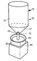
- FIG. 1 illustrates a side perspective view of the present invention, animal feeder
- FIG. 2 is a top exploded view of spinner assembly.
- FIG. 3 is an alternative embodiment of spinner assembly.
- FIG. 4 is an alternative embodiment of spinner assembly.
- FIG. 5 is an exploded view of cover member.
- FIG. 6 is a top view of the spinner plate with fins.
- FIG. 7 is cross-sectional view of spinner plate.
- an automatic animal feeder 10
- Barrel ( 20 ) is generally, a free-standing large container for storing the feed. Barrel ( 20 ) is surrounded by an upright circular base wall ( 25 ) with a bottom that forms funnel ( 27 ). Funnel ( 27 ) has a cone shape with opening ( 29 ) at the apex point. Funnel 27 conducts the feed through the opening ( 29 ) into spinner plate ( 40 ).
- spinner assembly 70 further comprises rod 75 centrally, perpendicularly and rigidly mounted upon the topside of base 80 .
- rod 75 extends vertically upward along the central axis to a predetermined distance into opening 29 of funnel 27 .
- bore 77 is disposed within base 80 extending vertically upward along the central axis of base 80 from the under side of base 80 to a predetermined distance within base 80 .
- Spinner plate ( 40 ) is circular in the preferred embodiment with surrounding upright walls ( 43 ) extending a short distance upward. As shown in FIG. 7 , disposed within the center of spinner plate 40 is aperture 41 for receiving rod 75 therethrough as shown in FIG. 1 .
- elongated shaft ( 45 ) is fixably mounted upon the top of control unit ( 60 ) and extends vertically upward through spinner plate ( 40 ) and into the bore 77 of base 80 .
- On one side of base 80 is a set screw 82 which extends horizontally therefrom into bore 77 .
- Set screw 82 is adapted to secure shaft 45 within bore 77 of base 80 .
- bore 77 is adapted with internal threads.
- shaft 45 is adapted with mating threads for engagement with the internal threads within bore 77 .
- the upright wall ( 43 ) of spinner plate ( 40 ) can flare outward in an arc, alternatively at an obtuse angle or alternatively at a right angle.
- Upright wall ( 43 ) extends a predetermined distance approximately below the height of the funnel ( 27 ). This configuration allows the rate and amount of flow of feed through the opening ( 29 ) of the funnel ( 27 ) as the spinner plate ( 40 ) rotates in conjunction with shaft ( 45 ).
- spinner plate 40 can be adapted with a plurality of spaced apart fins ( 85 ) circumferentially surrounding the peripheral edge ( 46 ) of spinner plate 40 .
- Each fin ( 85 ) extends vertically upward to a predetermined distance below funnel ( 27 ).
- Control unit ( 60 ) incorporates a conventional motor disposed below spinner plate ( 40 ).
- Control unit ( 60 ) can be adapted with a conventional timer for automatically setting the time for the elongated shaft ( 45 ) to rotate.
- the conventional timer is set to rotate periodic throughout the day.
- Control unit ( 60 ) can be adapted with a switch having control settings for controlling the movement of elongated shaft 45 .
- the elongated shaft ( 45 ) can be adapted to rotate 360 degrees at a predetermined rate, can be adapted to pivot back/forth, can be adapted to move up/down or a combination thereof.
- the rate of movement of the elongated shaft ( 45 ) can be adjusted relative to the stirring rate of the feed within the funnel ( 27 ).
- shaft ( 45 ) can be geared to rotate at different speeds through switch ( 64 ) of control unit ( 60 ).
- the tip of the elongated rod ( 75 ) can be adapted with a plurality of spaced stirring spikes ( 87 ) or at least one.
- Each spike ( 87 ) is mounted to the external surface of elongated rod ( 75 ) not shown and protruded outwardly a short distance therefrom.
- the tip of the elongated rod ( 75 ) or the entire surface area of elongated rod ( 75 ) can be embedded with recesses forming a helical shape stirrer ( 90 ). With each rotation of elongated rod ( 75 ), helical shape stirrer ( 90 ) provides the capability of metering an exact amount of feed into spinner plate ( 40 ).
- both stirrer ( 90 ) and spikes ( 87 ) can be affixed to rod ( 75 ).
- the base ( 119 ) of rod ( 75 ) extends underneath rod ( 75 ).
- stirrer spikes 87 and/or helical shape stirrer spike 90 can be affixed to cover 100 .
- cover 100 comprises base 110 with a centrally located hollow shaft member 115 extending linearly upward therefrom.
- Hollow shaft member 115 is adapted to engage with elongated rod 75 shown in FIG. 2 .
- hollow shaft member 115 is slidably engaged with elongated rod 75 .
- hollow shaft member 115 is engaged with elongated rod 75 .
- hollow shaft member 115 in conjunction with elongated rod 75 extends into the opening 29 of the funnel 27 as shown in FIG. 1 .
Landscapes
- Life Sciences & Earth Sciences (AREA)
- Environmental Sciences (AREA)
- Birds (AREA)
- Animal Husbandry (AREA)
- Biodiversity & Conservation Biology (AREA)
- Feeding And Watering For Cattle Raising And Animal Husbandry (AREA)
Abstract
Description
Claims (7)
Priority Applications (1)
| Application Number | Priority Date | Filing Date | Title |
|---|---|---|---|
| US12/154,771 US7954454B2 (en) | 2007-11-13 | 2008-05-27 | Sure feed automatic feeder |
Applications Claiming Priority (2)
| Application Number | Priority Date | Filing Date | Title |
|---|---|---|---|
| US255607P | 2007-11-13 | 2007-11-13 | |
| US12/154,771 US7954454B2 (en) | 2007-11-13 | 2008-05-27 | Sure feed automatic feeder |
Publications (2)
| Publication Number | Publication Date |
|---|---|
| US20090120369A1 US20090120369A1 (en) | 2009-05-14 |
| US7954454B2 true US7954454B2 (en) | 2011-06-07 |
Family
ID=40622521
Family Applications (1)
| Application Number | Title | Priority Date | Filing Date |
|---|---|---|---|
| US12/154,771 Expired - Fee Related US7954454B2 (en) | 2007-11-13 | 2008-05-27 | Sure feed automatic feeder |
Country Status (1)
| Country | Link |
|---|---|
| US (1) | US7954454B2 (en) |
Cited By (5)
| Publication number | Priority date | Publication date | Assignee | Title |
|---|---|---|---|---|
| US20100307421A1 (en) * | 2009-06-05 | 2010-12-09 | All Seasons Feeders, Inc. | Dual hopper animal feeder device |
| US9380740B2 (en) | 2013-11-18 | 2016-07-05 | Spreader Technology | Electric handheld broadcast spreader |
| US9491939B2 (en) | 2014-05-22 | 2016-11-15 | Anthony Myers | Top motor broadcast spreader apparatus |
| US20190075718A1 (en) * | 2016-03-09 | 2019-03-14 | Rauch Landmaschinenfabrik Gmbh | Distribution machine |
| US10842127B2 (en) | 2017-05-03 | 2020-11-24 | DeerRoots, LLC | Animal feeding system |
Families Citing this family (8)
| Publication number | Priority date | Publication date | Assignee | Title |
|---|---|---|---|---|
| US8689737B2 (en) | 2008-10-30 | 2014-04-08 | All Seasons Feeders, Inc. | Wildlife feeder |
| US9462783B2 (en) | 2008-10-30 | 2016-10-11 | All Seasons Feeders, Ltd. | Passive animal feeder having feed troughs |
| US9204619B2 (en) | 2008-10-30 | 2015-12-08 | All Seasons Feeders, Ltd. | Passive animal feeder having feed troughs including a tray portion |
| US20110088627A1 (en) * | 2009-10-20 | 2011-04-21 | All Seasons Feeders, Inc. | Integral control box, spinner and funnel unit with adjustable legs |
| US9101126B2 (en) * | 2010-01-11 | 2015-08-11 | Jager Pro, Llc | Remote control gate release for trap enclosure |
| TWI616135B (en) * | 2017-01-19 | 2018-03-01 | 宏碁股份有限公司 | Pet feeding device |
| US10810527B2 (en) * | 2017-04-14 | 2020-10-20 | Solunartek, LLC | Systems and methods for scheduling dispensing deer feed based on predicted periods of deer activity |
| USD882186S1 (en) * | 2018-12-18 | 2020-04-21 | Zaxe Technologies Inc. | Automatic animal feeder |
Citations (10)
| Publication number | Priority date | Publication date | Assignee | Title |
|---|---|---|---|---|
| US1355399A (en) * | 1918-02-26 | 1920-10-12 | Kelley George | Poultry-feeding appliance |
| US1359691A (en) * | 1920-11-23 | Automatic poultry-feeder | ||
| US1801787A (en) * | 1928-01-13 | 1931-04-21 | Zehner Christian | Apparatus for feeding fowl |
| US2967056A (en) * | 1955-10-28 | 1961-01-03 | Seaman Andwall Corp | Material spreaders for dump trucks |
| US3195508A (en) * | 1963-07-11 | 1965-07-20 | Charles L Lehman | Game and stock feeder |
| US4497446A (en) * | 1981-08-21 | 1985-02-05 | C. Van Der Lely N.V. | Spreader |
| US4986220A (en) * | 1990-04-10 | 1991-01-22 | Reneau Charles F | Game feeder and improved distributor |
| US5820035A (en) * | 1996-04-04 | 1998-10-13 | Johnson; John B. | Broadcast spreader mechanism |
| US20070014642A1 (en) * | 2005-02-02 | 2007-01-18 | Cristian Teodorescu | Automatic seeds or pellets feeder |
| US7222583B2 (en) * | 2004-04-28 | 2007-05-29 | Texas Hunter Products | Directional broadcast feeder for fish and game |
-
2008
- 2008-05-27 US US12/154,771 patent/US7954454B2/en not_active Expired - Fee Related
Patent Citations (10)
| Publication number | Priority date | Publication date | Assignee | Title |
|---|---|---|---|---|
| US1359691A (en) * | 1920-11-23 | Automatic poultry-feeder | ||
| US1355399A (en) * | 1918-02-26 | 1920-10-12 | Kelley George | Poultry-feeding appliance |
| US1801787A (en) * | 1928-01-13 | 1931-04-21 | Zehner Christian | Apparatus for feeding fowl |
| US2967056A (en) * | 1955-10-28 | 1961-01-03 | Seaman Andwall Corp | Material spreaders for dump trucks |
| US3195508A (en) * | 1963-07-11 | 1965-07-20 | Charles L Lehman | Game and stock feeder |
| US4497446A (en) * | 1981-08-21 | 1985-02-05 | C. Van Der Lely N.V. | Spreader |
| US4986220A (en) * | 1990-04-10 | 1991-01-22 | Reneau Charles F | Game feeder and improved distributor |
| US5820035A (en) * | 1996-04-04 | 1998-10-13 | Johnson; John B. | Broadcast spreader mechanism |
| US7222583B2 (en) * | 2004-04-28 | 2007-05-29 | Texas Hunter Products | Directional broadcast feeder for fish and game |
| US20070014642A1 (en) * | 2005-02-02 | 2007-01-18 | Cristian Teodorescu | Automatic seeds or pellets feeder |
Cited By (7)
| Publication number | Priority date | Publication date | Assignee | Title |
|---|---|---|---|---|
| US20100307421A1 (en) * | 2009-06-05 | 2010-12-09 | All Seasons Feeders, Inc. | Dual hopper animal feeder device |
| US8573156B2 (en) * | 2009-06-05 | 2013-11-05 | All Seasons Feeders, Inc. | Dual hopper animal feeder device |
| US9380740B2 (en) | 2013-11-18 | 2016-07-05 | Spreader Technology | Electric handheld broadcast spreader |
| US9491939B2 (en) | 2014-05-22 | 2016-11-15 | Anthony Myers | Top motor broadcast spreader apparatus |
| US20190075718A1 (en) * | 2016-03-09 | 2019-03-14 | Rauch Landmaschinenfabrik Gmbh | Distribution machine |
| US11116128B2 (en) * | 2016-03-09 | 2021-09-14 | Rauch Landmaschinenfabrik Gmbh | Distribution machine |
| US10842127B2 (en) | 2017-05-03 | 2020-11-24 | DeerRoots, LLC | Animal feeding system |
Also Published As
| Publication number | Publication date |
|---|---|
| US20090120369A1 (en) | 2009-05-14 |
Similar Documents
| Publication | Publication Date | Title |
|---|---|---|
| US7954454B2 (en) | Sure feed automatic feeder | |
| US10299465B2 (en) | Oriole jelly birdfeeder | |
| US4719875A (en) | Hog feeder with flexible agitator | |
| US7798098B1 (en) | Animal feeder | |
| US20080276873A1 (en) | Animal Feeder Device | |
| US7753000B1 (en) | Controlled hay feeder | |
| US5957082A (en) | Rotatable food dispenser | |
| KR101067843B1 (en) | Swine automatic wet feeder and its use | |
| EP3275310B1 (en) | Baffle for an animal feeding device | |
| US8833303B1 (en) | Pellet dispersing blade assembly | |
| KR200443101Y1 (en) | Wet Pig Feed Feeder | |
| KR200448419Y1 (en) | Feed and drinking water supply system of livestock feeder | |
| US12490715B1 (en) | Broadcast feeder | |
| US11730140B2 (en) | Game feeder | |
| KR200441755Y1 (en) | Basin dosing control system | |
| JP3139369U (en) | Feed spraying device | |
| TWM460531U (en) | Multiple-fixed-point automatic feedstuff throwing feeding device | |
| EP1716750A1 (en) | A livestock feeding assembly | |
| KR102012081B1 (en) | Liquid feed grade excitation | |
| KR200316988Y1 (en) | The feeder for pig breeding | |
| US20230363351A1 (en) | Game feeder | |
| KR20040110118A (en) | An food automatic surplus equipment of one's pet. | |
| KR20080011625A (en) | Livestock Feeder | |
| KR102523241B1 (en) | Poultry feedder | |
| RU28950U1 (en) | Automatic feeder, especially for pigs |
Legal Events
| Date | Code | Title | Description |
|---|---|---|---|
| FEPP | Fee payment procedure |
Free format text: PETITION RELATED TO MAINTENANCE FEES FILED (ORIGINAL EVENT CODE: PMFP); ENTITY STATUS OF PATENT OWNER: MICROENTITY |
|
| REMI | Maintenance fee reminder mailed | ||
| LAPS | Lapse for failure to pay maintenance fees | ||
| REIN | Reinstatement after maintenance fee payment confirmed | ||
| FP | Lapsed due to failure to pay maintenance fee |
Effective date: 20150607 |
|
| FPAY | Fee payment |
Year of fee payment: 4 |
|
| SULP | Surcharge for late payment | ||
| FEPP | Fee payment procedure |
Free format text: PETITION RELATED TO MAINTENANCE FEES GRANTED (ORIGINAL EVENT CODE: PMFG); ENTITY STATUS OF PATENT OWNER: MICROENTITY |
|
| PRDP | Patent reinstated due to the acceptance of a late maintenance fee |
Effective date: 20160418 |
|
| STCF | Information on status: patent grant |
Free format text: PATENTED CASE |
|
| FEPP | Fee payment procedure |
Free format text: MAINTENANCE FEE REMINDER MAILED (ORIGINAL EVENT CODE: REM.); ENTITY STATUS OF PATENT OWNER: MICROENTITY |
|
| LAPS | Lapse for failure to pay maintenance fees |
Free format text: PATENT EXPIRED FOR FAILURE TO PAY MAINTENANCE FEES (ORIGINAL EVENT CODE: EXP.); ENTITY STATUS OF PATENT OWNER: MICROENTITY |
|
| STCH | Information on status: patent discontinuation |
Free format text: PATENT EXPIRED DUE TO NONPAYMENT OF MAINTENANCE FEES UNDER 37 CFR 1.362 |
|
| FP | Lapsed due to failure to pay maintenance fee |
Effective date: 20190607 |