US7940971B2 - System and method for coronary digital subtraction angiography - Google Patents
System and method for coronary digital subtraction angiography Download PDFInfo
- Publication number
- US7940971B2 US7940971B2 US11/779,405 US77940507A US7940971B2 US 7940971 B2 US7940971 B2 US 7940971B2 US 77940507 A US77940507 A US 77940507A US 7940971 B2 US7940971 B2 US 7940971B2
- Authority
- US
- United States
- Prior art keywords
- image
- sequence
- objects
- fluoroscopic images
- motion
- Prior art date
- Legal status (The legal status is an assumption and is not a legal conclusion. Google has not performed a legal analysis and makes no representation as to the accuracy of the status listed.)
- Expired - Fee Related, expires
Links
Images


Classifications
-
- G—PHYSICS
- G06—COMPUTING OR CALCULATING; COUNTING
- G06V—IMAGE OR VIDEO RECOGNITION OR UNDERSTANDING
- G06V10/00—Arrangements for image or video recognition or understanding
- G06V10/20—Image preprocessing
- G06V10/26—Segmentation of patterns in the image field; Cutting or merging of image elements to establish the pattern region, e.g. clustering-based techniques; Detection of occlusion
-
- G—PHYSICS
- G06—COMPUTING OR CALCULATING; COUNTING
- G06V—IMAGE OR VIDEO RECOGNITION OR UNDERSTANDING
- G06V2201/00—Indexing scheme relating to image or video recognition or understanding
- G06V2201/03—Recognition of patterns in medical or anatomical images
-
- Y—GENERAL TAGGING OF NEW TECHNOLOGICAL DEVELOPMENTS; GENERAL TAGGING OF CROSS-SECTIONAL TECHNOLOGIES SPANNING OVER SEVERAL SECTIONS OF THE IPC; TECHNICAL SUBJECTS COVERED BY FORMER USPC CROSS-REFERENCE ART COLLECTIONS [XRACs] AND DIGESTS
- Y10—TECHNICAL SUBJECTS COVERED BY FORMER USPC
- Y10S—TECHNICAL SUBJECTS COVERED BY FORMER USPC CROSS-REFERENCE ART COLLECTIONS [XRACs] AND DIGESTS
- Y10S128/00—Surgery
- Y10S128/92—Computer assisted medical diagnostics
- Y10S128/922—Computer assisted medical diagnostics including image analysis
Definitions
- the present invention relates to fluoroscopic image sequences, and more particularly to extracting motion-based layers from fluoroscopic image sequences.
- Angiography is a medical imaging technique in which X-ray images are used to visualize internal blood filled structures, such as arteries, veins, and the heart chambers. Since blood has the same radiodensity as the surrounding tissues, these blood filled structures cannot be differentiated from the surrounding tissue using conventional radiology. Thus, in angiography, a contrast agent is added to the blood, usually via a catheter, to make the blood vessels visible via X-ray. In many angiography procedures, X-ray images are taken over a period of time, which results in a sequence of fluoroscopic images, which show the motion of the blood over the period of time. Such fluoroscopic image sequences contain useful information that can be difficult to decipher due to the collapsing of 3-dimensional information into the 2-dimensional images.
- the present invention provides a method and system for extracting motion-based layers from fluoroscopic image sequences. Different objects in a fluoroscopic image sequence have different patterns of motion. Embodiments of the present invention utilize this fact to extract objects from a fluoroscopic image sequence in layers based on the motion patterns found in the fluoroscopic image sequence.
- portions of multiple objects are detected in a sequence of fluoroscopic images. Motion of the detected portions of the objects is estimated between the consecutive images in the sequence of fluoroscopic images. The images in the sequence of fluoroscopic images are then divided into multiple layers based on the estimated motion of the detected portions of the multiple objects.
- the coronary tree and the diaphragm are detected in frames of a coronary angiograph fluoroscopic image sequence.
- Motion vectors are calculated for the diaphragm and the vessel tree between consecutive frames of the fluoroscopic image sequence.
- a thin-plate spline model is used to extrapolate motion fields over the entire frame based on the motion vectors, and least squares estimation is used to extract the vessel tree and diaphragm in separate layers based on the motion fields.
- FIG. 1 illustrates the separation of layers of a fluoroscopic image based on relative motion
- FIG. 2 illustrates a method of extracting motion-based layers from a sequence of fluoroscopic images according to an embodiment of the present invention
- FIG. 3 illustrates a coronary digital subtraction angiography method according to an embodiment of the present invention
- FIG. 4 illustrates detection of the diaphragm and the vessel tree in a frame of a fluoroscopic image sequence
- FIG. 5 illustrates estimation of motion of the diaphragm and the vessel tree between consecutive frames in a fluoroscopic image sequence
- FIG. 6 illustrates extrapolated motion fields for a frame in the fluoroscopic image sequence based on motion vectors for the diaphragm and the vessel tree;
- FIG. 7 illustrates removal of background from an image
- FIGS. 8A and 8B illustrate exemplary motion-based layers resulting from implementing the method of FIG. 3 ;
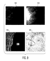
- FIG. 9 illustrates exemplary motion-based layers which separate a guidewire from a lung in a sequence of fluoroscopic images.
- FIG. 10 is a high level block diagram of a computer capable of implementing the present invention.
- the present invention is directed to a method for extracting motion-based layers from fluoroscopic images.
- Embodiments of the present invention are described herein to give a visual understanding of the motion layer extraction method.
- a digital image is often composed of digital representations of one or more objects (or shapes).
- the digital representation of an object is often described herein in terms of identifying and manipulating the objects.
- Such manipulations are virtual manipulations accomplished in the memory or other circuitry/hardware of a computer system. Accordingly, is to be understood that embodiments of the present invention may be performed within a computer system using data stored within the computer system.
- a sequence of fluoroscopic images contains multiple X-ray images obtained in real time.
- the X-ray images record a certain field of view of a time period. Accordingly, motion of objects within the field of view can be observed in a sequence of fluoroscopic images.
- different objects e.g. heart lungs, bones, etc.
- the motion of the heart is faster than that of the lungs.
- the bones and spine usually remain static throughout a sequence of fluoroscopic images.
- a fluoroscopic image 100 can be separated into three layers based on the relative motion of the layers (fast, slow, static). Since the motion of the heart 102 is faster than that of the lungs 104 , the heart 102 and coronary tree can be separated from the rest of the image 100 by the fast movement layer. Similarly, the lungs 104 can be separated from the rest of the image 100 by the slow movement layer. Static objects such as the spine 106 , as well as background, can be separated from the image 100 the static layer. It is to be understood that the heart 102 , lungs 104 , and spine 106 shown in FIG. 1 are representative of objects that can be extracted using the motion-based layers separation framework.
- FIG. 2 illustrates a method of extracting motion-based layers from a sequence of fluoroscopic images according to an embodiment of the present invention.
- a sequence of fluoroscopic images is received.
- the sequence of fluoroscopic images can be electronic data representing images resulting from an X-ray procedure, such as an angiograph.
- the sequence of fluoroscopic images are images of a region taken at a regular interval over a time frame. Each image in the sequence can be referred to as a frame.
- each of multiple objects is detected in the sequence of fluoroscopic images.
- the objects may be anatomical structures such as the heart, the lungs, the diaphragm, the vessel tree, etc.
- the objects may also be non-anatomical objects such as a stent or guidewire.
- the objects may be detected manually, by a user annotating the fluoroscopic images, however, in an advantageous embodiment of the present invention, the objects are detected automatically. For example, the objects may be detected automatically using learning-based detection methods.
- motion is estimated for the detected portions of each of the multiple objects in the sequence of fluoroscopic images.
- the motion can be estimated for an object in the sequence of images by obtaining motion vectors between consecutive frames of the sequence of fluoroscopic images.
- the motion vectors may be obtained manually by a user annotating an object in consecutive frames, however, in a preferred embodiment of the present invention, the motion vectors are obtained automatically.
- the motion vectors may be obtained using learning based tracking methods to track the detected portions of the objects between consecutive frames. It is possible to represent the motion estimated for each object using a thin-plate spline model.
- multiple image layers are extracted from the sequence of fluoroscopic images based on the motion estimated for each of the detected objects.
- Each motion-based layer includes a sequence of images corresponding to portions of the original sequence of fluoroscopic images having similar relative motion.
- the motion-based layers can be extracted from the sequence of fluoroscopic images using a least square estimation problem.
- the image layers are estimated for each frame using motion information of multiple frames. For example, 9 frames including the current frame, the previous 4 frames, and the following 4 frames can be used to estimate the image layers for a frame. It is to be understood, that this number of frames is exemplary, and various embodiments of the present invention may utilize the motion information from more or less frames.
- images of the same layer can be used to form a video (sequence of images) of that layer.
- a video of a single layer can be used to observe motion of a specific anatomical structure in that layer, such as a video which contains only the coronary vessel tree.
- FIG. 3 illustrates an embodiment of the present invention in which the method of FIG. 2 is used to extract the coronary tree (vessel tree) from a fluoroscopic image sequence resulting from a coronary angiography.
- the method shown in FIG. 3 can be referred to as coronary Digital Subtraction Angiography (DSA).
- DSA coronary Digital Subtraction Angiography
- a fluoroscopic image sequence 302 including multiple frames is received.
- portions of the vessel tree and the diaphragm are detected in each frame of the fluoroscopic image sequence.
- a learning-based detection method can be used to automatically detected the medial axes of the vessels and the boundary of the diaphragm.
- the vessel segmentation can be performed by discriminating patterns in the joint 2D-temporal domains. This may employ learning algorithms such as marginal space learning and probabilistic boosting tree, but the present invention is not restricted thereto.
- Marginal space learning is described in detail in Adrian et al., “Hierarchical Learning of Curves: Application to Guidewire Localization in Fluoroscopy”, IEEE International Conference on Computer Vision and Pattern Recognition, Minneapolis, Minn., 2007, which is incorporated herein by reference.
- Probabilistic boosting tree is described in detail in Zhuowen et al., “Probabilistic Boosting-Tree: Learning Discriminative Models for Classification, Recognition, and Clustering”, IEEE International Conference on Computer Vision, Beijing, China, 2006, which is incorporated herein by reference.
- FIG. 4 illustrates the detection of the boundary of the diaphragm and the medial axes of the vessels in a frame of the fluoroscopic image sequence.
- Image 410 of FIG. 4 shows the detected boundary 412 of the diaphragm
- image 420 of FIG. 4 shows the detected medial axes 422 of the vessels.
- the medial axes 422 of the vessels can be represented by splines.
- the transparent motion is estimated for the vessel tree and the diaphragm.
- a learning based tracking method can be used to track the detected portions of the vessel tree and the diaphragm between consecutive frames in order to obtain motion vectors showing the motion of the vessel tree and the diaphragm between consecutive frames.
- the vessel tree can be represented by the tree junctions and the vessel endpoints. These are tracked and new junctions and endpoints are connected to the tree as the contrast is injected. From the junction trajectories, a consistent tree is reconstructed and its motion can be estimated.
- FIG. 5 illustrates the estimation of the motion of the diaphragm and the vessel tree between consecutive frames in the fluoroscopic image sequence. Image 510 of FIG.
- Image 5 illustrates motion vectors 516 showing the motion between a first boundary 512 of the diaphragm and a second boundary 514 of the diaphragm detected in consecutive frames.
- Image 520 illustrates motion vectors 526 showing the motion between a first detected vessel tree 522 and a second detected vessel tree 524 detected in consecutive frames.
- a thin-plate spline model is computed based on the motion vectors obtained for the detected portions of the objects to extrapolate the motion fields over the whole image.
- FIG. 6 illustrates the extrapolated motion fields for an image (frame) in the fluoroscopic image sequence based on the motion vectors for the diaphragm and the vessel tree.
- Image 610 of FIG. 6 illustrates the motion field extrapolated based on the estimated motion of the diaphragm
- image 620 of FIG. 6 illustrates the motion field extrapolated based on the estimated motion of the vessel tree.
- Thin-plate spline models are widely used as non-rigid transformation models for image alignment and shaped matching.
- thin-plate spline refers to a physical analogy involving the bending of a thin sheet of metal. In the physical setting, the deflection is in the z direction, orthogonal to the plane. When applied the idea to the problem of coordinate transformation, one interprets the lifting of the plate as a displacement of the x or y coordinates within the plane.
- One advantage of using a thin-plate spline model to represent motion in the image is that the motion field is smooth with derivatives of any order.
- Another advantage of the thin-plate spline is that it can always be decomposed into a global affine and a local non-affine component.
- step 310 least squares estimation is used to extract layers of the fluoroscopic image sequence based on the motion fields estimated by the thin-plate spline models resulting in motion based layers 312 , which can be output, displayed, stored, etc.
- the layer extraction problem is to extract layers from a fluoroscopic image sequence which consists of N layers with uniform transparency, i.e., the contribution of each layer to the image is 1/N.
- N x N 0 e ⁇ x .
- This equation holds in the ideal case when the sum of all layers is exactly equal to the observed image. In practice, this equation is an approximation because of image noise and local deformation.
- M images (frames) in a sequence can be used to find a least squares solution that minimizes the reconstruction error for the N layers, where M>N.
- the least squares solution can be expressed as:
- the least squares problem can be very large in scale. If the width of the image is W and the height of the image is H, then the number of unknowns in the least squares problem is WHN, while the number of equations is WHM. For example, to estimate 3 layers for a sequence with image size 256 ⁇ 256, the number of unknowns is 196608. However, the transformation matrix T l m is very sparse, with most of its entries having the value of zero. Accordingly, this least squares problem can be solved using an iterative optimization technique.
- this least squares problem is actually a constrained optimization problem.
- the method of FIG. 3 shows detecting the diaphragm and the vessel tree and extracting layers based on the movement thereof. It is to be understood that portions of the background of the image can also be detected so that a static layer of the image sequence can be extracted. It is also possible, according to an embodiment of the present invention, that the background can be estimated prior to detecting the various objects in the image sequence. Based on the assumption that the background does not change in the image sequence, the estimated background can then be removed from the image sequence prior to detecting the diaphragm and the vessel tree. In this way, the problem complexity can be reduced (i.e., two unknown layers instead of three). This can be implemented as a coarse to fine approach in which all the layers are estimated roughly and greater emphasis given to the moving layers. FIG.
- Image 702 shows an original image or frame of a fluoroscopic image sequence
- image 704 shows the background which is removed from image 702
- image 706 shows the resultant image once the background 704 is removed from image 702 .
- FIGS. 8A and 8B show exemplary motion-based layers resulting from an implementation of the method of FIG. 3 .
- images 802 and 804 show frames from a sequence of fluoroscopic images.
- Images 804 and 814 show background layers of images 802 and 812 , respectively, including static objects such as bones.
- Images 806 and 816 show slow moving layers of images 802 and 812 , respectively, including the diaphragm.
- Images 808 and 818 show fast moving layers of images 802 and 812 , respectively, including the vessel tree. As illustrated in FIG. 8 , the vessel tree is much more visible in images 808 and 818 than in the original fluoroscopic images 802 and 812 .
- FIG. 9 illustrates exemplary motion-based layers which separate a guidewire from a lung in a sequence of fluoroscopic images.
- image 902 shows a fluoroscopic image from a sequence of fluoroscopic images.
- Image 904 illustrates a background layer (static layer) extracted from image 902 .
- Image 906 illustrates a motion-based layer which clearly shows the lung 907 .
- Image 908 illustrates a motion-based layer which clearly shows the guidewire 909 .
- the guidewire is difficult to see in image 902 , but can be clearly seen in image 908 .
- One advantageous use of the methods described above is for coronary enhancement. This is especially beneficial in severely obese patients. In such patients, cardiologists often can ‘barely see anything’, especially with extreme angulations where the radiation has a long way through the body.
- the above described methods can also help to save contrast medium used in angiography procedures by overlaying a previously extracted coronary motion layer containing the contrast-filled coronaries with the contrastless frames. Also, the above described methods can detect coronaries that got a diluted contrast medium. Furthermore, the methods described above can also be used to improve stent visibility in fluoroscopic images.
- Computer 1002 contains a processor 1004 which controls the overall operation of the computer 1002 by executing computer program instructions which define such operation.
- the computer program instructions may be stored in a storage device 1012 (e.g., magnetic disk) and loaded into memory 1010 when execution of the computer program instructions is desired.
- the computer 1002 also includes one or more network interfaces 1006 for communicating with other devices via a network.
- the computer 1002 also includes other input/output devices 1008 that enable user interaction with the computer 1002 (e.g., display, keyboard, mouse, speakers, buttons, etc.)
- FIG. 10 is a high level representation of some of the components of such a computer for illustrative purposes.
Landscapes
- Engineering & Computer Science (AREA)
- Physics & Mathematics (AREA)
- General Physics & Mathematics (AREA)
- Multimedia (AREA)
- Theoretical Computer Science (AREA)
- Apparatus For Radiation Diagnosis (AREA)
- Image Analysis (AREA)
Abstract
Description
Nx=N0eμx.
After passing through multiple layers of materials, the final amount of photon fluence received by a detector which generates the X-ray image is:
N=N0eΣμ
where Im is the mth observed image (frame) in a sequence, Ll is the lth layer (unknown), and Tl m is the transformation which maps the lth layer to the mth image according to the motion information. This equation holds in the ideal case when the sum of all layers is exactly equal to the observed image. In practice, this equation is an approximation because of image noise and local deformation.
Claims (28)
Priority Applications (1)
| Application Number | Priority Date | Filing Date | Title |
|---|---|---|---|
| US11/779,405 US7940971B2 (en) | 2006-07-24 | 2007-07-18 | System and method for coronary digital subtraction angiography |
Applications Claiming Priority (3)
| Application Number | Priority Date | Filing Date | Title |
|---|---|---|---|
| US82014406P | 2006-07-24 | 2006-07-24 | |
| US94673807P | 2007-06-28 | 2007-06-28 | |
| US11/779,405 US7940971B2 (en) | 2006-07-24 | 2007-07-18 | System and method for coronary digital subtraction angiography |
Publications (2)
| Publication Number | Publication Date |
|---|---|
| US20080025588A1 US20080025588A1 (en) | 2008-01-31 |
| US7940971B2 true US7940971B2 (en) | 2011-05-10 |
Family
ID=38986355
Family Applications (1)
| Application Number | Title | Priority Date | Filing Date |
|---|---|---|---|
| US11/779,405 Expired - Fee Related US7940971B2 (en) | 2006-07-24 | 2007-07-18 | System and method for coronary digital subtraction angiography |
Country Status (1)
| Country | Link |
|---|---|
| US (1) | US7940971B2 (en) |
Cited By (4)
| Publication number | Priority date | Publication date | Assignee | Title |
|---|---|---|---|---|
| US20090010512A1 (en) * | 2007-06-28 | 2009-01-08 | Ying Zhu | System and method for coronary digital subtraction angiography |
| US20100034446A1 (en) * | 2008-08-06 | 2010-02-11 | Siemens Corporate Research,Inc. | System and Method for Coronary Digital Subtraction Angiography |
| US20120123250A1 (en) * | 2010-11-16 | 2012-05-17 | Siemens Aktiengesellschaft | Method and System for Pigtail Catheter Motion Prediction |
| US8638999B2 (en) * | 2012-04-16 | 2014-01-28 | General Electric Company | Methods for generating a reconstructed tree structure from medical image data |
Families Citing this family (26)
| Publication number | Priority date | Publication date | Assignee | Title |
|---|---|---|---|---|
| US20100014726A1 (en) * | 2006-06-01 | 2010-01-21 | Koninklijke Philips Electronics N.V. | Hierarchical motion estimation |
| US7940971B2 (en) * | 2006-07-24 | 2011-05-10 | Siemens Medical Solutions Usa, Inc. | System and method for coronary digital subtraction angiography |
| US20080178087A1 (en) * | 2007-01-19 | 2008-07-24 | Microsoft Corporation | In-Scene Editing of Image Sequences |
| US8355557B2 (en) * | 2008-10-10 | 2013-01-15 | Siemens Aktiengesellschaft | System and method for decomposed temporal filtering for X-ray guided intervention application |
| US8355551B2 (en) * | 2009-02-27 | 2013-01-15 | General Electric Company | Method and apparatus for reducing image artifacts |
| US8675914B2 (en) * | 2009-09-14 | 2014-03-18 | Siemens Aktiengesellschaft | Method and system for needle tracking in fluoroscopic image sequences |
| US8605969B2 (en) | 2010-04-06 | 2013-12-10 | Siemens Corporation | Method and system for multiple object detection by sequential Monte Carlo and hierarchical detection network |
| DE102010026675B4 (en) * | 2010-07-09 | 2019-07-25 | Siemens Healthcare Gmbh | Method and device for determining a phase of an object movement in an image series, imaging device and computer program product |
| US10682112B2 (en) * | 2013-11-20 | 2020-06-16 | Koninklijke Philips N.V. | Suppression of independent movements in a series of 2D X-ray fluoroscopy images using a 3D pre-operative volume |
| US10726593B2 (en) * | 2015-09-22 | 2020-07-28 | Fyusion, Inc. | Artificially rendering images using viewpoint interpolation and extrapolation |
| KR20160089976A (en) | 2015-01-21 | 2016-07-29 | 삼성전자주식회사 | X-ray imaging apparatus and control method for the same |
| US12495134B2 (en) | 2015-07-15 | 2025-12-09 | Fyusion, Inc. | Drone based capture of multi-view interactive digital media |
| US10147211B2 (en) | 2015-07-15 | 2018-12-04 | Fyusion, Inc. | Artificially rendering images using viewpoint interpolation and extrapolation |
| US11095869B2 (en) | 2015-09-22 | 2021-08-17 | Fyusion, Inc. | System and method for generating combined embedded multi-view interactive digital media representations |
| US12261990B2 (en) | 2015-07-15 | 2025-03-25 | Fyusion, Inc. | System and method for generating combined embedded multi-view interactive digital media representations |
| US10222932B2 (en) | 2015-07-15 | 2019-03-05 | Fyusion, Inc. | Virtual reality environment based manipulation of multilayered multi-view interactive digital media representations |
| US10242474B2 (en) | 2015-07-15 | 2019-03-26 | Fyusion, Inc. | Artificially rendering images using viewpoint interpolation and extrapolation |
| US11006095B2 (en) | 2015-07-15 | 2021-05-11 | Fyusion, Inc. | Drone based capture of a multi-view interactive digital media |
| US11783864B2 (en) | 2015-09-22 | 2023-10-10 | Fyusion, Inc. | Integration of audio into a multi-view interactive digital media representation |
| US11202017B2 (en) | 2016-10-06 | 2021-12-14 | Fyusion, Inc. | Live style transfer on a mobile device |
| US10437879B2 (en) | 2017-01-18 | 2019-10-08 | Fyusion, Inc. | Visual search using multi-view interactive digital media representations |
| US20180227482A1 (en) | 2017-02-07 | 2018-08-09 | Fyusion, Inc. | Scene-aware selection of filters and effects for visual digital media content |
| US10313651B2 (en) | 2017-05-22 | 2019-06-04 | Fyusion, Inc. | Snapshots at predefined intervals or angles |
| US11069147B2 (en) | 2017-06-26 | 2021-07-20 | Fyusion, Inc. | Modification of multi-view interactive digital media representation |
| US10592747B2 (en) | 2018-04-26 | 2020-03-17 | Fyusion, Inc. | Method and apparatus for 3-D auto tagging |
| WO2023030344A1 (en) * | 2021-08-30 | 2023-03-09 | Shanghai United Imaging Healthcare Co., Ltd. | Systems and methods for medical image processing |
Citations (9)
| Publication number | Priority date | Publication date | Assignee | Title |
|---|---|---|---|---|
| US4689670A (en) * | 1984-01-19 | 1987-08-25 | Kabushiki Kaisha Toshiba | Method and apparatus for measuring a biological function of a subject |
| US5557684A (en) * | 1993-03-15 | 1996-09-17 | Massachusetts Institute Of Technology | System for encoding image data into multiple layers representing regions of coherent motion and associated motion parameters |
| US5586201A (en) * | 1990-11-14 | 1996-12-17 | Cedars-Sinai Medical Center | Coronary tracking display |
| US6826292B1 (en) * | 2000-06-23 | 2004-11-30 | Sarnoff Corporation | Method and apparatus for tracking moving objects in a sequence of two-dimensional images using a dynamic layered representation |
| US6987865B1 (en) * | 2000-09-09 | 2006-01-17 | Microsoft Corp. | System and method for extracting reflection and transparency layers from multiple images |
| US20060285747A1 (en) * | 2005-06-17 | 2006-12-21 | Microsoft Corporation | Image segmentation |
| US20070116356A1 (en) * | 2005-10-27 | 2007-05-24 | Nec Laboratories America | Video foreground segmentation method |
| US20080025588A1 (en) * | 2006-07-24 | 2008-01-31 | Siemens Corporate Research, Inc. | System and Method For Coronary Digital Subtraction Angiography |
| US20100183196A1 (en) * | 2005-06-29 | 2010-07-22 | Accuray Incorporated | Dynamic tracking of soft tissue targets with ultrasound images, without using fiducial markers |
-
2007
- 2007-07-18 US US11/779,405 patent/US7940971B2/en not_active Expired - Fee Related
Patent Citations (10)
| Publication number | Priority date | Publication date | Assignee | Title |
|---|---|---|---|---|
| US4689670A (en) * | 1984-01-19 | 1987-08-25 | Kabushiki Kaisha Toshiba | Method and apparatus for measuring a biological function of a subject |
| US5586201A (en) * | 1990-11-14 | 1996-12-17 | Cedars-Sinai Medical Center | Coronary tracking display |
| US5557684A (en) * | 1993-03-15 | 1996-09-17 | Massachusetts Institute Of Technology | System for encoding image data into multiple layers representing regions of coherent motion and associated motion parameters |
| US6826292B1 (en) * | 2000-06-23 | 2004-11-30 | Sarnoff Corporation | Method and apparatus for tracking moving objects in a sequence of two-dimensional images using a dynamic layered representation |
| US6987865B1 (en) * | 2000-09-09 | 2006-01-17 | Microsoft Corp. | System and method for extracting reflection and transparency layers from multiple images |
| US7155032B2 (en) * | 2000-09-09 | 2006-12-26 | Microsoft Corp. | System and method for extracting reflection and transparency layers from multiple images |
| US20060285747A1 (en) * | 2005-06-17 | 2006-12-21 | Microsoft Corporation | Image segmentation |
| US20100183196A1 (en) * | 2005-06-29 | 2010-07-22 | Accuray Incorporated | Dynamic tracking of soft tissue targets with ultrasound images, without using fiducial markers |
| US20070116356A1 (en) * | 2005-10-27 | 2007-05-24 | Nec Laboratories America | Video foreground segmentation method |
| US20080025588A1 (en) * | 2006-07-24 | 2008-01-31 | Siemens Corporate Research, Inc. | System and Method For Coronary Digital Subtraction Angiography |
Non-Patent Citations (3)
| Title |
|---|
| Barbu, A. et al., "Hierarchical Learning of Curves Application to Guidewire Localization in Fluoroscopy," IEEE International Conference on Computer Vision and Pattern Recognition, Minneapolis, MN 2007. |
| Coleman, T. F. et al., "A Reflective Newton Method for Minimizing a Quadratic Function Subject to Bounds on some of the Variables," SIAM Journal on Optimization. Jun. 4, 1996. |
| Tu, Z, "Probabilistic Boosting-Tree, Learning Discriminative Models for Classification, Recognition, and Clustering," IEEE International Conference on Computer Vision, Beijing, China 2006. |
Cited By (7)
| Publication number | Priority date | Publication date | Assignee | Title |
|---|---|---|---|---|
| US20090010512A1 (en) * | 2007-06-28 | 2009-01-08 | Ying Zhu | System and method for coronary digital subtraction angiography |
| US8094903B2 (en) * | 2007-06-28 | 2012-01-10 | Siemens Aktiengesellschaft | System and method for coronary digital subtraction angiography |
| US20100034446A1 (en) * | 2008-08-06 | 2010-02-11 | Siemens Corporate Research,Inc. | System and Method for Coronary Digital Subtraction Angiography |
| US8345944B2 (en) * | 2008-08-06 | 2013-01-01 | Siemens Aktiengesellschaft | System and method for coronary digital subtraction angiography |
| US20120123250A1 (en) * | 2010-11-16 | 2012-05-17 | Siemens Aktiengesellschaft | Method and System for Pigtail Catheter Motion Prediction |
| US9999399B2 (en) * | 2010-11-16 | 2018-06-19 | Siemens Healthcare Gmbh | Method and system for pigtail catheter motion prediction |
| US8638999B2 (en) * | 2012-04-16 | 2014-01-28 | General Electric Company | Methods for generating a reconstructed tree structure from medical image data |
Also Published As
| Publication number | Publication date |
|---|---|
| US20080025588A1 (en) | 2008-01-31 |
Similar Documents
| Publication | Publication Date | Title |
|---|---|---|
| US7940971B2 (en) | System and method for coronary digital subtraction angiography | |
| US8345944B2 (en) | System and method for coronary digital subtraction angiography | |
| US8428319B2 (en) | Automatic measurement of morphometric and motion parameters of the coronary tree from a rotational X-ray sequence | |
| CN102715906B (en) | Method and system for 3D cardiac motion estimation from single scan of c-arm angiography | |
| Bentoutou et al. | An invariant approach for image registration in digital subtraction angiography | |
| US8798347B2 (en) | System and method for image-based respiratory motion compensation for fluoroscopic coronary roadmapping | |
| US9547894B2 (en) | Apparatus for, and method of, processing volumetric medical image data | |
| US8620050B2 (en) | System and method for 2-D/3-D registration between 3-D volume and 2-D angiography | |
| US8094903B2 (en) | System and method for coronary digital subtraction angiography | |
| Hansis et al. | Projection-based motion compensation for gated coronary artery reconstruction from rotational x-ray angiograms | |
| CN109791692A (en) | Computer aided detection is carried out using the multiple images of the different perspectives from area-of-interest to improve accuracy in detection | |
| US9524550B2 (en) | System and method for coronary digital subtraction angiography | |
| US11615267B2 (en) | X-ray image synthesis from CT images for training nodule detection systems | |
| CN107451995A (en) | Cardiovascular method, apparatus, equipment and storage medium are extracted in CTA images | |
| Meijering | Image enhancement in digital X-ray angiography | |
| Wen et al. | Enhanced coronary calcium visualization and detection from dual energy chest x-rays with sliding organ registration | |
| Zhang et al. | Vesselness-constrained robust PCA for vessel enhancement in x-ray coronary angiograms | |
| Slabaugh et al. | Variational guidewire tracking using phase congruency | |
| Cooke et al. | Fundamentals of image processing in nuclear medicine | |
| Zhang et al. | Coronary tree extraction using motion layer separation | |
| Preston et al. | Multi-layer deformation estimation for fluoroscopic imaging | |
| Leung et al. | Probabilistic framework for tracking in artifact-prone 3D echocardiograms | |
| Zhang et al. | Temporally diffeomorphic cardiac motion estimation from three‐dimensional echocardiography by minimization of intensity consistency error | |
| Wagner et al. | Feature-based respiratory motion tracking in native fluoroscopic sequences for dynamic roadmaps during minimally invasive procedures in the thorax and abdomen | |
| CN114463259B (en) | A method, device, equipment and storage medium for calculating dual-energy subtraction parameters |
Legal Events
| Date | Code | Title | Description |
|---|---|---|---|
| AS | Assignment |
Owner name: SIEMENS CORPORATE RESEARCH, INC., NEW JERSEY Free format text: ASSIGNMENT OF ASSIGNORS INTEREST;ASSIGNORS:ZHANG, WEI;BARBU, ADRIAN;REDDY, CHANDAN;AND OTHERS;REEL/FRAME:019981/0957;SIGNING DATES FROM 20070823 TO 20071009 Owner name: SIEMENS AKTIENGESELLSCHAFT, GERMANY Free format text: ASSIGNMENT OF ASSIGNORS INTEREST;ASSIGNORS:PRUMMER, SIMONE;OSTERMEIER, MARTIN;REEL/FRAME:019982/0005 Effective date: 20070829 Owner name: SIEMENS CORPORATE RESEARCH, INC., NEW JERSEY Free format text: ASSIGNMENT OF ASSIGNORS INTEREST;ASSIGNORS:ZHANG, WEI;BARBU, ADRIAN;REDDY, CHANDAN;AND OTHERS;SIGNING DATES FROM 20070823 TO 20071009;REEL/FRAME:019981/0957 |
|
| AS | Assignment |
Owner name: SIEMENS MEDICAL SOLUTIONS USA, INC., PENNSYLVANIA Free format text: ASSIGNMENT OF ASSIGNORS INTEREST;ASSIGNOR:SIEMENS CORPORATE RESEARCH, INC.;REEL/FRAME:021528/0107 Effective date: 20080913 Owner name: SIEMENS MEDICAL SOLUTIONS USA, INC.,PENNSYLVANIA Free format text: ASSIGNMENT OF ASSIGNORS INTEREST;ASSIGNOR:SIEMENS CORPORATE RESEARCH, INC.;REEL/FRAME:021528/0107 Effective date: 20080913 |
|
| STCF | Information on status: patent grant |
Free format text: PATENTED CASE |
|
| FPAY | Fee payment |
Year of fee payment: 4 |
|
| AS | Assignment |
Owner name: SIEMENS HEALTHCARE GMBH, GERMANY Free format text: ASSIGNMENT OF ASSIGNORS INTEREST;ASSIGNOR:SIEMENS AKTIENGESELLSCHAFT;REEL/FRAME:039011/0400 Effective date: 20160610 |
|
| FEPP | Fee payment procedure |
Free format text: MAINTENANCE FEE REMINDER MAILED (ORIGINAL EVENT CODE: REM.); ENTITY STATUS OF PATENT OWNER: LARGE ENTITY |
|
| LAPS | Lapse for failure to pay maintenance fees |
Free format text: PATENT EXPIRED FOR FAILURE TO PAY MAINTENANCE FEES (ORIGINAL EVENT CODE: EXP.); ENTITY STATUS OF PATENT OWNER: LARGE ENTITY |
|
| STCH | Information on status: patent discontinuation |
Free format text: PATENT EXPIRED DUE TO NONPAYMENT OF MAINTENANCE FEES UNDER 37 CFR 1.362 |
|
| FP | Lapsed due to failure to pay maintenance fee |
Effective date: 20190510 |