US792000A - Device for testing water-pipes. - Google Patents
Device for testing water-pipes. Download PDFInfo
- Publication number
- US792000A US792000A US23352104A US1904233521A US792000A US 792000 A US792000 A US 792000A US 23352104 A US23352104 A US 23352104A US 1904233521 A US1904233521 A US 1904233521A US 792000 A US792000 A US 792000A
- Authority
- US
- United States
- Prior art keywords
- main outer
- receptacle
- pipes
- outer casing
- tube
- Prior art date
- Legal status (The legal status is an assumption and is not a legal conclusion. Google has not performed a legal analysis and makes no representation as to the accuracy of the status listed.)
- Expired - Lifetime
Links
- 238000012360 testing method Methods 0.000 title description 7
- 230000000153 supplemental effect Effects 0.000 description 10
- 238000010168 coupling process Methods 0.000 description 7
- 238000005859 coupling reaction Methods 0.000 description 7
- 230000008878 coupling Effects 0.000 description 6
- 239000000779 smoke Substances 0.000 description 5
- 238000010276 construction Methods 0.000 description 2
- 239000000126 substance Substances 0.000 description 2
- 239000007990 PIPES buffer Substances 0.000 description 1
- 208000036366 Sensation of pressure Diseases 0.000 description 1
- 230000003247 decreasing effect Effects 0.000 description 1
- 239000011521 glass Substances 0.000 description 1
- 230000001105 regulatory effect Effects 0.000 description 1
Images
Classifications
-
- G—PHYSICS
- G01—MEASURING; TESTING
- G01M—TESTING STATIC OR DYNAMIC BALANCE OF MACHINES OR STRUCTURES; TESTING OF STRUCTURES OR APPARATUS, NOT OTHERWISE PROVIDED FOR
- G01M3/00—Investigating fluid-tightness of structures
- G01M3/02—Investigating fluid-tightness of structures by using fluid or vacuum
- G01M3/26—Investigating fluid-tightness of structures by using fluid or vacuum by measuring rate of loss or gain of fluid, e.g. by pressure-responsive devices, by flow detectors
- G01M3/28—Investigating fluid-tightness of structures by using fluid or vacuum by measuring rate of loss or gain of fluid, e.g. by pressure-responsive devices, by flow detectors for pipes, cables or tubes; for pipe joints or seals; for valves ; for welds
- G01M3/2853—Investigating fluid-tightness of structures by using fluid or vacuum by measuring rate of loss or gain of fluid, e.g. by pressure-responsive devices, by flow detectors for pipes, cables or tubes; for pipe joints or seals; for valves ; for welds for pipe joints or seals
Definitions
- This invention relates to devices for testing the water-pipes in dwellings and other buildings by means of what is known as the smoke testg and the object thereof is to provide an improved device of this class which may be conveniently and quickly applied for the purpose of making suoli a test whenever necessary.
- my invention in the practice ot' my invention I provide a main outer receptacle c, which is open at the top and provided with a cover a2, held in place by a transverse arm a, pivoted or hinged at one side, as shown at a", and adapted to be connected with a link, catch, or similar device rf at the opposite side.
- the arm as is provided centrally with a screw L, which passes therethrough and is provided at its lower end with a ball b2, supported centrally of and on the cover a2 by means of a collar or neck fformed on said cover and having a hollow screwthreaded plug J, through which the screw I) passes, and by means of this construction the cover (t3 may be firmly secured in place, so as to make a perfectly gas-tight connection, and in order to facilitate this operation the top of the receptacle t is flared outwardly, as shown at c, and the cover a2 is provided with a correspondingly-formed iiange or rim a7.
- a tube c which is connected with an ordinary coupling c2, in which is secured a standard c, having' a base c", and the tube c communicates with a tube c within the bottom portion of the receptacle aand eX- tending upwardly into said receptacle and placed in the main outer receptacle c is a supplementary receptacle Z or' similar form, having a bottom neck d2, in which the tube ci loosely fits, and the tube .c5 is provided with side ports or passages c6, and the bottom of the receptacle c is also preferably provided with a small port or passage c7, which communicates with the tube c5 and through the tube c5 with the tube o and coupling c2.
- the upper part of the inner supplemental receptacle Z is also iared outwardly, as shown at (ZS, and closely lits the top portion of the receptacle a just below the cover a2, and the top portion of the receptacle CZ is provided with ports or passages d, and around the receptacle CZ is a space or chamber e, which also extends below said receptacle CZ and separates the receptacles a and d, and the ports or passages Z9 place the chamber e and the chamber or space within the receptacle l in communication.
- an ordinary air-pump e2 Connected with the coupling c2 is an ordinary air-pump e2, this connection being made by means of a tube c3 and an ordinary elbowcoupling e", and by means of the air-pump e2 air may be forced into the chamber e and also into the interior of the receptacle d.
- a gage which comprises a glass tube f, in which is placed a piston f2, having a rod f3, which passes up through the tube f and out through a cap f4, secured to the upper end of said tube, and the rod f3 above the cap 7L is provided with a collar f5, and placed on the rod f3 above thecollar f5 are a plurality of weights f, any desired number of which may be employed, and the rod f3 is provided with a scale which is read above the cap f* as the rod f3 is forced upwardly through said cap in the operation of the device.
- the pressure-gage is connected with a coupling g, which is connected with the top portion oi' the main outer receptacle a, as shown at g2, by means or' a tube g3, an elbow-coupling g4, and a short connecting-,pipe g5, which connects the couplings g and g, and connected with the coupling g opposite the pipe g5 is an ordinary attaching-nozzle g, by means of which this device may be connected with the water-pipes IOO lro
- the amount of pressure in the test-pipes and in the water-pipes is measured by the gage f, the piston being raised by the pressure of air in the lower end of the tube in which said piston is placed, and it will be understood that the amount of pres sure necessary to operate the piston f2 may be regulated as desired by adding to the number otl weights f or decreasing the number of said weights.
- This device may also be used as a .fumigator and in making sanitary tests and for other and similar purposes, and changes in and modiiications of the construction herein described may be made without departing ⁇ from the spirit ot' my invention or sacriiicing its advantages.
- a device of the class described comprising a main outer casing closed at the bottom and open at the top and provided with a removable cover, a supplemental inner casing placed concentrically in the main outer casing and between which and the main outer casing is a chamber in communication with the interior of the supplemental inner casing, an airpump in communication with the main outer casing and a pipe connected with the main outer casing ⁇ and provided with an attachingnozzle, substantially as shown and described.
- a device of the class described comprising a main outer casing closed at the bottom and open at the top and provided with a removable cover, a supplemental inner casing ⁇ placed concentrically in the main outer casing and between which and the main outer casing is a chamber in communication with the interior ot' the supplemental inner casing, an airpump in communication with the main outer casing and a pipe connected with the main outer casing and provided with an attachingnozzle and a pressure-gage, substantially as shown and described.
- a main outer casing open at the top and provided with a removable cover, a supplemental easing supported therein, and between which and the main outer casing is a chamber which is in communication with the supplemental casing, an air-pipe in communication with the interior of both of said casings, and a dischargepipe connected with the main outer casing near the top thereof and provided with a pressure-gage andan attaching-nozzle, substantially as shown and described.
- a device of the class described comprising a main outer casing, asupplemental inner casing centrally therein and in communication with a space between said casings, an air-pump communicating with said space and with the supplemental inner casing, and an escape-pipe connected with the main outer casing ⁇ and provided with an attaching-nozzle, substantially as shown and described.
- a device of the class described comprising a main outer easing closed at the bottom and open at the top and provided with a removable cover, a supplemental casing placed concentrically in the main outer casing and in communication therewith, an air-pump in communication with the main outer casing, and a pipe connected with the main outer casing and provided with a pressure-gage and an attaching-nozzle, said supplemental inner casing being also provided with a Haring top which fits within the top portion ot' the main outer casing, substantially as shown and described.
Landscapes
- Physics & Mathematics (AREA)
- General Physics & Mathematics (AREA)
- Measuring Fluid Pressure (AREA)
Description
FATENTED JUNE 13, 1905.
C. P. BRADY.
DEVICE FR TBSTNG WATER PIPES.
APPLIOATION FILED Nov. 19, 1004.
IN VEN 70H W/TNESSES Carief PBraiy ATTORNEYS Nrren STATES Patented .Tune 13, 1905.
AfrnNr Prien.
DEVICE FOR TESTING WATER-PIPES.
SPECIFICATION forming part of Letters Patent No. 792,000, dated June 13, 1905.
Application filed November 19,1904. Serial No. 233,521.
T0 all whom, zit may concern:
Beit known that I, CHARLns P. BRADY, a citizen of the United States, residing at New Rochelle, in the county of Westchester and State of New York, have invented certain new and useful Improvements in Devices for Testing Tater-Pipes, ot' which the following is a specification, such as will enable those skilled in the art to which it appertains to make and use the same.
This invention relates to devices for testing the water-pipes in dwellings and other buildings by means of what is known as the smoke testg and the object thereof is to provide an improved device of this class which may be conveniently and quickly applied for the purpose of making suoli a test whenever necessary.
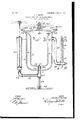
The invention is fully disclosed in the following specilication, of which the accompanying drawing forms a part, in which the separate parts oi' my improvement are designated by suitable reference characters, said drawing being a sectional side elevation oi' adevice embodying' my invention. A
In the practice ot' my invention I provide a main outer receptacle c, which is open at the top and provided with a cover a2, held in place by a transverse arm a, pivoted or hinged at one side, as shown at a", and adapted to be connected with a link, catch, or similar device rf at the opposite side. The arm as is provided centrally with a screw L, which passes therethrough and is provided at its lower end with a ball b2, supported centrally of and on the cover a2 by means of a collar or neck fformed on said cover and having a hollow screwthreaded plug J, through which the screw I) passes, and by means of this construction the cover (t3 may be firmly secured in place, so as to make a perfectly gas-tight connection, and in order to facilitate this operation the top of the receptacle t is flared outwardly, as shown at c, and the cover a2 is provided with a correspondingly-formed iiange or rim a7.
In the bottom of the receptacle a and centrall y thereof is secured a tube c, which is connected with an ordinary coupling c2, in which is secured a standard c, having' a base c", and the tube c communicates with a tube c within the bottom portion of the receptacle aand eX- tending upwardly into said receptacle and placed in the main outer receptacle c is a supplementary receptacle Z or' similar form, having a bottom neck d2, in which the tube ci loosely fits, and the tube .c5 is provided with side ports or passages c6, and the bottom of the receptacle c is also preferably provided with a small port or passage c7, which communicates with the tube c5 and through the tube c5 with the tube o and coupling c2. The upper part of the inner supplemental receptacle Z is also iared outwardly, as shown at (ZS, and closely lits the top portion of the receptacle a just below the cover a2, and the top portion of the receptacle CZ is provided with ports or passages d, and around the receptacle CZ is a space or chamber e, which also extends below said receptacle CZ and separates the receptacles a and d, and the ports or passages Z9 place the chamber e and the chamber or space within the receptacle l in communication.
Connected with the coupling c2 is an ordinary air-pump e2, this connection being made by means of a tube c3 and an ordinary elbowcoupling e", and by means of the air-pump e2 air may be forced into the chamber e and also into the interior of the receptacle d.
At one side of the main outer receptacle a is placed a gage which comprises a glass tube f, in which is placed a piston f2, having a rod f3, which passes up through the tube f and out through a cap f4, secured to the upper end of said tube, and the rod f3 above the cap 7L is provided with a collar f5, and placed on the rod f3 above thecollar f5 are a plurality of weights f, any desired number of which may be employed, and the rod f3 is provided with a scale which is read above the cap f* as the rod f3 is forced upwardly through said cap in the operation of the device. The pressure-gage is connected with a coupling g, which is connected with the top portion oi' the main outer receptacle a, as shown at g2, by means or' a tube g3, an elbow-coupling g4, and a short connecting-,pipe g5, which connects the couplings g and g, and connected with the coupling g opposite the pipe g5 is an ordinary attaching-nozzle g, by means of which this device may be connected with the water-pipes IOO lro
of a building at any point in the usual manner in order to make a test of said pipes, a ilexible hose or any other connecting device being employed for this purpose.
In the use of this device the usual chemicals or other substances intended to produce a smoke are placed in the inner receptacle c. The cover fof the main outer receptacle t is then secured in place, and air is pumped. into the chamber (Z by means of the air-pump c. In this operation the air and smoke intermingle through the ports or passages c, and the air and smoke is forced through the waterpipes throughout the building, and any leakage in said pipes may be quickly determined by the escape of the smoke therethrough. In this operation the amount of pressure in the test-pipes and in the water-pipes is measured by the gage f, the piston being raised by the pressure of air in the lower end of the tube in which said piston is placed, and it will be understood that the amount of pres sure necessary to operate the piston f2 may be regulated as desired by adding to the number otl weights f or decreasing the number of said weights.
This device may also be used as a .fumigator and in making sanitary tests and for other and similar purposes, and changes in and modiiications of the construction herein described may be made without departing `from the spirit ot' my invention or sacriiicing its advantages.
Having fully described my invention, what I claim as new, and desire to secure by Letters Patent, is-
l. A device of the class described, comprising a main outer casing closed at the bottom and open at the top and provided with a removable cover, a supplemental inner casing placed concentrically in the main outer casing and between which and the main outer casing is a chamber in communication with the interior of the supplemental inner casing, an airpump in communication with the main outer casing and a pipe connected with the main outer casing` and provided with an attachingnozzle, substantially as shown and described.
2. A device of the class described, comprising a main outer casing closed at the bottom and open at the top and provided with a removable cover, a supplemental inner casing` placed concentrically in the main outer casing and between which and the main outer casing is a chamber in communication with the interior ot' the supplemental inner casing, an airpump in communication with the main outer casing and a pipe connected with the main outer casing and provided with an attachingnozzle and a pressure-gage, substantially as shown and described.
3. In a device of the class described, a main outer casing open at the top and provided with a removable cover, a supplemental easing supported therein, and between which and the main outer casing is a chamber which is in communication with the supplemental casing, an air-pipe in communication with the interior of both of said casings, and a dischargepipe connected with the main outer casing near the top thereof and provided with a pressure-gage andan attaching-nozzle, substantially as shown and described.
4C. A device of the class described, comprising a main outer casing, asupplemental inner casing centrally therein and in communication with a space between said casings, an air-pump communicating with said space and with the supplemental inner casing, and an escape-pipe connected with the main outer casing` and provided with an attaching-nozzle, substantially as shown and described.
5. A device of the class described, comprising a main outer easing closed at the bottom and open at the top and provided with a removable cover, a supplemental casing placed concentrically in the main outer casing and in communication therewith, an air-pump in communication with the main outer casing, and a pipe connected with the main outer casing and provided with a pressure-gage and an attaching-nozzle, said supplemental inner casing being also provided with a Haring top which fits within the top portion ot' the main outer casing, substantially as shown and described.
In testimony that I claim the foregoing as my invention I have signed my name, in presence of the subscribing witnesses, this 17th day of November, 1904.
CHARLES l). BRADY.
Vitnesses:
F. A. STEWART, C. J. KLEIN.
Priority Applications (1)
| Application Number | Priority Date | Filing Date | Title |
|---|---|---|---|
| US23352104A US792000A (en) | 1904-11-19 | 1904-11-19 | Device for testing water-pipes. |
Applications Claiming Priority (1)
| Application Number | Priority Date | Filing Date | Title |
|---|---|---|---|
| US23352104A US792000A (en) | 1904-11-19 | 1904-11-19 | Device for testing water-pipes. |
Publications (1)
| Publication Number | Publication Date |
|---|---|
| US792000A true US792000A (en) | 1905-06-13 |
Family
ID=2860489
Family Applications (1)
| Application Number | Title | Priority Date | Filing Date |
|---|---|---|---|
| US23352104A Expired - Lifetime US792000A (en) | 1904-11-19 | 1904-11-19 | Device for testing water-pipes. |
Country Status (1)
| Country | Link |
|---|---|
| US (1) | US792000A (en) |
Cited By (1)
| Publication number | Priority date | Publication date | Assignee | Title |
|---|---|---|---|---|
| US3395514A (en) * | 1965-10-27 | 1968-08-06 | Mine Safety Appliances Co | Filter testing system and method |
-
1904
- 1904-11-19 US US23352104A patent/US792000A/en not_active Expired - Lifetime
Cited By (1)
| Publication number | Priority date | Publication date | Assignee | Title |
|---|---|---|---|---|
| US3395514A (en) * | 1965-10-27 | 1968-08-06 | Mine Safety Appliances Co | Filter testing system and method |
Similar Documents
| Publication | Publication Date | Title |
|---|---|---|
| US792000A (en) | Device for testing water-pipes. | |
| US69894A (en) | beaedsleb | |
| US1706567A (en) | Testing apparatus | |
| US836874A (en) | Testing device for plumbers, &c. | |
| US942360A (en) | Regulating-valve. | |
| US243741A (en) | Frederic tudor | |
| US982520A (en) | High and low pressure testing device. | |
| US1234505A (en) | Gas-volume standard for testing volume-measuring apparatus for gas. | |
| US2279611A (en) | Method of making hygrometers | |
| SE8202562L (en) | METHOD FOR DETERMINING GAS FLOW THROUGH A CHANNEL | |
| US387663A (en) | Mercury pressure-gage | |
| US1877487A (en) | Regulator valve | |
| US590241A (en) | schnaiee | |
| US1865623A (en) | Water evacuating device | |
| US1851598A (en) | Attachment for gas governors | |
| US319571A (en) | Relief valve for steam engine cylinders | |
| US271735A (en) | Gas-pressure regulator | |
| US484619A (en) | Henry e | |
| US677470A (en) | Steam-valve. | |
| US515611A (en) | Henry rauser | |
| US524588A (en) | Witnebsrs | |
| US782116A (en) | Heating apparatus. | |
| US1187646A (en) | Tester for pipe systems. | |
| US247767A (en) | Nobbebt keotsgh | |
| JPH0221735B2 (en) |