US791910A - Car-step. - Google Patents
Car-step. Download PDFInfo
- Publication number
- US791910A US791910A US21995804A US1904219958A US791910A US 791910 A US791910 A US 791910A US 21995804 A US21995804 A US 21995804A US 1904219958 A US1904219958 A US 1904219958A US 791910 A US791910 A US 791910A
- Authority
- US
- United States
- Prior art keywords
- steps
- supplemental
- stationary
- bars
- car
- Prior art date
- Legal status (The legal status is an assumption and is not a legal conclusion. Google has not performed a legal analysis and makes no representation as to the accuracy of the status listed.)
- Expired - Lifetime
Links
Images

Classifications
-
- B—PERFORMING OPERATIONS; TRANSPORTING
- B61—RAILWAYS
- B61D—BODY DETAILS OR KINDS OF RAILWAY VEHICLES
- B61D23/00—Construction of steps for railway vehicles
- B61D23/02—Folding steps for railway vehicles, e.g. hand or mechanically actuated
Definitions
- This invention relates to improvements in supplemental steps for cars.
- the object of the invention is to provide, in conjunction with the ordinary stationary steps of the car, one or more additional steps which are normally folded up out of the way against said stationary steps or which may be quickly and easily lowered for use when desired.
- a further object is to provide supplemental steps for railway passenger-cars which will be simple in construction, easily operated to raise or lower the same, and which in their raised or folded position will be entirely out of the way of and will not interfere with the use of the stationary steps-of said cars, means being provided whereby said supplemental steps will be locked together when in their lowered position.
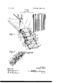
- Figure 1 is a perspective view of a part of one end of a railway passenger-car, showing the application of the supplemental steps, the same being shown in full lines in their lowered position and in dotted lines. in their folded position.
- Fig. 2 is a central vertical sectional View of the stationary steps, showing the supplemental steps in folded position.
- Fig. 3 is a similar view showing the steps in their lower or unfolded position; and
- Fig. 4 is a vertical transverse sectional view through the upper supplemental step and its supporting-links for the same, showing the means whereby said steps are locked together when in lowered position.
- 1 denotes the platform of the car, which is provided with the usual permanent or stationary steps 2.
- the inner ends of rails or bars 3 which are adapted to be swung inwardly and outwardly on said sides and which may be held in their outward position by means of pins at.
- Said pins 4 are adapted to be removably inserted through alined apertures in said bar and the sides of said stationary steps.
- To the lower ends of the side of said stationary steps are pivotally connected, as by bolts 5, the upper ends of angularly-bent arms 6, upon the outer portions of which are secured the ends of the tread portion of the upper supplemental step 7.
- the lower side of the outer portion of the arms 6 are secured downwardly-projecting bracket-arms 8, to the lower ends of which are pivotally connected the lower ends of rods or bars 9, the upper ends of which are pivotally connected to the outer ends of the bars or rails 3, thereby supporting the upper supplemental step.
- the rods or bars 9 are preferably formed in three sections or links suitably hinged or pivoted, as shown.
- pivot-bolts 5 To the pivot-bolts 5 are pivotally connected the upper ends of rods or bars 10, to the outer ends of which are connected the upper ends of zigzag or step-shaped bars 12, to the lower portions of which are secured the lower supplemental step 13.
- the upper portions of the bars 12 are adapted to rest on the brackets 8 when said lower supplemental step is in its lowered and unfolded position, thereby supporting said step through the medium of the bars or rods 9.
- lat erally-projecting cylindrical pins or studs 14 On the outer ends of the lower portion of the bars 12 are secured lat erally-projecting cylindrical pins or studs 14, which when said lower step is folded upwardly are adapted to engage angle iron guide-plates 15.
- Said plates are secured to the inner side pieces of the stationary steps, said lower supplemental step being thereby guided and directed in its upward movement to a position where the same will rest upon the upper stationary step 2.
- the upper ends of the zigzag bars 12 are provided with stoplugs 16, with which are adapted to be engaged the lower ends of the bars 10, thereby limitare in folded or raised position, and to be swung outwardly and downwardly from said ing the downward or unfolded position of the l stationary steps when in an unfolded position,
- a locking mechanism is provided, whereby said steps may be connected together when in open position. When thus locked or connected together, neither of the supplemental steps can be raised without raising the other also.
- Said locking mechanism consists of spring-catches 17,which are mounted on the under side of each inner corner of the upper supplemental step and are adapted to project through the supportingbars 6 for said step and to engage apertures in the supporting-bars 12 of the lower supplemental step, thereby locking said bars 6 and 12 together.
- To the inner ends of the spring-catches 17 are secured the outer ends of rods or wires 18, to the inner ends of which are secured operating-handles 19.
- Said handles when grasped and forced together will withdraw or retract the spring-catches 17 out of engagement with the arms 12, thereby releasing the lower step 13 and permitting the same to be swung up to a folded or raised position.
- the construction of the catches 17 is such that they will automatically engage the arms 12 of the lower step when the same is swung downwardly.
- In each of the supplemental steps midway between the ends of the same and near the inner edges thereof, are formed hand-holes 20, by which the steps may be grasped when it is desired to pull the same downwardly to an unfolded position.
Description
PATENTED JUNE 6, 1905.
E. HOWE. I
CAR STEP.
'APPLIOATION FILED AUG. 8. 1904,
'2 SHEETS- HIET 1.
dazhw wi/lmwm No. 791,910. PATENTED JUNE 6, 1905.
B. HOWE.
GAR STEP.
APPLICATION FILED AUG. 8. 1904.
2 SHEETS-SHEBT 2.
IIIIIIIIIIIIIIII liliii liiii mwwto'c Eafqafjfaw'e v I I I a arrwm,
UNITED STATES Patented June 1.905.
EDGAR HOIVE, OF EVERETT, WVASHINGTON.
CAR-STEP.
SPECIFICATION forming part of Letters Patent No. 791,910, dated June 6, 1905.
Application filed August 8, 1904. Serial No. 219,958.
To all whom, it may concern.-
Be it known that I, EDGAR HOWE, a citizen of the United States, residing at Everett, in the county of Snohomish and State of Washington, have invented certain new and useful Improvements in Car-Steps; and I do cleclare the following to be a full, clear, and exact description of the invention, such as will enable others skilled in the art to which it ap pertains to make and use the same.
This invention relates to improvements in supplemental steps for cars.
The object of the invention is to provide, in conjunction with the ordinary stationary steps of the car, one or more additional steps which are normally folded up out of the way against said stationary steps or which may be quickly and easily lowered for use when desired.
A further object is to provide supplemental steps for railway passenger-cars which will be simple in construction, easily operated to raise or lower the same, and which in their raised or folded position will be entirely out of the way of and will not interfere with the use of the stationary steps-of said cars, means being provided whereby said supplemental steps will be locked together when in their lowered position. With these and other objects in view the invention consists of certain novel features of construction, combination, and arrangement of parts, as will be hereinafter more fully described, and pointed out in the appended claims.
In the accompanying drawings, Figure 1 is a perspective view of a part of one end of a railway passenger-car, showing the application of the supplemental steps, the same being shown in full lines in their lowered position and in dotted lines. in their folded position. Fig. 2 is a central vertical sectional View of the stationary steps, showing the supplemental steps in folded position. Fig. 3 is a similar view showing the steps in their lower or unfolded position; and Fig. 4 is a vertical transverse sectional view through the upper supplemental step and its supporting-links for the same, showing the means whereby said steps are locked together when in lowered position.
Referring more particularly to the drawings, 1 denotes the platform of the car, which is provided with the usual permanent or stationary steps 2. To the side pieces of the permanent steps 2, near the upper end of the same, are pivotally connected the inner ends of rails or bars 3, which are adapted to be swung inwardly and outwardly on said sides and which may be held in their outward position by means of pins at. Said pins 4 are adapted to be removably inserted through alined apertures in said bar and the sides of said stationary steps. To the lower ends of the side of said stationary steps are pivotally connected, as by bolts 5, the upper ends of angularly-bent arms 6, upon the outer portions of which are secured the ends of the tread portion of the upper supplemental step 7. To
the lower side of the outer portion of the arms 6 are secured downwardly-projecting bracket-arms 8, to the lower ends of which are pivotally connected the lower ends of rods or bars 9, the upper ends of which are pivotally connected to the outer ends of the bars or rails 3, thereby supporting the upper supplemental step. The rods or bars 9 are preferably formed in three sections or links suitably hinged or pivoted, as shown.
To the pivot-bolts 5 are pivotally connected the upper ends of rods or bars 10, to the outer ends of which are connected the upper ends of zigzag or step-shaped bars 12, to the lower portions of which are secured the lower supplemental step 13. The upper portions of the bars 12 are adapted to rest on the brackets 8 when said lower supplemental step is in its lowered and unfolded position, thereby supporting said step through the medium of the bars or rods 9. On the outer ends of the lower portion of the bars 12 are secured lat erally-projecting cylindrical pins or studs 14, which when said lower step is folded upwardly are adapted to engage angle iron guide-plates 15. Said plates are secured to the inner side pieces of the stationary steps, said lower supplemental step being thereby guided and directed in its upward movement to a position where the same will rest upon the upper stationary step 2. The upper ends of the zigzag bars 12 are provided with stoplugs 16, with which are adapted to be engaged the lower ends of the bars 10, thereby limitare in folded or raised position, and to be swung outwardly and downwardly from said ing the downward or unfolded position of the l stationary steps when in an unfolded position,
lower supplemental step.
In order to prevent the casual movement of the steps 7 and 13, a locking mechanism is provided, whereby said steps may be connected together when in open position. When thus locked or connected together, neither of the supplemental steps can be raised without raising the other also. Said locking mechanism consists of spring-catches 17,which are mounted on the under side of each inner corner of the upper supplemental step and are adapted to project through the supportingbars 6 for said step and to engage apertures in the supporting-bars 12 of the lower supplemental step, thereby locking said bars 6 and 12 together. To the inner ends of the spring-catches 17 are secured the outer ends of rods or wires 18, to the inner ends of which are secured operating-handles 19. Said handles when grasped and forced together will withdraw or retract the spring-catches 17 out of engagement with the arms 12, thereby releasing the lower step 13 and permitting the same to be swung up to a folded or raised position. The construction of the catches 17 is such that they will automatically engage the arms 12 of the lower step when the same is swung downwardly. In each of the supplemental steps, midway between the ends of the same and near the inner edges thereof, are formed hand-holes 20, by which the steps may be grasped when it is desired to pull the same downwardly to an unfolded position.
From the foregoing description, taken in connection with the accompanying drawings, the construction and operation of the invention will be readily understood without requiring a more extended explanation.
Various changes in the form, proportion, and the minor details of construction may be resorted to without departing from the principle or sacrificing any of the advantages of this invention.
Having thus described my invention, what I claim as new, and desire to secure by Letters Patent, is*
1. The combination with the stationary steps of a car-platform, of a pair of supplemental steps, each independently pivotally connected to said stationary steps, said. supplemental steps being adapted to engage and rest on said stationary steps when the former pivoted supporting-rails, sectional foldable supporting-bars arranged to support said supplemental steps when in a lowered position, and means to lock said supplemental steps together when in a lowered position, so that neither can be raised without also raising the other.
2. The combination with the stationary steps of a car-platform, of a pair of supplemental steps, each independently pivotally connected to said stationary steps, said supplemental steps being adapted to engage and rest on said stationary steps when the former are in folded or raised position and to be swung outwardly and downwardly from said stationary steps when in an unfolded position, pivoted supporting-rails and sectional foldable supporting-bars arranged to support said supplemental steps when in a lowered position, and means for locking said supplemental steps together when in a lowered position, said locking means having releasing devices whereby said supplemental steps may be disconnected from each other.
3. The combination with the stationary steps of a car-platform, of a pair of supplemental steps independently pivotally connected to said stationary steps, said supplemental steps being adapted to engage and rest on said stationary steps when the former are in folded or raised position, and to be swung outwardly and downwardly from said stationary steps when in an unfolded position, pivoted supporting-rails and sectional foldable supporting-bars arranged to support said supplemen tal steps when in a lowered position, springcatches arranged on said upper supplemental steps and adapted to automatically engage the supporting-bars of said lower supplemental steps, whereby said supplemental steps are locked together when in their lowered position, and means whereby said catches may be I00 simultaneously released to permit said supplemental steps to be disengaged from each other and swung up, substantially as described.
In testimony whereof I have hereunto set my hand in presence of two subscribing wit- 5 nesses.
EDGAR HOWE. IVitnesses:
G. P. SPRIESTERSBACH, C. J. WITT.
Priority Applications (1)
| Application Number | Priority Date | Filing Date | Title |
|---|---|---|---|
| US21995804A US791910A (en) | 1904-08-08 | 1904-08-08 | Car-step. |
Applications Claiming Priority (1)
| Application Number | Priority Date | Filing Date | Title |
|---|---|---|---|
| US21995804A US791910A (en) | 1904-08-08 | 1904-08-08 | Car-step. |
Publications (1)
| Publication Number | Publication Date |
|---|---|
| US791910A true US791910A (en) | 1905-06-06 |
Family
ID=2860399
Family Applications (1)
| Application Number | Title | Priority Date | Filing Date |
|---|---|---|---|
| US21995804A Expired - Lifetime US791910A (en) | 1904-08-08 | 1904-08-08 | Car-step. |
Country Status (1)
| Country | Link |
|---|---|
| US (1) | US791910A (en) |
-
1904
- 1904-08-08 US US21995804A patent/US791910A/en not_active Expired - Lifetime
Similar Documents
| Publication | Publication Date | Title |
|---|---|---|
| US791910A (en) | Car-step. | |
| US559965A (en) | bierstadt | |
| US559966A (en) | bieestadt | |
| US538161A (en) | Collapsible gate for railway-cars | |
| US559964A (en) | bieestadt | |
| US1129238A (en) | Extensible car-step. | |
| US672564A (en) | Railway-car. | |
| US907183A (en) | Folding car-stake. | |
| US338048A (en) | Liott | |
| US243932A (en) | maetel | |
| US623039A (en) | Gate for cars | |
| US760916A (en) | Running-board for railway-cars. | |
| US661453A (en) | Railway-car step. | |
| US559963A (en) | bierstadt | |
| US604602A (en) | Funeral-car | |
| US567524A (en) | Folding stretcher | |
| US649804A (en) | Convertible car. | |
| US711164A (en) | Railway-car. | |
| US481009A (en) | Car-step extension | |
| US322749A (en) | Car-step | |
| US759285A (en) | Freight-car. | |
| US302550A (en) | ferguson | |
| US689629A (en) | Folding car-step. | |
| US676775A (en) | Automatic and adjustable car-step. | |
| US822474A (en) | Car construction. |