US7916586B2 - Near field optical recording/reproducing apparatus and method of normalizing gap error signal of the same - Google Patents
Near field optical recording/reproducing apparatus and method of normalizing gap error signal of the same Download PDFInfo
- Publication number
- US7916586B2 US7916586B2 US12/128,006 US12800608A US7916586B2 US 7916586 B2 US7916586 B2 US 7916586B2 US 12800608 A US12800608 A US 12800608A US 7916586 B2 US7916586 B2 US 7916586B2
- Authority
- US
- United States
- Prior art keywords
- error signal
- amplitude
- near field
- reproducing apparatus
- optical recording
- Prior art date
- Legal status (The legal status is an assumption and is not a legal conclusion. Google has not performed a legal analysis and makes no representation as to the accuracy of the status listed.)
- Expired - Fee Related, expires
Links
Images


Classifications
-
- G—PHYSICS
- G11—INFORMATION STORAGE
- G11B—INFORMATION STORAGE BASED ON RELATIVE MOVEMENT BETWEEN RECORD CARRIER AND TRANSDUCER
- G11B7/00—Recording or reproducing by optical means, e.g. recording using a thermal beam of optical radiation by modifying optical properties or the physical structure, reproducing using an optical beam at lower power by sensing optical properties; Record carriers therefor
- G11B7/08—Disposition or mounting of heads or light sources relatively to record carriers
- G11B7/09—Disposition or mounting of heads or light sources relatively to record carriers with provision for moving the light beam or focus plane for the purpose of maintaining alignment of the light beam relative to the record carrier during transducing operation, e.g. to compensate for surface irregularities of the latter or for track following
-
- G—PHYSICS
- G11—INFORMATION STORAGE
- G11B—INFORMATION STORAGE BASED ON RELATIVE MOVEMENT BETWEEN RECORD CARRIER AND TRANSDUCER
- G11B7/00—Recording or reproducing by optical means, e.g. recording using a thermal beam of optical radiation by modifying optical properties or the physical structure, reproducing using an optical beam at lower power by sensing optical properties; Record carriers therefor
- G11B7/12—Heads, e.g. forming of the optical beam spot or modulation of the optical beam
- G11B7/135—Means for guiding the beam from the source to the record carrier or from the record carrier to the detector
- G11B7/1387—Means for guiding the beam from the source to the record carrier or from the record carrier to the detector using the near-field effect
-
- G—PHYSICS
- G11—INFORMATION STORAGE
- G11B—INFORMATION STORAGE BASED ON RELATIVE MOVEMENT BETWEEN RECORD CARRIER AND TRANSDUCER
- G11B7/00—Recording or reproducing by optical means, e.g. recording using a thermal beam of optical radiation by modifying optical properties or the physical structure, reproducing using an optical beam at lower power by sensing optical properties; Record carriers therefor
- G11B7/08—Disposition or mounting of heads or light sources relatively to record carriers
- G11B7/09—Disposition or mounting of heads or light sources relatively to record carriers with provision for moving the light beam or focus plane for the purpose of maintaining alignment of the light beam relative to the record carrier during transducing operation, e.g. to compensate for surface irregularities of the latter or for track following
- G11B7/0908—Disposition or mounting of heads or light sources relatively to record carriers with provision for moving the light beam or focus plane for the purpose of maintaining alignment of the light beam relative to the record carrier during transducing operation, e.g. to compensate for surface irregularities of the latter or for track following for focusing only
-
- G—PHYSICS
- G11—INFORMATION STORAGE
- G11B—INFORMATION STORAGE BASED ON RELATIVE MOVEMENT BETWEEN RECORD CARRIER AND TRANSDUCER
- G11B7/00—Recording or reproducing by optical means, e.g. recording using a thermal beam of optical radiation by modifying optical properties or the physical structure, reproducing using an optical beam at lower power by sensing optical properties; Record carriers therefor
- G11B7/08—Disposition or mounting of heads or light sources relatively to record carriers
- G11B7/09—Disposition or mounting of heads or light sources relatively to record carriers with provision for moving the light beam or focus plane for the purpose of maintaining alignment of the light beam relative to the record carrier during transducing operation, e.g. to compensate for surface irregularities of the latter or for track following
- G11B7/0941—Methods and circuits for servo gain or phase compensation during operation
Definitions
- aspects of the present invention relate to a near field optical recording/reproducing apparatus, and a method of normalizing a gap error signal of the same, and more particularly, to a near field optical recording/reproducing apparatus which can maintain a gap error signal constant during recording and reproducing operations by normalizing the gap error signal, and a method of normalizing the gap error signal of the same.
- BDs Blu-ray discs
- HD-DVDs High Definition DVDs
- CDs compact discs
- DVDs digital versatile discs
- Such commercialized technologies for CDs, DVDs, BDs, and HD-DVDs involve far field storage technology in which a distance from an optical head of an optical recording/reproducing apparatus to a recording surface of an optical disc is about 1-2 mm.
- SIL solid immersion lens
- a considerable portion of the optical spot is totally reflected by the SIL and proceeds back to the objective lens.
- light of a very slight intensity exists on an opposite surface of the SIL and such a light is referred to as an evanescent wave.
- information can be recorded or reproduced with respect to the optical disc by transferring the energy of the evanescent wave to the optical disc through a narrow air gap between the SIL and the optical disc.
- the distance between the SIL and the optical disc can be obtained by measuring the intensity of light that is being totally reflected by the SIL. That is, the facts that an amount of light totally reflected by the SIL is maximized in a far field state, and an amount of light that is totally reflected by the SIL decreases as the distance between the SIL and the optical disc decreases in a near field state, are used.
- a light signal that proceeds back by being totally reflected by the SIL is generally referred to as a gap error signal (GES).
- GES gap error signal
- the distance between the SIL and the optical disc can be estimated to be about 50 nm, for example.
- an amplitude of the GES is affected by the intensity of the light provided by a light source, when an intensity of a driving signal for driving the light source changes, it is difficult to accurately measure or detect the distance between the SIL and the optical disc.
- the intensity of the light during a recording operation is about ten times greater than that during a reproduction operation, the amplitude of the GES remarkably changes when a recording mode is switched to a reproducing mode or vice versa.
- normalization of the GES is needed to make the GES constant regardless of the intensity of the driving signal of the light source.
- aspects of the present invention provide a near field optical recording/reproducing apparatus which can maintain a constant gap error signal (GES) during recording and reproduction operations by normalizing the GES, and a method of normalizing the GES of the same.
- GES constant gap error signal
- a near field optical recording/reproducing apparatus includes a light source to emit light, an objective lens to form a spot by focusing the light emitted from the light source, a solid immersion lens to generate an evanescent wave of the light from the spot of the light formed by the objective lens, a photodetector to measure an amplitude of a gap error signal from the light that is totally reflected by the solid immersion lens, and an operating unit to generate a normalized gap error signal by using an amplitude of a driving signal applied to the light source to emit the light and the amplitude of the gap error signal measured by the photodetector.
- the operating unit calculates a normalization factor by dividing the amplitude of the driving signal, measured in a far field state of the near field optical recording/reproducing apparatus, by the amplitude of the gap error signal, measured in the far field state thereof.
- the operating unit generates a normalized gap error signal by dividing the amplitude of the gap error signal, measured during reproduction or recording operations of the near field optical recording/reproducing apparatus, by the amplitude of the driving signal, measured during the reproduction or recording operations of the near field optical recording/reproducing apparatus, and multiplying a result of the division by the normalization factor.
- the near field optical recording/reproducing apparatus further includes a first low pass filter arranged between the light source and the operating unit with respect to the driving signal, and removing a high frequency component of the driving signal provided to the operating unit, and a second low pass filter arranged between the photodetector and the operating unit with respect to the gap error signal, and removing a high frequency component of the gap error signal provided to the operating unit.
- the near field optical recording/reproducing apparatus further includes an actuator having the objective lens and the solid immersion lens mounted thereon and performing a gap servo operation according to the normalized gap error signal provided by the operating unit.
- a method of normalizing a gap error signal of a near field optical recording/reproducing apparatus includes measuring an amplitude of a driving signal applied to a light source of the near field optical recording/reproducing apparatus and an amplitude of the gap error signal in a far field state of the near field optical recording/reproducing apparatus when the near field optical recording/reproducing apparatus is initialized, calculating a normalization factor by dividing the amplitude of the driving signal applied to the light source by the amplitude of the gap error signal measured in the far field state, measuring the amplitude of the driving signal applied to the light source and the amplitude of the gap error signal during reproduction or recording operations of the near field optical recording/reproducing apparatus, and generating a normalized gap error signal by dividing the amplitude of the gap error signal measured during the reproduction or recording operations of the near field optical recording/reproducing apparatus, by the amplitude of the driving signal measured during the reproduction or recording operations of the near field optical recording/reproducing apparatus, and multiplying a result of the division by
- the method further includes performing a gap servo operation of the near field optical recording/reproducing apparatus according to the normalized gap error signal.
- the method further includes removing high frequency components of the driving signal and the gap error signal using a low pass filter prior to the calculating of the normalization factor and the generating of the normalized gap error signal.
- the normalized gap error signal is constantly maintained to be a preset optimized value regardless of the recording and reproduction operations of the near field optical recording/reproducing apparatus.
- a method of performing a gap servo control of a near field optical recording/reproducing apparatus using a normalized gap error signal includes: measuring an amplitude of a gap error signal from a portion of a focused light that is totally reflected from a solid immersion lens of the near field optical recording/reproducing apparatus; generating the normalized gap error signal that maintains a constant value during both a recording operation and a reproducing operation of the near field optical recording/reproducing apparatus; and using the normalized gap error signal to maintain a constant gap between the solid immersion lens and an optical medium.
- FIG. 1 illustrates a structure of a near field optical recording/reproducing apparatus according to an aspect of the present invention
- FIG. 2 is a flow chart for explaining an operational sequence of the near field optical recording/reproducing apparatus of FIG. 1 ;
- FIG. 3 illustrates a structure and operation of a near field optical recording/reproducing apparatus according to another aspect of the present invention.
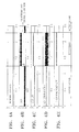
- FIGS. 4A-4E illustrate changes in driving signals and a GESs between reproduction operations and recording operations in a near field optical recording/reproducing apparatus according to an aspect of the present invention.
- FIG. 1 illustrates a structure of a near field optical recording/reproducing apparatus 10 according to an aspect of the present invention.
- the near field optical recording/reproducing apparatus 10 includes a light source 11 , a collimating lens 12 , first and second beam splitters 13 and 14 , a 1 ⁇ 4 wave plate 15 , an objective lens 16 , a solid immersion lens (SIL) 17 , first and second photodetectors 20 and 21 , an operating unit 22 , and an actuator 23 .
- SIL solid immersion lens
- the light source 11 provides a light beam (or a light) to record information to an optical disc D or reproduce information from the optical disc D.
- a blue laser diode (LD) of a 405 nm wavelength can be used as the light source 11 .
- the collimating lens 12 converts the light beam emitted by the light source 11 to a parallel beam.
- the first beam splitter 13 transmits the light from the light source 11 and reflects light that is totally reflected from the SIL 17 towards the first photodetector 20 .
- the second beam splitter 14 transmits the light from the light source 11 and reflects the light reflected from the optical disc D towards the second photodetector 21 .
- the first and second beam splitters 13 and 14 can be polarized beam splitters that transmit or reflect an incident light according to the polarizing direction of the incident light.
- the 1 ⁇ 4 wave plate 15 delays the phase of the incident light by a 1 ⁇ 4 wave. Thus, when the light passes the 1 ⁇ 4 wave plate 15 twice, the polarization direction of the light is changed, for example, from an S-polarization to a P-polarization or vice versa.
- the objective lens 16 focuses the light provided by the light source 11 and forms a spot on a surface of the SIL 17 . As described above, a part of the light that forms the spot is totally reflected from the surface of the SIL 17 and proceeds back to the light source 11 . In doing so, a fine evanescent wave is formed on an opposite surface of the SIL 17 that faces the optical disc D. When the distance between the optical disc D and the SIL 17 is less than 100 nm, that is, in the near field state, the evanescent wave is transferred to (or incident on) the optical disc D so as to be used for recording/reproduction of information.
- the first photodetector 20 detects an amplitude of a gap error signal (GES) that is totally reflected from the surface of the SIL 17 and then reflected by the first beam splitter 13 .
- a gap error signal (GES) refers to a light signal that proceeds back by being totally reflected by the SIL 17 .
- the operating unit 22 receives the amplitude of the GES detected by the first photodetector 20 and an amplitude of a driving signal of the light provided to the light source 11 , and calculates a normalized GES (GESn). As described above, the amplitude of the GES detected by the first photodetector 20 is also affected by the intensity of the light provided by the light source 11 . Thus, the operating unit 22 calculates the GESn that is not affected by the amplitude of the driving signal provided to the light source 11 , by referring to the amplitude of the driving signal provided to the light source 11 . The GESn obtained as above is transmitted to the actuator 23 so as to be used for performing a gap servo operation of the SIL 17 relative to the optical disc D.
- GESn normalized GES
- the second detector 21 detects the intensity of the light input through the second beam splitter 14 after the light is reflected from the optical disc D.
- the second photodetector 21 is a multi-divided photodetector that is divided into a plurality of segments.
- the sum of the intensity of light detected by the respective segments is an RFSUM signal that is used for the reproduction of information from the optical disc D.
- a difference in the intensity of the light detected in the respective segments is a tracking error (TE) signal that is used to perform a tracking servo operation according to a well-known technique. Since the RFSUM signal and the TE signal are not directly related to aspects of the present invention and are also well-known techniques, a detailed description thereof will be omitted herein.
- the actuator 23 has the objective lens 16 and the SIL 17 mounted thereon, and performs a gap servo operation and a tracking servo operation based the GESn and the tracking error signal.
- FIG. 2 is a flow chart for explaining an operational sequence of the near field optical recording/reproducing apparatus 10 , according to an aspect of the present invention. Referring to FIGS. 1 and 2 , an operation of the near field optical recording/reproducing apparatus 10 and a method of normalizing a gap error signal (GES) will now be described in detail.
- GES gap error signal
- an initial tilt of the optical disc D is adjusted in an initialization operation (S 215 ).
- the actuator 23 is moved up and down to determine the amplitude of the GES in the far field state (a far field level) and the amplitude of the GES in a state in which the optical disc D contacts the SIL 17 (a contact level) (S 220 ). These operations are the same as an initialization operation of a typical near field optical recording/reproducing apparatus.
- the SIL 17 is moved to a far field position using the actuator 23 .
- the normalization factor ⁇ calculated by the operating unit 22 is obtained by dividing the amplitude LD_Driving_Level of the driving signal applied to the light source 11 by the amplitude GES_Level of the GES detected by the first photodetector 20 in the far field state (S 225 ).
- the actuator 23 is pulled-in to a near field position so that the gap servo and tracking servo are possible (or enabled) for reproduction (S 230 ). Then, the amplitude LD_Driving_Level of the driving signal applied to the light source 11 and the amplitude GES_Level of the GES are continuously measured.
- the GESn calculated by the operating unit 22 is obtained by dividing the amplitude GES_Level of the GES measured during a reproduction operation by the amplitude LD_Driving_Level of the driving signal measured during the reproduction operation, and then, multiplying a result of the division by the normalization factor ⁇ (S 240 ).
- the GESn 1 (that is, equal to 1).
- the value of GES_Level decreases, GESn ⁇ 1 (that is, less than 1).
- the gap servo of the actuator 23 is controlled using the GESn value output from the operating unit 22 (S 245 ), and the reproduction operation begins while maintaining a preset optimal GESn value (S 250 ). For example, when the optimal distance between the SIL 17 and the optical disc D is 50 nm, the gap servo is controlled such that the GESn value is maintained constant to be 0.5 by using the operating unit 22 and the actuator 23 . If the near field optical recording/reproducing apparatus 10 is not switched to a recording mode (No of S 255 ), the reproduction is continued (S 265 ).
- the gap servo can be controlled for a recording operation (operations S 265 -S 280 ) in the same manner as performed for the reproduction operation (operations S 230 -S 245 ). That is, in a state in which the actuator 23 is pulled-in to the near field position so that the gap servo and the tracking servo are possible (operation S 260 ), the amplitude LD_Driving_Level of the driving signal and the amplitude GES_Level of the GES are continuously measured (S 270 ).
- the operating unit 22 obtains the GESn according to Equation 2 using the amplitude LD_Driving_Level of the driving signal and the amplitude GES_Level of the GES (operation S 275 ).
- the gap servo of the actuator 23 is controlled using the GESn value output from the operating unit 22 (S 280 ), and the recording operation begins while maintaining a preset optimal GESn value (S 285 ).
- the amplitude LD_Driving_Level of the driving signal applied to the light source 11 is increased by about ten times greater than that in the reproducing mode.
- the amplitude GES_Level of the GES measured by the first photodetector 20 is also proportionally increased.
- GESn 1 in the far field state and GESn ⁇ 1 in the near field state.
- GESn 0.
- the gap servo of the actuator 23 can be controlled using the GESn value output from the operating unit 22 .
- Recording can be performed while maintaining the preset optimal GESn value.
- the gap servo is controlled to maintain the GESn value to be 0.5 using the operating unit 22 and the actuator 23 .
- the GESn can be maintained constant.
- the gap servo can be stably controlled by using the GESn.
- the GES is normalized using the amplitude of the driving signal applied directly to the light source 11 , a separate optical system and a photodetector to measure a change in the intensity of the light output from the light source 11 are not needed for the normalization of the GES.
- an additional process to adjust a gain and an offset of the separate photodetector is not needed and it is possible to very accurately normalize the GES.
- FIG. 3 illustrates a structure and operation of a near field optical recording/reproducing apparatus according to another aspect of the present invention.
- the near field optical recording/reproducing apparatus of FIG. 3 is different for the near field optical recording/reproducing apparatus of FIG. 1 in that a buffer 18 a and a low pass filter (LPF) 18 b , and a buffer 19 a and an LPF 19 b , are respectively further provided between the light source 11 and the operating unit 22 , and between the first photodetector 20 and the operating unit 22 .
- LPF low pass filter
- FIGS. 4A-4E illustrate changes in the driving signals and the GESs between reproduction and recording operations in a near field optical recording/reproducing apparatus, according to an aspect of the present invention.
- FIG. 4D the driving signals during reproduction and during recording operations are shown.
- the driving signal is maintained almost constant.
- the driving signal has a pulse wave form and the amount of peaks is increased.
- FIG. 4E shows the driving signal after passing through the LPF 18 b . Referring to FIG. 4E , it can be seen that the driving signal during the recording operation after passing through the LPF 18 b is maintained constant.
- FIG. 4B shows the GES during the reproduction operation and during the recording operation.
- the GES is maintained almost constant, during the recording operation, however, the GES has a pulse wave form.
- the amplitude of the driving signal increases, the amplitude of the GES increases as well.
- FIG. 4C shows the GES after passing through the LPF 19 b . It can be seen that the GES during the recording operation after passing through the LPF 19 b is maintained constant.
- FIG. 4A shows a normalized GES according to aspects of the present invention. As can be seen from FIG. 4A , the normalized GES according to an aspect of the present invention can maintain a constant value both during the reproduction operation and during the recording operation. Thus, by using the normalized GES, accurate gap servo control is possible during the reproduction operation and during the recording operation.
- an optical recording/reproducing apparatus refers to an optical recording and/or reproducing apparatus.
- An optical recording and/or reproducing apparatus refers to an optical recording and reproducing apparatus, an optical recording apparatus, or an optical reproducing apparatus.
Landscapes
- Physics & Mathematics (AREA)
- Optics & Photonics (AREA)
- Optical Head (AREA)
- Optical Recording Or Reproduction (AREA)
Abstract
Description
α=(LD_Driving_Level)/(GES_Level) [Equation 1]
GESn=α×(GES_Level)/(LD_Driving_Level) [Equation 2]
Claims (20)
Applications Claiming Priority (3)
| Application Number | Priority Date | Filing Date | Title |
|---|---|---|---|
| KR1020080002929A KR20090077145A (en) | 2008-01-10 | 2008-01-10 | Near-field optical recording / reproducing apparatus and gap error signal normalization method of the apparatus |
| KR2008-2929 | 2008-01-10 | ||
| KR10-2008-0002929 | 2008-01-10 |
Publications (2)
| Publication Number | Publication Date |
|---|---|
| US20090180372A1 US20090180372A1 (en) | 2009-07-16 |
| US7916586B2 true US7916586B2 (en) | 2011-03-29 |
Family
ID=40850512
Family Applications (1)
| Application Number | Title | Priority Date | Filing Date |
|---|---|---|---|
| US12/128,006 Expired - Fee Related US7916586B2 (en) | 2008-01-10 | 2008-05-28 | Near field optical recording/reproducing apparatus and method of normalizing gap error signal of the same |
Country Status (3)
| Country | Link |
|---|---|
| US (1) | US7916586B2 (en) |
| KR (1) | KR20090077145A (en) |
| WO (1) | WO2009088127A1 (en) |
Families Citing this family (5)
| Publication number | Priority date | Publication date | Assignee | Title |
|---|---|---|---|---|
| JP2009158007A (en) * | 2007-12-26 | 2009-07-16 | Sony Corp | Optical pickup device, optical recording / reproducing device, and gap control method |
| EP2299444A1 (en) * | 2009-09-15 | 2011-03-23 | Thomson Licensing | Near-field optical recording apparatus, method and medium |
| CN102237100A (en) * | 2010-04-23 | 2011-11-09 | 建兴电子科技股份有限公司 | Lens push-in method in near field optical access system |
| US8854939B2 (en) * | 2011-03-22 | 2014-10-07 | Panasonic Corporation | Optical information apparatus and gap control method thereof |
| CN113509570B (en) * | 2021-05-17 | 2022-05-31 | 四川大学 | Feeding bottle degassing unit based on low temperature plasma |
Citations (8)
| Publication number | Priority date | Publication date | Assignee | Title |
|---|---|---|---|---|
| US6292442B1 (en) | 1998-03-12 | 2001-09-18 | Pioneer Electronic Corporation | Optical head |
| US6693705B2 (en) | 2001-12-28 | 2004-02-17 | Electronics And Telecommunications Research Institute | Apparatus for measuring slant angle of solid immersion lens |
| US6717896B1 (en) | 1999-07-07 | 2004-04-06 | Sony Corporation | Controlling a gap length in a near-field area in an exposure apparatus |
| US6845066B1 (en) | 1998-10-28 | 2005-01-18 | Sony Corporation | Focus control method and focus controller |
| US20070217300A1 (en) * | 2006-03-15 | 2007-09-20 | Canon Kabushiki Kaisha | Optical information recording/reproducing apparatus |
| WO2007114567A1 (en) | 2006-04-04 | 2007-10-11 | Lg Electronics Inc. | Data recording/reproducing method and apparatus |
| US20070280065A1 (en) * | 2006-06-05 | 2007-12-06 | Canon Kabushiki Kaisha | Optical information recording/reproduction apparatus |
| US20080037380A1 (en) * | 2006-08-09 | 2008-02-14 | Sony Corporation | Optical disk apparatus and servo control method |
-
2008
- 2008-01-10 KR KR1020080002929A patent/KR20090077145A/en not_active Withdrawn
- 2008-05-23 WO PCT/KR2008/002877 patent/WO2009088127A1/en not_active Ceased
- 2008-05-28 US US12/128,006 patent/US7916586B2/en not_active Expired - Fee Related
Patent Citations (9)
| Publication number | Priority date | Publication date | Assignee | Title |
|---|---|---|---|---|
| US6292442B1 (en) | 1998-03-12 | 2001-09-18 | Pioneer Electronic Corporation | Optical head |
| US6845066B1 (en) | 1998-10-28 | 2005-01-18 | Sony Corporation | Focus control method and focus controller |
| US6717896B1 (en) | 1999-07-07 | 2004-04-06 | Sony Corporation | Controlling a gap length in a near-field area in an exposure apparatus |
| US6693705B2 (en) | 2001-12-28 | 2004-02-17 | Electronics And Telecommunications Research Institute | Apparatus for measuring slant angle of solid immersion lens |
| US20070217300A1 (en) * | 2006-03-15 | 2007-09-20 | Canon Kabushiki Kaisha | Optical information recording/reproducing apparatus |
| WO2007114567A1 (en) | 2006-04-04 | 2007-10-11 | Lg Electronics Inc. | Data recording/reproducing method and apparatus |
| US20070280065A1 (en) * | 2006-06-05 | 2007-12-06 | Canon Kabushiki Kaisha | Optical information recording/reproduction apparatus |
| US20080037380A1 (en) * | 2006-08-09 | 2008-02-14 | Sony Corporation | Optical disk apparatus and servo control method |
| US7755986B2 (en) * | 2006-08-09 | 2010-07-13 | Sony Corporation | Optical disk apparatus and servo control method |
Non-Patent Citations (1)
| Title |
|---|
| International Search Report dated Aug. 19, 2008 of the PCT International Application No. PCT/KR2008/002877. |
Also Published As
| Publication number | Publication date |
|---|---|
| US20090180372A1 (en) | 2009-07-16 |
| KR20090077145A (en) | 2009-07-15 |
| WO2009088127A1 (en) | 2009-07-16 |
Similar Documents
| Publication | Publication Date | Title |
|---|---|---|
| US7916586B2 (en) | Near field optical recording/reproducing apparatus and method of normalizing gap error signal of the same | |
| US7808866B2 (en) | Apparatus and method for recording/reproducing data on/from a recording medium | |
| JP2008243282A (en) | Optical information recording / reproducing device | |
| US20080205249A1 (en) | Compatible optical pickup and optical information storage medium system employing- the same | |
| US20070008858A1 (en) | Optical pickup and optical disc apparatus | |
| US7920449B2 (en) | Method of controlling focus of optical information storage media recording and/or reproduction apparatus and apparatus therefor | |
| JP2008041219A (en) | Optical disc apparatus and servo control method | |
| KR100803592B1 (en) | Compatible optical pickups and optical recording and / or reproducing apparatus employing the same | |
| US20070280065A1 (en) | Optical information recording/reproduction apparatus | |
| US9064506B2 (en) | Writable information recording and reproducing apparatus | |
| JPH10283644A (en) | Focus control apparatus and method, optical disc apparatus | |
| US7623435B2 (en) | Optical pickup device, and information recording and reproduction device | |
| KR101350988B1 (en) | Method and apparatus for generating tracking error signal and optical information storage system employing the same | |
| JP5309008B2 (en) | Optical information recording / reproducing apparatus and optical information reproducing apparatus | |
| JP3811633B2 (en) | Optical head and driving method thereof | |
| KR100739660B1 (en) | Optical pickup apparatus and method for detecting thickness of recording medium | |
| JP4231619B2 (en) | Optical pickup device | |
| KR100600587B1 (en) | Optical pickup | |
| JP2004014047A (en) | Optical disc device and aberration compensation method in optical disc device | |
| CN101288125A (en) | An apparatus and method for recording/reproducing data on/from a recording medium | |
| JP2008112490A (en) | Optical recording medium reproducing device and optical pickup device | |
| JP2011023095A (en) | Optical disk device | |
| KR20080069786A (en) | How to set the initial position of the actuator | |
| KR20080004716A (en) | Optical recording and reproducing apparatus and recording and reproducing method | |
| JP2005174418A (en) | Optical information recording / reproducing apparatus |
Legal Events
| Date | Code | Title | Description |
|---|---|---|---|
| AS | Assignment |
Owner name: SAMSUNG ELECTRONICS CO., LTD., KOREA, REPUBLIC OF Free format text: ASSIGNMENT OF ASSIGNORS INTEREST;ASSIGNORS:JEONG, AN-SIK;SHIN, JONG-HYUN;KIM, IN-JOO;AND OTHERS;REEL/FRAME:021056/0480 Effective date: 20080506 |
|
| FEPP | Fee payment procedure |
Free format text: PAYOR NUMBER ASSIGNED (ORIGINAL EVENT CODE: ASPN); ENTITY STATUS OF PATENT OWNER: LARGE ENTITY |
|
| FEPP | Fee payment procedure |
Free format text: PAYOR NUMBER ASSIGNED (ORIGINAL EVENT CODE: ASPN); ENTITY STATUS OF PATENT OWNER: LARGE ENTITY Free format text: PAYER NUMBER DE-ASSIGNED (ORIGINAL EVENT CODE: RMPN); ENTITY STATUS OF PATENT OWNER: LARGE ENTITY |
|
| REMI | Maintenance fee reminder mailed | ||
| LAPS | Lapse for failure to pay maintenance fees | ||
| STCH | Information on status: patent discontinuation |
Free format text: PATENT EXPIRED DUE TO NONPAYMENT OF MAINTENANCE FEES UNDER 37 CFR 1.362 |
|
| STCH | Information on status: patent discontinuation |
Free format text: PATENT EXPIRED DUE TO NONPAYMENT OF MAINTENANCE FEES UNDER 37 CFR 1.362 |
|
| FP | Lapsed due to failure to pay maintenance fee |
Effective date: 20150329 |