US7911516B2 - Camera module and electronic apparatus provided with it - Google Patents
Camera module and electronic apparatus provided with it Download PDFInfo
- Publication number
- US7911516B2 US7911516B2 US11/576,119 US57611905A US7911516B2 US 7911516 B2 US7911516 B2 US 7911516B2 US 57611905 A US57611905 A US 57611905A US 7911516 B2 US7911516 B2 US 7911516B2
- Authority
- US
- United States
- Prior art keywords
- parallax
- camera module
- image
- imaging signal
- imaging
- Prior art date
- Legal status (The legal status is an assumption and is not a legal conclusion. Google has not performed a legal analysis and makes no representation as to the accuracy of the status listed.)
- Active, expires
Links
Images


Classifications
-
- H—ELECTRICITY
- H04—ELECTRIC COMMUNICATION TECHNIQUE
- H04N—PICTORIAL COMMUNICATION, e.g. TELEVISION
- H04N23/00—Cameras or camera modules comprising electronic image sensors; Control thereof
- H04N23/10—Cameras or camera modules comprising electronic image sensors; Control thereof for generating image signals from different wavelengths
- H04N23/13—Cameras or camera modules comprising electronic image sensors; Control thereof for generating image signals from different wavelengths with multiple sensors
- H04N23/15—Image signal generation with circuitry for avoiding or correcting image misregistration
-
- H—ELECTRICITY
- H04—ELECTRIC COMMUNICATION TECHNIQUE
- H04N—PICTORIAL COMMUNICATION, e.g. TELEVISION
- H04N23/00—Cameras or camera modules comprising electronic image sensors; Control thereof
- H04N23/50—Constructional details
- H04N23/55—Optical parts specially adapted for electronic image sensors; Mounting thereof
-
- H—ELECTRICITY
- H04—ELECTRIC COMMUNICATION TECHNIQUE
- H04N—PICTORIAL COMMUNICATION, e.g. TELEVISION
- H04N23/00—Cameras or camera modules comprising electronic image sensors; Control thereof
- H04N23/57—Mechanical or electrical details of cameras or camera modules specially adapted for being embedded in other devices
-
- H—ELECTRICITY
- H04—ELECTRIC COMMUNICATION TECHNIQUE
- H04N—PICTORIAL COMMUNICATION, e.g. TELEVISION
- H04N23/00—Cameras or camera modules comprising electronic image sensors; Control thereof
- H04N23/60—Control of cameras or camera modules
- H04N23/67—Focus control based on electronic image sensor signals
- H04N23/673—Focus control based on electronic image sensor signals based on contrast or high frequency components of image signals, e.g. hill climbing method
-
- H—ELECTRICITY
- H04—ELECTRIC COMMUNICATION TECHNIQUE
- H04N—PICTORIAL COMMUNICATION, e.g. TELEVISION
- H04N23/00—Cameras or camera modules comprising electronic image sensors; Control thereof
- H04N23/70—Circuitry for compensating brightness variation in the scene
- H04N23/71—Circuitry for evaluating the brightness variation
-
- H—ELECTRICITY
- H04—ELECTRIC COMMUNICATION TECHNIQUE
- H04N—PICTORIAL COMMUNICATION, e.g. TELEVISION
- H04N23/00—Cameras or camera modules comprising electronic image sensors; Control thereof
- H04N23/95—Computational photography systems, e.g. light-field imaging systems
- H04N23/951—Computational photography systems, e.g. light-field imaging systems by using two or more images to influence resolution, frame rate or aspect ratio
-
- H—ELECTRICITY
- H04—ELECTRIC COMMUNICATION TECHNIQUE
- H04N—PICTORIAL COMMUNICATION, e.g. TELEVISION
- H04N25/00—Circuitry of solid-state image sensors [SSIS]; Control thereof
- H04N25/40—Extracting pixel data from image sensors by controlling scanning circuits, e.g. by modifying the number of pixels sampled or to be sampled
- H04N25/41—Extracting pixel data from a plurality of image sensors simultaneously picking up an image, e.g. for increasing the field of view by combining the outputs of a plurality of sensors
-
- H—ELECTRICITY
- H04—ELECTRIC COMMUNICATION TECHNIQUE
- H04N—PICTORIAL COMMUNICATION, e.g. TELEVISION
- H04N25/00—Circuitry of solid-state image sensors [SSIS]; Control thereof
- H04N25/10—Circuitry of solid-state image sensors [SSIS]; Control thereof for transforming different wavelengths into image signals
- H04N25/11—Arrangement of colour filter arrays [CFA]; Filter mosaics
- H04N25/13—Arrangement of colour filter arrays [CFA]; Filter mosaics characterised by the spectral characteristics of the filter elements
- H04N25/134—Arrangement of colour filter arrays [CFA]; Filter mosaics characterised by the spectral characteristics of the filter elements based on three different wavelength filter elements
-
- H—ELECTRICITY
- H10—SEMICONDUCTOR DEVICES; ELECTRIC SOLID-STATE DEVICES NOT OTHERWISE PROVIDED FOR
- H10W—GENERIC PACKAGES, INTERCONNECTIONS, CONNECTORS OR OTHER CONSTRUCTIONAL DETAILS OF DEVICES COVERED BY CLASS H10
- H10W72/00—Interconnections or connectors in packages
- H10W72/50—Bond wires
- H10W72/551—Materials of bond wires
- H10W72/552—Materials of bond wires comprising metals or metalloids, e.g. silver
- H10W72/5522—Materials of bond wires comprising metals or metalloids, e.g. silver comprising gold [Au]
Definitions
- the present invention relates to a camera module that is small and thin and has an automatic focusing control function, and an electronic apparatus including this camera module.
- FIG. 47 is a sectional view showing a configuration of the camera module described in JP 2001-78213 A.
- an imaging system 9010 is an optical processing system that directs light from an object through a diaphragm 9110 and an imaging lens 9100 and forms an image on an imaging surface of an imaging device 9120 .
- the diaphragm 9110 has three circular apertures 9110 a , 9110 b and 9110 c .
- Light from the object that has left the apertures 9110 a , 9110 b and 9110 c respectively and entered an incident surface 9100 e of the imaging lens 9100 leaves three lens portions 9100 a , 9100 b and 9100 c of the imaging lens 9100 and then forms three object images on the imaging surface of the imaging device 9120 .
- a shielding film is formed on a flat portion 9100 d of an outgoing surface of the imaging lens 9100 .
- three optical filters 9052 a , 9052 b and 9052 c transmitting light in different wavelength ranges are formed on the incident surface 9100 e of the imaging lens 9100 .
- three optical filters 9053 a , 9053 b and 9053 c transmitting light in different wavelength ranges also are formed on three imaging regions 9120 a , 9120 b and 9120 c corresponding to the three lens portions 9100 a , 9100 b and 9100 c of the imaging lens 9100 , respectively.
- the optical filter 9052 a and the optical filter 9053 a have spectral transmittance characteristics mainly transmitting green (indicated by G), the optical filter 9052 b and the optical filter 9053 b have spectral transmittance characteristics mainly transmitting red (indicated by R), and further the optical filter 9052 c and the optical filter 9053 c have spectral transmittance characteristics mainly transmitting blue (indicated by B).
- the imaging region 9120 a is sensitive to green light (G)
- the imaging region 9120 b is sensitive to red light (R)
- the imaging region 9120 c is sensitive to blue light (B).
- these camera modules are required to have an automatic focusing control function and be capable of not only a landscape shot (shooting an object at a substantially infinite distance) and a portrait shot (shooting an object usually at a distance of several meters) but also a macro shot (shooting an object at a distance of several centimeters to several tens of centimeters).
- the thickness is reduced by providing a plurality of the lens portions 9100 a , 9100 b and 9100 c .
- this conventional camera module has no automatic focusing control function.
- the virtual subject distance D [m] is set with portrait shots in mind. Therefore, although this conventional camera module can deal with landscape shots and portrait shots, it cannot deal with macro shots.
- FIG. 48 shows an exemplary image taken by the camera module described in JP 2002-330332 A and its divided sub-regions.
- a central portion k 0 and detection regions k 1 , k 2 , k 3 and k 4 surrounding the central portion k 0 are formed.
- parallaxes p 0 , p 1 , p 2 , p 3 and p 4 of the respective detection regions are calculated. From these parallaxes, the one in a predetermined range is extracted. If there are a plurality of parallaxes to be selected, the one in the region closer to the center is selected. Furthermore, using the selected parallax, the entire taken image is corrected.
- the taken image partially is formed into a plurality of sub-regions, the parallaxes of these sub-regions are calculated, one parallax is selected from them, and the entire taken image is corrected based on this selected parallax.
- the person M located at the center of the taken image is considered as a subject, and the entire taken image is corrected based on the parallax p 0 in this region k 0 .
- the parallactic influence can be corrected, resulting in a beautiful image in the region of the person M.
- the parallax of the person N is different from the selected parallax p 0 , the parallactic influence cannot be corrected. Therefore, color irregularities are generated in the region of the person N, so that a beautiful image cannot be obtained.
- the present invention was made with the foregoing problems in mind, and the object of the present invention is to provide a camera module that can be made smaller and thinner and achieves a beautiful image over an entire image region regardless of a subject distance.
- a camera module includes a plurality of lens portions, each including at least one lens, a plurality of imaging regions, provided in one-to-one correspondence with the plurality of lens portions, each including a light-receiving surface that is substantially orthogonal to an optical axis direction of its corresponding lens portion, an imaging signal input portion to which a plurality of imaging signals outputted respectively from the plurality of imaging regions are inputted, a block division portion for dividing at least one imaging signal of the plurality of imaging signals into a plurality of blocks, a parallax computing portion for computing for each of the blocks a parallax between images formed respectively by the plurality of lens portions using the imaging signal, and a parallax correcting portion for correcting the plurality of imaging signals based on the parallax and performing an image synthesis.
- a program according to the present invention is a program for controlling an operation of an image processing portion in a camera module including a plurality of lens portions, each including at least one lens, a plurality of imaging regions, provided in one-to-one correspondence with the plurality of lens portions, each including a light-receiving surface that is substantially orthogonal to an optical axis direction of its corresponding lens portion, an imaging signal input portion to which a plurality of imaging signals outputted respectively from the plurality of imaging regions are inputted, and the image processing portion for performing an image processing of the inputted imaging signal.
- the program causes the image processing portion to execute a block division process of dividing at least one imaging signal of the plurality of imaging signals into a plurality of blocks, a parallax computing process of computing for each of the blocks a parallax between images formed respectively by the plurality of lens portions using the imaging signal, and a parallax correcting process of correcting the plurality of imaging signals based on the parallax and performing an image synthesis.
- a program recording medium is a computer-readable recording medium storing the above-described program.
- the present invention was made with the foregoing problems in mind and can provide a camera module that can be made smaller and thinner and achieves a beautiful image over an entire image region regardless of a subject distance.
- FIG. 1 is a sectional view showing a configuration of a camera module according to Embodiment 1 of the present invention.
- FIG. 2 is a top view showing a lens of the camera module according to Embodiment 1 of the present invention.
- FIG. 3 is a top view showing a circuit portion of the camera module according to Embodiment 1 of the present invention.
- FIG. 4 shows characteristics of color filters of the camera module according to Embodiment 1 of the present invention.
- FIG. 5 shows characteristics of an IR filter of the camera module according to Embodiment 1 of the present invention.
- FIG. 6 is a drawing for describing positions of images of an object at an infinite distance in the camera module according to Embodiment 1 of the present invention.
- FIG. 7 is a drawing for describing positions of images of an object at a finite distance in the camera module according to Embodiment 1 of the present invention.
- FIG. 8A is a drawing for describing the relationship between an image when a focus is achieved and a contrast evaluation value in the camera module according to Embodiment 1 of the present invention
- FIG. 8B is a drawing for describing the relationship between the image when the focus is not achieved and the contrast evaluation value in the camera module according to Embodiment 1 of the present invention.
- FIG. 9 is a drawing for describing the relationship between a lens position and the contrast evaluation value in the camera module according to Embodiment 1 of the present invention.
- FIG. 10 is a block diagram showing the camera module according to Embodiment 1 of the present invention.
- FIG. 11 is a flowchart showing an operation of the camera module according to Embodiment 1 of the present invention.
- FIG. 12 is a drawing for describing coordinates of an imaging signal of the camera module according to Embodiment 1 of the present invention.
- FIG. 13A shows an original image for describing an edge detection of the camera module according to Embodiment 1 of the present invention
- FIG. 13B shows an image of a contrast evaluation value for edge detection for describing the edge detection of the camera module according to Embodiment 1 of the present invention
- FIG. 13C shows an image of edges for describing the edge detection of the camera module according to Embodiment 1 of the present invention.
- FIG. 14 is a drawing for describing computation regions of a parallax evaluation value in the camera module according to Embodiment 1 of the present invention.
- FIG. 15 is a drawing for describing the relationship between a parallax and a parallax evaluation value in the camera module according to Embodiment 1 of the present invention.
- FIG. 16A is a drawing for describing the relationship between an actuator operation amount and a contrast evaluation value when the contrast evaluation value is at a maximum without correction in the camera module according to Embodiment 1 of the present invention
- FIG. 16B is a drawing for describing the relationship between the actuator operation amount and the contrast evaluation value when the contrast evaluation value after positive correction is at a maximum
- FIG. 16C is a drawing for describing the relationship between the actuator operation amount and the contrast evaluation value when the contrast evaluation value after negative correction is at a maximum.
- FIG. 17A is a drawing for describing the relationship between the actuator operation amount and the contrast evaluation value when the contrast evaluation value before a further positive correction is at a maximum in the case where this further positive correction is performed in the camera module according to Embodiment 1 of the present invention
- FIG. 17B is a drawing for describing the relationship between the actuator operation amount and the contrast evaluation value when the contrast evaluation value after a further positive correction is at a maximum in the case where this further positive correction is performed.
- FIG. 18A is a drawing for describing the relationship between the actuator operation amount and the contrast evaluation value when the contrast evaluation value before the further negative correction is at a maximum in the case where this further negative correction is performed in the camera module according to Embodiment 1 of the present invention
- FIG. 18B is a drawing for describing the relationship between the actuator operation amount and the contrast evaluation value when the contrast evaluation value after the further negative correction is at a maximum in the case where this further negative correction is performed.
- FIG. 19 is a sectional view showing a configuration of a camera module according to Embodiment 2 of the present invention.
- FIG. 20 is a block diagram showing the camera module according to Embodiment 2 of the present invention.
- FIG. 21 is a flowchart showing an operation of the camera module according to Embodiment 2 of the present invention.
- FIG. 22 is a drawing for describing coordinates of an imaging signal of the camera module according to Embodiment 2 of the present invention.
- FIG. 23 is a sectional view showing a configuration of a camera module according to Embodiment 3 of the present invention.
- FIG. 24 is a block diagram showing the camera module according to Embodiment 3 of the present invention.
- FIG. 25 is a flowchart showing an operation of the camera module according to Embodiment 3 of the present invention.
- FIG. 26 is a flowchart showing an operation of an automatic focusing control according to Embodiment 3 of the present invention.
- FIG. 27 is a flowchart showing an operation of a parallax correction according to Embodiment 3 of the present invention.
- FIG. 28 is a drawing for describing a block division in the camera module according to Embodiment 3 of the present invention.
- FIG. 29 is a drawing for describing computation regions of a parallax evaluation value in the camera module according to Embodiment 3 of the present invention.
- FIG. 30 is a drawing for describing computation regions of a correlation value for parallax accuracy evaluation in the camera module according to Embodiment 3 of the present invention.
- FIG. 31A is a drawing for describing the state before block re-division in the camera module according to Embodiment 3 of the present invention
- FIG. 31B is a drawing for describing the state after the block re-division in the camera module according to Embodiment 3 of the present invention.
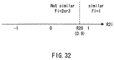
- FIG. 32 is a drawing for describing the relationship between the correlation value for parallax accuracy evaluation and a parallax correction mode flag in the camera module according to Embodiment 3 of the present invention.
- FIG. 33 is a drawing for describing the relationship between a contrast evaluation value for parallax accuracy evaluation and the parallax correction mode flag in the camera module according to Embodiment 3 of the present invention.
- FIG. 34 is a flowchart showing an operation of a parallax correcting portion for low correlation according to Embodiment 3 of the present invention.
- FIG. 35A shows an original image for describing an edge detection of the parallax correcting portion for low correlation of the camera module according to Embodiment 3 of the present invention
- FIG. 35B shows an image of a contrast evaluation value for edge detection for describing the edge detection of the parallax correcting portion for low correlation of the camera module according to Embodiment 3 of the present invention
- FIG. 35C shows an image of edges for describing the edge detection of the parallax correcting portion for low correlation of the camera module according to Embodiment 3 of the present invention.
- FIG. 36 is a sectional view showing a configuration of a camera module according to Embodiment 4 of the present invention.
- FIG. 37 is a block diagram showing the camera module according to Embodiment 4 of the present invention.
- FIGS. 38A to 38D are drawings for describing field images of the camera module according to Embodiment 4 of the present invention.
- FIG. 39 is a flowchart showing an operation of the camera module according to Embodiment 4 of the present invention.
- FIG. 40 is a timing chart showing the operation of the camera module according to Embodiment 4 of the present invention.
- FIGS. 41A to 41C are plan views schematically showing preferable arrangement examples of color filters in the camera module according to Embodiment 4 of the present invention.
- FIG. 42 is a sectional view showing a configuration of a camera module according to Embodiment 5 of the present invention.
- FIG. 43 is a block diagram showing the camera module according to Embodiment 5 of the present invention.
- FIG. 44 is a flowchart showing an operation of the camera module according to Embodiment 5 of the present invention.
- FIGS. 45A to 45C are drawings for describing a background replacement in the camera module according to Embodiment 5 of the present invention.
- FIGS. 46A and 46B illustrate an example of an electronic apparatus according to Embodiment 6 of the present invention.
- FIG. 47 is a sectional view showing a configuration of a conventional camera module (described in JP 2001-78213 A).
- FIG. 48 illustrates an example of an image taken by a conventional camera module (described in JP 2002-330332 A).
- a camera module includes a plurality of lens portions, each including at least one lens, a plurality of imaging regions, provided in one-to-one correspondence with the plurality of lens portions, each including a light-receiving surface that is substantially orthogonal to an optical axis direction of its corresponding lens portion, an imaging signal input portion to which a plurality of imaging signals outputted respectively from the plurality of imaging regions are inputted, a block division portion for dividing at least one imaging signal of the plurality of imaging signals into a plurality of blocks, a parallax computing portion for computing for each of the blocks a parallax between images formed respectively by the plurality of lens portions using the imaging signal, and a parallax correcting portion for correcting the plurality of imaging signals based on the parallax and performing an image synthesis.
- the position of an object image varies relative to a subject distance.
- a parallax increases with decreasing subject distance.
- the parallaxes for the individual subjects are different.
- the parallax is computed for each block, an imaging signal is corrected based on this parallax for each block so as to reduce a parallactic influence, and then an image synthesis is performed. In this manner, even when a plurality of subjects at different distances are shot at the same time, it is possible to correct the parallaxes of the individual subjects suitably, thereby achieving a beautiful image with reduced parallactic influence over an entire image region.
- the above-described camera module according to the present invention further includes an actuator for changing a relative distance between the plurality of lens portions and the plurality of imaging regions, and a focusing control portion for controlling the actuator based on the parallax.
- the actuator is operated based on the parallax so as to carry out an automatic focusing control, so that a focus can be achieved with a single actuator operation. Therefore, it is possible to perform an automatic focusing control at a high speed.
- the above-described camera module according to the present invention further includes a contrast computing portion for computing a contrast based on at least one imaging signal of the plurality of imaging signals and that the focusing control portion controls the actuator based on the parallax and the contrast.
- the focusing control portion controls the actuator plural times, and the actuator is controlled based on the parallax first and based on the contrast thereafter.
- the actuator is operated based on the parallax so as to carry out an automatic focusing control.
- the actuator is operated based on the contrast so as to carry out an automatic focusing control.
- the automatic focusing control based on the parallax is performed at a high speed, because the focus is achieved by a single actuator operation.
- the automatic focusing control based on the contrast is not susceptible to variations of the actuator and thus is highly accurate, because the focus achievement is judged directly from the image.
- the focusing control portion learns an operation amount with respect to the actuator when the actuator is controlled based on the contrast.
- the block division portion divides the at least one imaging signal into the plurality of blocks by detecting outlines of a plurality of image regions from the at least one imaging signal and dividing the at least one imaging signal into the plurality of image regions by the outlines.
- the outlines are detected, the division into blocks is carried out, the imaging signal is corrected so as to reduce a parallactic influence based on the parallax for each block, and then the image synthesis is performed.
- This allows a suitable division into blocks, making it possible to achieve a beautiful image with reduced parallactic influence over the entire image region.
- an outline parallax computing portion is added for computing an outline parallax, which is a parallax between the outlines, based on the imaging signal, and the parallax computing portion computes for each of the blocks the parallax between the images formed respectively by the plurality of lens portions based on the outline parallax.
- the parallax of the outlines is detected. Based on this parallax, a parallax is computed for each block. Based on this parallax, the imaging signal is corrected so as to reduce the parallactic influence, and then the image synthesis is performed. Thus, it is possible to achieve a beautiful image with reduced parallactic influence over the entire image region.
- the block division portion divides the at least one imaging signal into a plurality of rectangular blocks.
- a parallax of a parallax is computed for each block. Based on this parallax, the imaging signal is corrected so as to reduce the parallactic influence, and then the image synthesis is performed. Thus, it is possible to achieve a beautiful image with reduced parallactic influence over the entire image region.
- the above-described camera module according to the present invention further includes a parallax evaluation value computing portion for computing for each of the plurality of blocks at least one parallax accuracy evaluation value indicating an accuracy of the parallax based on the imaging signal, and that the parallax correcting portion corrects for each of the plurality of blocks the plurality of imaging signals based on the parallax and the parallax accuracy evaluation value and performs the image synthesis.
- a divided block sometimes contains a plurality of objects at different subject distances.
- the parallaxes for the individual objects are different.
- the accuracy of the parallax computed for each block is judged, and the method for correcting the imaging signal is modified based on this accuracy. In this manner, it is possible to correct an image by an optimal correction method for each block, thereby achieving a beautiful image with further reduced parallactic influence over the entire image region.
- the parallax correcting portion determines for each of the plurality of blocks whether or not this block is to be divided into at least two based on the parallax accuracy evaluation value and performs the image synthesis based on a parallax between divided blocks in the block determined to be divided.
- the accuracy of the parallax computed for each block is judged, and the block with little accuracy is considered to have mixed parallaxes and divided into at least two blocks. In this manner, it always is possible to correct an image by an optimal block size, thereby achieving a beautiful image with further reduced parallactic influence over the entire image region.
- the parallax evaluation value computing portion computes a first parallax accuracy evaluation value indicating how high a contrast is for each of the plurality of blocks based on at least one imaging signal of the plurality of imaging signals.
- the accuracy of the parallax computed for each block is computed and evaluated based on the contrast, and the method for correcting the imaging signal is modified based on this contrast. In this manner, it is possible to correct an image by an optimal correction method for each block, thereby achieving a beautiful image with further reduced parallactic influence over the entire image region.
- the parallax evaluation value computing portion computes a second parallax accuracy evaluation value indicating how much images formed respectively by at least two of the lens portions and images shifted therefrom by the parallax are correlated for each of the plurality of blocks using the imaging signal divided into the plurality of blocks.
- the accuracy of the parallax computed for each block is computed and evaluated using the second parallax accuracy evaluation value indicating how much an image shifted by the parallax is correlated with the original image, and the method for correcting the imaging signal is modified based on the correlation.
- the method for correcting the imaging signal is modified based on the correlation.
- the parallax correcting portion divides this block into at least two when the second parallax accuracy evaluation value is small, and performs the image synthesis based on the parallax between the divided blocks in the block that has been divided.
- the accuracy of the parallax computed for each block is evaluated using the second parallax accuracy evaluation value indicating how much an image shifted by the parallax is correlated with the original image. Then, the block that is judged to have a small second parallax accuracy evaluation value, namely, a low correlation is divided into at least two blocks. In this manner, it always is possible to correct an image by an optimal block size, thereby achieving a beautiful image with further reduced parallactic influence over the entire image region.
- the parallax evaluation value computing portion computes a first parallax accuracy evaluation value indicating how high a contrast is for each of the plurality of blocks based on at least one imaging signal of the plurality of imaging signals, and a second parallax accuracy evaluation value indicating how much images formed respectively by at least two of the lens portions and images shifted therefrom by the parallax are correlated for each of the plurality of blocks using the imaging signal divided into the plurality of blocks, and for each of the plurality of blocks, the parallax correcting portion divides this block into at least two when the first parallax accuracy evaluation value is large and the second parallax accuracy evaluation value is small, and performs the image synthesis based on the parallax between the divided blocks in the block that has been divided.
- the accuracy of the computed parallax is evaluated using the first parallax accuracy evaluation value indicating how high a contrast is for each block and the second parallax accuracy evaluation value indicating how much an image shifted by the parallax is correlated with the original image.
- the block that is judged to have a large first parallax accuracy evaluation value, namely, a high contrast and a small second parallax accuracy evaluation value, namely, a low correlation is divided into at least two blocks. In this manner, it always is possible to correct an image by an optimal block size, thereby achieving a beautiful image with further reduced parallactic influence over the entire image region.
- the imaging signal input portion inputs the plurality of imaging signals for each of a plurality of fields
- the parallax computing portion computes the parallax for each of the blocks in each of the plurality of fields.
- the above-described preferable configuration further includes color filters that are provided in one-to-one correspondence with the plurality of lens portions and have filters of plural colors, and that the filters of the same color are provided so as to correspond to at least two of the plurality of lens portions arranged in parallel with a scanning direction of the fields.
- the above-described camera module according to the present invention further includes another image storing portion for storing another image different from a taken image, and that the parallax correcting portion combines the another image and an image obtained by correcting the imaging signal based on the parallax.
- the parallax correcting portion performs combining so that a ratio of the image obtained by correcting the imaging signal increases and that of the another image decreases with an increase in the parallax.
- an electronic apparatus includes the above-described camera module of the present invention.
- a program according to the present invention is a program for controlling an operation of an image processing portion in a camera module including a plurality of lens portions, each including at least one lens, a plurality of imaging regions, provided in one-to-one correspondence with the plurality of lens portions, each including a light-receiving surface that is substantially orthogonal to an optical axis direction of its corresponding lens portion, an imaging signal input portion to which a plurality of imaging signals outputted respectively from the plurality of imaging regions are inputted, and the image processing portion for performing an image processing of the inputted imaging signal.
- the program causes the image processing portion to execute a block division process of dividing at least one imaging signal of the plurality of imaging signals into a plurality of blocks, a parallax computing process of computing for each of the blocks a parallax between images formed respectively by the plurality of lens portions using the imaging signal, and a parallax correcting process of correcting the plurality of imaging signals based on the parallax and performing an image synthesis.
- a program recording medium is a computer-readable program recording medium storing the above-described program.
- the parallax is computed for each block, an imaging signal is corrected based on this parallax for each block so as to reduce a parallactic influence, and then an image synthesis is performed.
- an imaging signal is corrected based on this parallax for each block so as to reduce a parallactic influence
- an image synthesis is performed.
- a camera module achieves a beautiful image over an entire image region by detecting edges, performing a division into blocks and performing a parallax correction based on the parallax for each block. Also, by making a coarse adjustment by an automatic focusing control based on the parallax and a fine adjustment by an automatic focusing control based on a highly accurate contrast, it is possible to carry out a highly accurate automatic focusing control at a high speed. Furthermore, an amount of the fine adjustment is learned so as to improve the accuracy of the next coarse adjustment.
- FIG. 1 is a sectional view showing a configuration of the camera module according to Embodiment 1 of the present invention.
- a camera module 101 includes a lens module portion 110 and a circuit portion 120 .
- the lens module portion 110 includes a barrel 111 , an upper cover glass 112 , a lens 113 , an actuator fixing portion 114 and an actuator movable portion 115 .
- the circuit portion 120 includes a substrate 121 , a package 122 , an imaging device 123 , a package cover glass 124 and a system LSI (hereinafter, referred to as an SLSI) 125 .
- the barrel 111 has a cylindrical shape with its inner wall surface being matte black for preventing light diffusion, and is formed by injection molding of a resin.
- the upper cover glass 112 has a disc shape, is formed of a transparent resin and fixed firmly to an upper surface of the barrel 111 with an adhesive or the like.
- the surface of the upper cover glass 112 is provided with a protective film for preventing damage due to friction or the like and an antireflection film for preventing reflection of incident light.
- FIG. 2 is a top view showing the lens 113 of the camera module according to Embodiment 1 of the present invention.
- the lens 113 has a substantially disc shape, is formed of glass or a transparent resin and provided with a first lens portion 113 a , a second lens portion 113 b , a third lens portion 113 c and a fourth lens portion 113 d that are arranged in a lattice pattern.
- an X axis and a Y axis are set along the arrangement directions of the first to fourth lens portions 113 a to 113 d .
- first lens portion 113 a In the first lens portion 113 a , the second lens portion 113 b , the third lens portion 113 c and the fourth lens portion 113 d , light entering from a subject side leaves for a side of the imaging device 123 and forms four images on the imaging device 123 .
- the actuator fixing portion 114 is fixed firmly to the inner wall surface of the barrel 111 with an adhesive or the like.
- the actuator movable portion 115 is fixed firmly to an outer peripheral edge of the lens 113 with an adhesive or the like.
- the actuator fixing portion 114 and the actuator movable portion 115 constitute a voice coil motor.
- the actuator fixing portion 114 has a permanent magnet (not shown) and a ferromagnetic yoke (not shown), and the actuator movable portion 115 has a coil (not shown).
- the actuator movable portion 115 is supported elastically by an elastic member (not shown) with respect to the actuator fixing portion 114 . By passing an electric current through the coil of the actuator movable portion 115 , the actuator movable portion 115 moves relatively to the actuator fixing portion 114 , so that the relative distance between the lens 113 and the imaging device 123 along an optical axis varies.
- the substrate 121 is made of a resin substrate, and the barrel 111 is fixed firmly to an upper surface of the substrate 121 with an adhesive or the like such that a bottom surface of the barrel 111 contacts the upper surface of the substrate 121 . In this way, the lens module portion 110 and the circuit portion 120 are fixed to each other, thus forming the camera module 101 .
- the package 122 is formed of a resin having metal terminals. Inside the barrel 111 , the package 122 is fixed firmly to the upper surface of the substrate 121 with its metal terminal portion being fixed by soldering or the like.
- the imaging device 123 is constituted by a first imaging device 123 a , a second imaging device 123 b , a third imaging device 123 c and a fourth imaging device 123 d .
- Each of the first imaging device 123 a , the second imaging device 123 b , the third imaging device 123 c and the fourth imaging device 123 d is a solid-state imaging device such as a CCD sensor or a CMOS sensor.
- Individual terminals of the first imaging device 123 a , the second imaging device 123 b , the third imaging device 123 c and the fourth imaging device 123 d are connected to the metal terminals in the bottom portion inside the package 122 with metal wires 127 by wire bonding and connected electrically to the SLSI 125 via the substrate 121 .
- Light that has left the first lens portion 113 a , light that has left the second lens portion 113 b , light that has left the third lens portion 113 c and light that has left the fourth lens portion 113 d respectively form images on the light-receiving surfaces of the first imaging device 123 a , the second imaging device 123 b , the third imaging device 123 c and the fourth imaging device 123 d .
- Electric information converted from optical information by photodiodes is outputted to the SLSI 125 .
- FIG. 3 is a top view showing the circuit portion 120 of the camera module according to Embodiment 1 of the present invention.
- the package cover glass 124 has a flat shape, is formed of a transparent resin and fixed firmly to the upper surface of the package 122 by adhesion or the like.
- An upper surface of the package cover glass 124 is provided with a first color filter 124 a , a second color filter 124 b , a third color filter 124 c , a fourth color filter 124 d and a shielding portion 124 e by deposition or the like.
- a lower surface of the package cover glass 124 is provided with an infrared ray shielding filter (not shown; hereinafter, referred to as an IR filter) by deposition or the like.
- FIG. 4 shows characteristics of the color filters of the camera module according to Embodiment 1 of the present invention
- FIG. 5 shows characteristics of the IR filter of the camera module according to Embodiment 1 of the present invention
- the first color filter 124 a has spectral transmittance characteristics mainly transmitting green indicated by G in FIG. 4
- the second color filter 124 b has spectral transmittance characteristics mainly transmitting blue indicated by B in FIG. 4
- the third color filter 124 c has spectral transmittance characteristics mainly transmitting red indicated by R in FIG. 4
- the fourth color filter has spectral transmittance characteristics mainly transmitting green indicated by G in FIG. 4
- the IR filter has spectral transmittance characteristics blocking infrared rays indicated by IR in FIG. 5 .
- object light that has entered from an upper portion of the first lens portion 113 a leaves a lower portion of the first lens portion 113 a , and its green component mainly is transmitted by the first color filter 124 a and the IR filter so as to form an image on the light-receiving portion of the first imaging device 123 a , and therefore, the first imaging device 123 a receives the green component of the object light.
- Object light that has entered from an upper portion of the second lens portion 113 b leaves a lower portion of the second lens portion 113 b , and its blue component mainly is transmitted by the second color filter 124 b and the IR filter so as to form an image on the light-receiving portion of the second imaging device 123 b , and therefore, the second imaging device 123 b receives the blue component of the object light.
- Object light that has entered from an upper portion of the third lens portion 113 c leaves a lower portion of the third lens portion 113 c , and its red component mainly is transmitted by the third color filter 124 c and the IR filter so as to form an image on the light-receiving portion of the third imaging device 123 c , and therefore, the third imaging device 123 c receives the red component of the object light.
- object light that has entered from an upper portion of the fourth lens portion 113 d leaves a lower portion of the fourth lens portion 113 d , and its green component mainly is transmitted by the fourth color filter 124 d and the IR filter so as to form an image on the light-receiving portion of the fourth imaging device 123 d , and therefore, the fourth imaging device 123 d receives the green component of the object light.
- the SLSI 125 controls the passage of an electric current through the coil of the actuator movable portion 115 , drives the imaging device 123 , inputs the electric information from the imaging device 123 , carries out various image processings, communicates with a main CPU and outputs an image to an external part, by a method described later.
- the camera module according to Embodiment 1 of the present invention has four lens portions (the first lens portion 113 a , the second lens portion 113 b , the third lens portion 113 c and the fourth lens portion 113 d ), the relative positions of the four object images formed respectively by these four lens portions vary according to the subject distance.
- FIG. 6 is a drawing for describing positions of images of an object at an infinite distance in the camera module according to Embodiment 1 of the present invention.
- FIG. 6 shows only the first lens portion 113 a , the first imaging device 123 a , the second lens portion 113 b and the second imaging device 123 b .
- Incident light L 1 into the first lens portion 113 a from an object 10 at an infinite distance and incident light L 2 into the second lens portion 113 b therefrom are in parallel. Accordingly, the distance between the first lens portion 113 a and the second lens portion 113 b and that between an object image 11 a on the first imaging device 123 a and an object image 11 b on the second imaging device 123 b are equal.
- the optical axes of the first lens portion 113 a , the second lens portion 113 b , the third lens portion 113 c and the fourth lens portion 113 d substantially match the centers of the light-receiving surfaces of the first imaging device 123 a , the second imaging device 123 b , the third imaging device 123 c and the fourth imaging device 123 d , respectively.
- the relative positional relationships between the centers of the respective light-receiving surfaces of the first imaging device 123 a , the second imaging device 123 b , the third imaging device 123 c and the fourth imaging device 123 d and respective images of the object at an infinite distance formed on these light-receiving surfaces are the same for all the imaging devices. In other words, there is no parallax.
- FIG. 7 is a drawing for describing positions of images of an object at a finite distance in the camera module according to Embodiment 1 of the present invention.
- FIG. 7 shows only the first lens portion 113 a , the first imaging device 123 a , the second lens portion 113 b and the second imaging device 123 b .
- Incident light L 1 into the first lens portion 113 a from an object 12 at a finite distance and incident light L 2 into the second lens portion 113 b therefrom are not in parallel.
- the distance between an object image 13 a on the first imaging device 123 a and an object image 13 b on the second imaging device 123 b is greater than that between the first lens portion 113 a and the second lens portion 113 b .
- the relative positional relationships between the centers of the respective light-receiving surfaces of the first imaging device 123 a , the second imaging device 123 b , the third imaging device 123 c and the fourth imaging device 123 d and respective images of the object at a finite distance formed on these light-receiving surfaces are different from one imaging device to another. In other words, there is a parallax.
- FIG. 8A is a drawing for describing the relationship between an image when a focus is achieved (a focus is adjusted) and a contrast evaluation value in the camera module according to Embodiment 1 of the present invention
- FIG. 8B is a drawing for describing the relationship between the image when the focus is not achieved (the focus is not adjusted) and the contrast evaluation value in the camera module according to Embodiment 1 of the present invention.
- FIGS. 8A and 8B show images when shooting a rectangle whose left half is white and right half is black.
- an outline of the image is clear, resulting in a high contrast.
- the outline of the image is blurred, resulting in a low contrast.
- FIGS. 8A and 8B show results of subjecting information signals of the left-hand drawings to a band-pass filter (BPF).
- BPF band-pass filter
- the horizontal axis indicates a position in an X-axis direction
- the vertical axis indicates an output value after BPF.
- a signal amplitude after BPF is large when the focus is achieved.
- the signal amplitude after BPF is small when the focus is not achieved.
- the signal amplitude after BPF is defined as a contrast evaluation value indicating how high the contrast is. Then, the contrast evaluation value is large when the focus is achieved as shown in the drawing on the right in FIG. 8A , whereas the contrast evaluation value is small when the focus is not achieved as shown in the drawing on the right in FIG. 8B .
- FIG. 9 is a drawing for describing the relationship between a lens position and the contrast evaluation value in the camera module according to Embodiment 1 of the present invention.
- FIG. 10 is a block diagram showing the camera module according to Embodiment 1 of the present invention.
- the SLSI 125 includes a system control portion 131 , an imaging device driving portion 132 , an imaging signal input portion 133 , an actuator operation amount output portion 134 , an image processing portion 135 and an input/output portion 136 .
- the circuit portion 120 includes an amplifier 126 in addition to the configuration described above.
- the amplifier 126 applies a voltage according to an output from the actuator operation amount output portion 134 to the coil of the actuator movable portion 115 .
- the system control portion 131 is configured by a CPU (central processing unit), a memory, etc. and controls the entire SLSI 125 .
- the imaging device driving portion 132 is configured by a logic circuit, etc., generates a signal for driving the imaging device 123 and applies a voltage according to this signal to the imaging device 123 .
- the imaging signal input portion 133 includes a first imaging signal input portion 133 a , a second imaging signal input portion 133 b , a third imaging signal input portion 133 c and a fourth imaging signal input portion 133 d .
- the first imaging signal input portion 133 a , the second imaging signal input portion 133 b , the third imaging signal input portion 133 c and the fourth imaging signal input portion 133 d are each configured by connecting a CDS circuit (correlated double sampling circuit), an AGC (automatic gain controller) and an ADC (analog digital converter) in series.
- CDS circuit correlated double sampling circuit
- AGC automatic gain controller
- ADC analog digital converter
- the first imaging device 123 a , the second imaging device 123 b , the third imaging device 123 c and the fourth imaging device 123 d are connected to the first imaging device 123 a , the second imaging device 123 b , the third imaging device 123 c and the fourth imaging device 123 d , respectively, supplied with electric signals from them, remove fixed noises with the CDS circuit, adjust gains with the AGC, convert analog signals into digital values with the ADC and write them into the memory in the system control portion 131 .
- the actuator operation amount output portion 134 is configured by a DAC (digital analog converter) and outputs a voltage signal according to a voltage to be applied to the coil of the actuator movable portion 115 .
- the image processing portion 135 is configured so as to include a logic circuit, a DSP or both of the logic circuit and the DSP and carries out various image processings utilizing memory information in the system control portion 131 according to a predetermined program control.
- the image processing portion 135 includes an edge detecting portion 141 , a block division portion 142 , a parallax computing portion 143 , a parallax correcting portion 144 , a parallax-based automatic focusing control portion 145 , an actuator control portion 146 , a contrast-based automatic focusing control portion 147 , a portion 148 for computing a contrast evaluation value for automatic focusing control and an actuator operation amount function correcting portion 149 .
- the input/output portion 136 communicates with the main CPU (not shown) and outputs an image signal to the main CPU, an external memory (not shown) and an external display (not shown) such as a liquid crystal display.
- FIG. 11 is a flowchart showing the operation of the camera module according to Embodiment 1 of the present invention.
- the camera module 101 is operated as per this flowchart by the system control portion 131 of the SLSI 125 .
- Step S 100 the operation starts.
- the main CPU (not shown) senses that a shutter button or the like is pressed down, and instructs the camera module to start operating via the input/output portion 136 , whereby the camera module 101 starts operating.
- Step S 110 is executed.
- Step S 110 shooting is executed.
- the imaging device driving portion 132 outputs signals for an electronic shutter and transferring as necessary.
- the first imaging signal input portion 133 a , the second imaging signal input portion 133 b , the third imaging signal input portion 133 c and the fourth imaging signal input portion 133 d input imaging signals, which are analog signals of the images outputted respectively by the first imaging device 123 a , the second imaging device 123 b , the third imaging device 123 c and the fourth imaging device 123 d , in synchronization with the signals generated by the imaging device driving portion 132 , remove fixed noises with the CDS, adjust input gains automatically with the AGC, convert the analog signals into digital values with the ADC, and write the digital values into the memory at a predetermined address in the system control portion 131 as a first imaging signal I 1 ( x,y ), a second imaging signal I 2 ( x,y ), a third imaging signal I 3 ( x,y ) and
- FIG. 12 is a drawing for describing coordinates of the imaging signal of the camera module according to Embodiment 1 of the present invention.
- I 1 ( x,y ) indicates the first imaging signal, which is the x-th signal in a horizontal direction and the y-th signal in a vertical direction.
- the number of pixels in the vertical direction is H
- the number of pixels in the horizontal direction is L
- the total number of pixels is H ⁇ L.
- x varies from 0 to L ⁇ 1
- y varies from 0 to H ⁇ 1. This also holds true for the second imaging signal I 2 ( x,y ), the third imaging signal I 3 ( x,y ) and the fourth imaging signal I 4 ( x,y ).
- I 2 ( x,y ), I 3 ( x,y ) and I 4 ( x,y ) respectively indicate the second imaging signal, the third imaging signal and the fourth imaging signal, each of which is the x-th signal in the horizontal direction and the y-th signal in the vertical direction.
- the number of pixels in the vertical direction is H
- the number of pixels in the horizontal direction is L
- the total number of pixels is H ⁇ L.
- x varies from 0 to L ⁇ 1
- y varies from 0 to H ⁇ 1.
- Step S 121 and Step S 122 the edge detecting portion 141 utilizes data in the memory in the system control portion 131 and detects edges. Then, the edge detecting portion 141 writes the result into the memory in the system control portion 131 . A detail will be described in the following.
- Step S 121 a contrast evaluation value for edge detection is computed. This computation is performed only for the first imaging signal. Laplacian is computed as per Equation (2) below and further is subjected spatially to a LPF (low-pass filter) as per Equation (3) below, and the result is given as a contrast evaluation value for edge detection C 2 ( x,y ).
- FIG. 13A shows an original image for describing the edge detection of the camera module according to Embodiment 1 of the present invention
- FIG. 13B shows an image of the contrast evaluation value for edge detection for describing the edge detection of the camera module according to Embodiment 1 of the present invention. From Equations (2) and (3), the contrast evaluation value for edge detection C 2 ( x,y ) of the original image in FIG.
- Step S 122 is executed.
- C 1( x,y ) I 1( x ⁇ 1 ,y )+ I 1( x+ 1 ,y )+ I 1( x,y ⁇ 1)+ I 1( x,y+ 1) ⁇ 4 I 1( x,y ) (2)
- C ⁇ ⁇ 2 ⁇ ( x , y ) C ⁇ ⁇ 1 ⁇ ( x - 1 , y - 1 ) + C ⁇ ⁇ 1 ⁇ ( x , y - 1 ) + C ⁇ ⁇ 1 ⁇ ( x + 1 , y - 1 ) + C ⁇ ⁇ 1 ⁇ ( x - 1 , y ) + C ⁇ ⁇ 1 ⁇ ( x + 1 , y ) + C ⁇ ⁇ 1 ⁇ ( x + 1 , y ) + C ⁇ ⁇ 1 ⁇ ( x + 1 , y + 1 ) + C ⁇ ⁇ 1 ⁇ ( x - 1 , y + 1 ) + C ⁇ ⁇ 1 ⁇ ( x , y + 1 ) + C ⁇ ⁇ 1 ⁇ ( x + 1 , y + 1 ) ( 3 )
- Step S 122 the edges are detected.
- FIG. 13C shows an image of the edges for describing the edge detection of the camera module according to Embodiment 1 of the present invention.
- a zero crossing a point at which a value changes from positive to negative and a point at which a value changes from negative to positive
- Step S 130 is executed.
- Step S 130 the block division portion 142 utilizes data in the memory in the system control portion 131 and carries out a division into blocks. Then, the block division portion 142 writes the result into the memory in the system control portion 131 .
- numbers such as B 0 , B 1 , . . . , Bi, . . . , Bn are given to regions surrounded by the edges. Incidentally, in order to prevent erroneous detection and loss of the edges due to noise or the like, the edges also may be corrected using a dilation algorithm or an erosion algorithm.
- Step S 140 is executed.
- Step S 140 the parallax computing portion 143 utilizes data in the memory in the system control portion 131 and computes a parallax value for each block. Then, the parallax computing portion 143 writes the parallax value into the memory in the system control portion 131 .
- a region indicated by Bi (also indicated by I 1 ) is the i-th block obtained from the first imaging signal I 1 in Step S 130 .
- a region indicated by I 4 is a region obtained by moving Bi by k in an x direction and k in a y direction. Then, for all image signals I 1 ( x,y ) and I 4 ( x,y ) in these regions, the sum of absolute difference expressed by Equation (4) below is computed as a parallax evaluation value Ri(k).
- Ri ( k ) ⁇
- This parallax evaluation value Ri(k) indicates how the first image signal I 1 of the i-th block B 1 and the fourth image signal I 4 in the region shifted therefrom by (k, k) respectively in the x and y directions are correlated.
- Step S 151 is executed.
- Step S 151 and Step S 152 a preview image is outputted.
- Step S 151 the parallax correcting portion 144 utilizes data in the memory in the system control portion 131 , carries out a parallax correction for each block using the parallax value corresponding to this block, and then performs an image synthesis. Then, the parallax correcting portion 144 writes the result into the memory in the system control portion 131 . Since the first imaging device 123 a and the fourth imaging device 123 d mainly receive the green component of the object light, the first imaging signal I 1 and the fourth imaging signal I 4 are information signals of the green component of the object light. Also, since the second imaging device 123 b mainly receives the blue component of the object light, the second imaging signal I 2 is an information signal of the blue component of the object light.
- the third imaging signal 123 c mainly receives the red component of the object light
- the third imaging signal I 3 is an information signal of the red component of the object light. Since the parallax between the first imaging device 123 a and the fourth imaging device 123 d is calculated to be ( ⁇ i, ⁇ i), G(x,y) indicating the intensity of green at the pixel coordinates (x,y) is given by an average of the first imaging signal I 1 ( x,y ) and the fourth imaging signal I 4 ( x ⁇ i,y ⁇ i ) as in Equation (5) below.
- the parallax between the first imaging device 123 a and the second imaging device 123 b is calculated to be ( ⁇ i, 0)
- B(x,y) indicating the intensity of blue at the pixel coordinates (x,y) is given by the second imaging signal I 2 ( x ⁇ i,y ) as in Equation (6) below.
- R(x,y) indicating the intensity of red at (x,y) is given by the third imaging signal I 3 ( x,y ⁇ i ) as in Equation (7) below.
- Step S 152 is executed.
- G ( x,y ) [ I 1( x,y )+ I 4( x ⁇ i,y ⁇ i )]/2 (5)
- B ( x,y ) I 2( x ⁇ i,y ) (6)
- R ( x,y ) I 3( x,y ⁇ i ) (7)
- Step S 152 an image is outputted.
- the input/output portion 136 outputs G(x,y), B(x,y) and R(x,y), which are data in the memory in the system control portion 131 , to the main CPU (not shown) and the external display (not shown).
- a luminance signal or a color difference signal may be outputted instead of G(x,y), B(x,y) and R(x,y).
- values after the image processings such as a white-balance correction and a ⁇ correction may be outputted.
- S 161 is executed.
- Steps S 161 , S 162 and S 163 , and S 164 an automatic focusing control is carried out using the parallax value.
- Step 161 the parallax-based automatic focusing control portion 145 selects a block for automatic focusing control based on the data in the memory in the system control portion 131 . Then, the parallax-based automatic focusing control portion 145 writes the result into the memory in the system control portion 131 .
- at least one block for example, three blocks Bj 1 , Bj 2 and Bj 3 ) near the center of the image region is selected. Incidentally, these blocks do not have to be the ones near the center but may be the ones selected by reflecting an intention of a user operating the camera (for example, by detecting a viewpoint direction with a sensor).
- Step S 162 is executed.
- Step S 162 a positional instruction of the actuator is computed.
- an average of the parallax values ⁇ j 1 , ⁇ j 2 and ⁇ j 3 of the blocks Bj 1 , Bj 2 and Bj 3 serves as a parallax value for automatic focusing control ⁇ af as in Equation (8) below.
- weights may be assigned suitably by information such as how large the areas of the blocks are or whether the blocks are close to the center.
- a positional instruction Xact of the actuator is computed.
- the positional instruction Xact indicates an instruction of a position in a direction toward the subject with respect to the position at which an infinity object is focused.
- Step S 163 is executed.
- ⁇ af ( ⁇ j 1 + ⁇ j 2 + ⁇ j 3)/3 (8)
- X act kx ⁇ af (9)
- Step S 163 the actuator control portion 146 computes an actuator operation amount (a voltage to be applied to the coil of the actuator movable portion 115 ) Vact using an operation amount function expressed by Equation (10) below. Also, the actuator control portion 146 stores the actuator operation amount as Vact 0 for learning an operation amount function as described later.
- Step S 164 is executed.
- V act ka ⁇ X act+ kb (10)
- Vact0 Vact (10′)
- Step S 164 the actuator is operated.
- the actuator operation amount output portion 134 changes a voltage signal to be outputted so that a voltage applied to the coil (not shown) of the actuator movable portion 115 via the amplifier 126 is Vact.
- Step S 171 is executed.
- the contrast-based automatic focusing control portion 147 carries out an automatic focusing control using the contrast.
- the contrast evaluation value is at a maximum at the position where the focus is achieved. Using this principle, a search is made for an actuator operation amount with which the contrast evaluation value becomes maximal.
- Step S 171 a contrast evaluation value for automatic focusing control without a correction of the actuator operation amount is created.
- Step S 171 includes Step S 171 c and Step S 171 d .
- Step S 171 c is executed.
- Step S 171 c shooting is executed. This operation is similar to that in Step S 110 . However, it may be possible to transfer only the imaging signal I 1 of the block for automatic focusing control selected in S 161 out of the imaging signals I 1 from the first imaging device 123 a . In this case, a transfer time can be shortened compared with the case of transferring all the imaging signals.
- Step S 171 d is executed.
- Step S 171 d the portion 148 for computing a contrast evaluation value for automatic focusing control creates a contrast evaluation value for automatic focusing control using the data in the memory in the system control portion 131 .
- This computation is performed only for the first imaging signal I 1 of the block for automatic focusing control.
- An absolute value of Laplacian is computed as per Equation (11) below and further is subjected spatially to a LPF (low-pass filter) as per Equation (12) below, and the result is averaged in the block for automatic focusing control as per Equation (13) below, thereby obtaining a contrast evaluation value for automatic focusing C 5 .
- N represents the number of C 4 ( x,y ) in the block for automatic focusing control.
- the contrast evaluation value C 5 at this time is given as C 50 and written into the memory in the system control portion 131 .
- Step S 172 is executed.
- Step 172 the contrast evaluation value for automatic focusing control at the time of positive correction of the actuator operation amount is created.
- Step S 172 includes Step S 172 a , Step S 172 b , Step S 172 c and Step S 172 d .
- Step S 172 a is executed.
- Step S 172 a an actuator operation amount at the time of positive correction Vact is obtained by adding dVact to the actuator operation amount (the voltage to be applied to the coil of the actuator fixing portion 114 ) without a correction Vact 0 as per Equation (15) below and stored in the memory as Vactp as per Equation (16) below.
- Steps S 172 b , S 172 c and S 172 d are executed.
- V act V act0 +dV act (15)
- Vactp Vact (16)
- Step S 172 b the actuator is operated.
- Step S 172 c shooting is executed.
- Step S 172 d the contrast evaluation value for automatic focusing control is created.
- the operation in Step S 172 b is similar to that in Step S 164 .
- the operations in Steps S 172 c and S 172 d are similar to those in Steps S 171 c and S 171 d .
- the contrast evaluation value C 5 is given as a contrast evaluation value for automatic focusing after positive correction C 5 p as per Equation (17) below and written into the memory in the system control portion 131 .
- Step S 173 is executed.
- C5p C5 (17)
- Step 173 the contrast evaluation value for automatic focusing control at the time of negative correction of the actuator operation amount is created.
- Step S 173 includes Step S 173 a , Step S 173 b , Step S 173 c and Step S 173 d .
- Step S 173 a is executed.
- Step S 173 a an actuator operation amount at the time of negative correction Vact is obtained by subtracting dVact from the actuator operation amount (the voltage to be applied to the coil of the actuator fixing portion 114 ) without a correction Vact 0 as per Equation (18) below and stored in the memory as Vactn as per Equation (19) below.
- Steps S 173 b , S 173 c and S 173 d are executed.
- V act V act0 ⁇ dV act (18)
- Vactn Vact (19)
- Step S 173 b the actuator is operated.
- Step S 173 c shooting is executed.
- Step S 173 d the contrast evaluation value for automatic focusing control is created. The operations similar to those in Step S 172 b , Step S 172 c and Step S 172 d are carried out.
- the contrast evaluation value C 5 is given as a contrast evaluation value for automatic focusing after negative correction C 5 n as per Equation (20) below and written into the memory in the system control portion 131 .
- Step S 174 is executed.
- C5n C5 (20)
- Step S 174 the contrast evaluation values for focusing control are evaluated.
- C 50 , C 5 p and C 5 n are compared, and the operation is branched according to which has the maximum value.
- FIG. 16A is a drawing for describing the relationship between the actuator operation amount and the contrast evaluation value when the contrast evaluation value is at a maximum without correction in the camera module according to Embodiment 1 of the present invention.
- the actuator operation amount without correction Vact 0 gives substantially the maximum value of the contrast evaluation value for automatic focusing control C 5 . Therefore, as in Equation (21) below, Vact 0 serves as a final actuator operation amount Vactf.
- Vactf Vact0(when C50 is the maximum value) (21)
- FIG. 16B is a drawing for describing the relationship between the actuator operation amount and the contrast evaluation value when the contrast evaluation value after positive correction is at a maximum in the camera module according to Embodiment 1 of the present invention.
- the actuator operation amount after positive correction Vactp or the actuator operation amount after a further positive correction Vact gives substantially the maximum value of the contrast evaluation value for automatic focusing control C 5 . Therefore, the actuator operation amount is corrected further toward the positive side, and a search is made for the maximum value.
- Equation (22) Equation (22) below, C 5 p serves as a previous value and is stored as C 5 pp.
- C5pp C5p (22)
- FIG. 16C is a drawing for describing the relationship between the actuator operation amount and the contrast evaluation value when the contrast evaluation value after negative correction is at a maximum in the camera module according to Embodiment 1 of the present invention.
- the actuator operation amount after negative correction Vactn or the actuator operation amount after a further negative correction Vact gives substantially the maximum value of the contrast evaluation value for automatic focusing control C 5 . Therefore, the actuator operation amount is corrected further toward the negative side, and a search is made for the maximum value.
- Equation (23) C 5 n serves as a previous value and is stored as C 5 np.
- Step S 175 the contrast evaluation value for automatic focusing at the time of the further positive correction is created and evaluated.
- Step S 175 includes Step S 175 a , Step S 175 b , Step S 175 c , Step S 175 d and Step S 175 e .
- Step S 175 a is executed.
- Step S 175 a an actuator operation amount at the time of positive correction Vact is obtained by adding dVact to the actuator operation amount (the voltage to be applied to the coil of the actuator fixing portion 114 ) after the previous positive correction Vactp as per Equation (24) below and stored in the memory as Vactp as per Equation (25) below.
- Steps S 175 b , S 175 c and S 175 d are executed.
- V act V act p+dV act (24)
- Vactp Vact (25)
- Step S 175 b the actuator is operated.
- Step S 175 c shooting is executed.
- Step S 175 d the contrast evaluation value for automatic focusing control is created. The operations similar to those in Step 172 b , Step S 172 c and Step S 172 d are carried out.
- the contrast evaluation value C 5 is given as a contrast evaluation value for automatic focusing after positive correction C 5 p as per Equation (26) below and written into the memory in the system control portion 131 .
- Step S 175 e is executed.
- C5p C5 (26)
- Step S 175 e the contrast evaluation values for focusing control are evaluated.
- C 5 pp and C 5 p are compared, and the operation is branched according to which has the maximum value.
- FIG. 17A is a drawing for describing the relationship between the actuator operation amount and the contrast evaluation value when the contrast evaluation value before the further positive correction is at a maximum in the case where this further positive correction is performed in the camera module according to Embodiment 1 of the present invention.
- the actuator operation amount after the previous positive correction Vactp ⁇ dVact gives substantially the maximum value of the contrast value for automatic focusing control C 5 . Therefore, as in Equation (27) below, Vactp ⁇ dVact serves as the final actuator operation amount Vactf.
- V act f V act p ⁇ dV act(when C5 pp is the maximum value) (27)
- FIG. 17B is a drawing for describing the relationship between the actuator operation amount and the contrast evaluation value when the contrast evaluation value after the further positive correction is at a maximum in the case where this further positive correction is performed in the camera module according to Embodiment 1 of the present invention.
- the actuator operation amount after the current positive correction Vactp or the actuator operation amount after a further positive correction Vact gives substantially the maximum value of the contrast evaluation value for automatic focusing control C 5 . Therefore, the actuator operation amount is corrected further toward the positive side, and a search is made for the maximum value.
- Equation (28) Equation (28) below, C 5 p serves as a previous value and is stored as C 5 pp.
- C5pp C5p (28)
- Step S 176 the contrast evaluation value for automatic focusing at the time of the further negative correction is created and evaluated.
- Step S 176 includes Step S 176 a , Step S 176 b , Step S 176 c , Step S 176 d and Step S 176 e .
- Step S 176 a is executed.
- Step S 176 a an actuator operation amount at the time of negative correction Vact is obtained by subtracting dVact from the actuator operation amount (the voltage to be applied to the coil of the actuator fixing portion 114 ) after the previous negative correction Vactn as per Equation (29) below and stored in the memory as Vactn as per Equation (30) below.
- Steps S 176 b , S 176 c and S 176 d are executed.
- V act V act n ⁇ dV act (29)
- Vactn Vact (30)
- Step S 176 b the actuator is operated.
- Step S 176 c shooting is executed.
- Step S 176 d the contrast evaluation value for automatic focusing control is created. The operations similar to those in Step 172 b , Step S 172 c and Step S 172 d are carried out.
- the contrast evaluation value C 5 is given as a contrast evaluation value for automatic focusing after negative correction C 5 n as per Equation (31) below and written into the memory in the system control portion 131 .
- Step S 176 e is executed.
- C5n C5 (31)
- Step S 176 e the contrast evaluation values for focusing control are evaluated.
- C 5 np and C 5 n are compared, and the operation is branched according to which has the maximum value.
- FIG. 18A is a drawing for describing the relationship between the actuator operation amount and the contrast evaluation value when the contrast evaluation value before the further negative correction is at a maximum in the case where this further negative correction is performed in the camera module according to Embodiment 1 of the present invention.
- FIG. 18B is a drawing for describing the relationship between the actuator operation amount and the contrast evaluation value when the contrast evaluation value after the further negative correction is at a maximum in the case where this further negative correction is performed in the camera module according to Embodiment 1 of the present invention.
- the actuator operation amount after the current negative correction Vactn or the actuator operation amount after a further negative correction Vact gives substantially the maximum value of the contrast evaluation value for automatic focusing control C 5 . Therefore, the actuator operation amount is corrected further toward the negative side, and a search is made for the maximum value.
- Equation (33) C 5 n serves as a previous value and is stored as C 5 np.
- C5np C5n (33)
- Steps S 181 , S 182 , S 183 , S 184 and S 185 a final shooting and an image output are performed.
- Step S 181 as in Equation (34) below, the final actuator operation amount Vactf obtained above is set as the actuator operation amount Vact.
- Step S 182 is executed.
- Vact Vactf (34)
- Step S 182 the actuator is operated.
- the operation in this step is similar to that in Step S 164 .
- Step S 183 is executed.
- Step S 183 shooting is performed.
- the operation in this step is similar to that in Step S 110 .
- Step S 184 is executed.
- Step S 184 a parallax correction is carried out for each block using the parallax value corresponding to this block, and then an image synthesis is performed.
- the operation in this step is similar to that in Step S 151 .
- Step S 185 is executed.
- Step S 185 an image is outputted.
- the operation in this step is similar to that in S 152 .
- Step S 190 is executed.
- Step S 190 the actuator operation amount function correcting portion 149 corrects an operation amount function based on a correction value for a contrast-based automatic focusing control.
- a coefficient kb of the operation amount function is corrected as per Equation (35) below so as to change a value written in the memory in the system control portion 131 . This value is used at the time of the next shooting.
- Step S 199 the processing ends.
- the actuator positional instruction Xact is created based on the parallax value ⁇ af for automatic focusing control, the actuator operation amount Vact is computed, and a voltage is applied to the coil of the actuator fixing portion 114 so as to operate the actuator, thereby carrying out the automatic focusing control. In this manner, a focus is achieved by a single actuator operation, thus allowing a high-speed automatic focusing control.
- Steps S 161 , S 162 , S 163 and S 164 the actuator is operated based on the parallax so as to carry out the automatic focusing control.
- Steps S 171 , S 172 , S 173 , S 174 , S 175 and S 176 the actuator is operated based on the contrast so as to carry out the automatic focusing control.
- the automatic focusing control based on the parallax is performed at a high speed, because the focus is achieved by a single actuator operation.
- the automatic focusing control based on the contrast is not susceptible to variations of the actuator and thus is highly accurate, because the focus achievement is judged directly from the image.
- Step S 190 learning is conducted so as to correct the coefficient kb of the operation amount function based on the actuator operation amount (Vactf ⁇ Vact 0 ) corrected in the contrast-based automatic focusing control.
- This makes it possible to correct the operation amount function in a more accurate manner even when there are variations in the actuator, achieve a more accurate parallax-based automatic focusing control and reduce the number of the next fine adjustments by the contrast-based automatic focusing control, so that a higher-speed automatic focusing control can be achieved.
- the relative positions of the four object images formed respectively by the first lens portion 113 a , the second lens portion 113 b , the third lens portion 113 c and the fourth lens portion 113 d vary according to the subject distance A.
- the parallax ⁇ increases. Accordingly, when a plurality of subjects at different distances are shot at the same time, the parallaxes A for the individual subjects are different.
- the entire image region is divided into blocks in Step S 130 , the parallax for each block is computed in Step S 140 , and the parallax correction is carried out by the image synthesis based on the parallax for each block so as to reduce the parallactic influence in Step S 184 .
- the parallax correction is carried out by the image synthesis based on the parallax for each block so as to reduce the parallactic influence in Step S 184 .
- the edges are detected in Steps S 121 and S 122 , and the division into blocks is carried out in Step S 130 .
- This allows a suitable division into blocks, making it possible to achieve a beautiful image with reduced parallactic influence over the entire image region.
- the computed parallaxes are used as they are in the camera module according to Embodiment 1, they also may be limited suitably.
- the image becomes unclear when the subject distance A is smaller than a certain value. Accordingly, by setting this value as the minimum value of the subject distance A, the maximum value of the parallax ⁇ can be determined. A parallax larger than this value may be ignored as being an error. Also, in this case, a value with the second smallest parallax evaluation value may be adopted as the parallax.
- the parallax is computed from the first imaging signal I 1 (mainly indicating green) and the fourth imaging signal I 4 (mainly indicating green).
- the present invention is not limited to this.
- the parallax also may be computed from the second imaging signal I 2 (mainly indicating blue) and the third imaging signal I 3 (mainly indicating red).
- the parallax cannot be computed from the first imaging signal I 1 (mainly indicating green) and the fourth imaging signal I 4 (mainly indicating green) and the parallax cannot be computed from the second imaging signal I 2 (mainly indicating blue) and the third imaging signal I 3 (mainly indicating red), it is appropriate to consider that no parallactic influence is present and there is no parallax.
- the parallax evaluation value has two prominent maximum values
- the parallax for the larger may be adopted. Two maximum values appear because such a block contains a subject and a background and the subject distance and the background distance are different. Since the subject distance is smaller than the background distance, the parallax of the subject is larger than that of the background.
- the parallactic influence of the subject which affects an image quality directly, can be reduced, though the parallactic influence of the background cannot be reduced.
- the timing of the image output is not limited to the above, and a preview may be outputted suitably.
- a preview may be outputted suitably.
- an image without parallax correction may be outputted.
- the block division in Step S 130 when one block is divided, the result thereof may be reflected to update a preview screen.
- the actuator is not operated.
- the relative distance between the lens and the imaging device is set in advance to the distance at which the focus is achieved at the time of shooting an infinity object. Then, when the parallax is small, it may be considered unnecessary to operate the actuator, thus choosing not to operate the actuator.
- FIG. 20 is a block diagram showing the camera module according to Embodiment 2 of the present invention.
- the SLSI 225 includes a system control portion 231 , an imaging device driving portion 132 , an imaging signal input portion 133 , an actuator operation amount output portion 134 , an image processing portion 235 and an input/output portion 136 .
- the circuit portion 220 includes an amplifier 126 in addition to the configuration described above.
- the image processing portion 235 is configured so as to include a logic circuit, a DSP or both of the logic circuit and the DSP and carries out various image processings utilizing memory information in the system control portion 231 .
- the image processing portion 235 includes a contrast computing portion 241 , an automatic focusing control portion 242 , an edge parallax computing portion 243 , an entire image region parallax computing portion 244 and a parallax correcting portion 245 .
- FIG. 21 is a flowchart showing an operation of the camera module according to Embodiment 2 of the present invention.
- the camera module 201 is operated as per this flowchart by the system control portion 231 of the SLSI 225 .
- Step S 200 the operation starts.
- the main CPU (not shown) senses that a shutter button or the like is pressed down, and instructs the camera module to start operating via the input/output portion 136 , whereby the camera module 201 starts operating.
- Step S 211 is executed.
- Steps S 211 , S 212 , S 213 , S 214 , S 215 , S 216 and S 217 shooting is conducted plural times, contrast evaluation values are computed, and imaging signals and the contrast evaluation values are stored.
- Step S 212 an actuator positional instruction Xact is created.
- the positional instruction Xact indicates an instruction of a position in a direction toward the subject with respect to the position at which an infinity object is focused.
- Step S 213 is executed.
- X act kx 2 ⁇ i (37)
- Step S 213 an actuator control amount Vact is computed using a control amount function based on the actuator positional instruction Xact as per Equation (38) below.
- Step S 214 is executed.
- V act ka ⁇ X act+ kb (38)
- Step S 214 an actuator is operated. This operation is similar to that in Step S 164 in Embodiment 1, and the description thereof will be omitted.
- Step S 215 is executed.
- Step S 215 shooting is conducted, and an imaging signal is stored.
- the imaging device driving portion 132 outputs signals for an electronic shutter and transferring as necessary.
- the first imaging signal input portion 133 a , the second imaging signal input portion 133 b , the third imaging signal input portion 133 c and the fourth imaging signal input portion 133 d input imaging signals, which are analog signals of the images outputted respectively by the first imaging device 123 a , the second imaging device 123 b , the third imaging device 123 c and the fourth imaging device 123 d , in synchronization with the signals generated by the imaging device driving portion 132 , remove fixed noises with the CDS, adjust input gains automatically with the AGC, convert the analog signals into digital values with the ADC, and write the digital values into the memory at a predetermined address in the system control portion 231 as a first imaging signal I 1 ( i,x,y ), a second imaging signal I 2 ( i,x,y ), a third imaging
- FIG. 22 is a drawing for describing coordinates of the imaging signal of the camera module according to Embodiment 2 of the present invention.
- I 4 ( i,x,y ) indicates the first imaging signal of the i-th shot, which is the x-th signal in a horizontal direction and the y-th signal in a vertical direction.
- the number of pixels in the vertical direction is H
- the number of pixels in the horizontal direction is L
- the total number of pixels is H ⁇ L.
- x varies from 0 to L ⁇ 1
- y varies from 0 to H ⁇ 1.
- i is the counter indicating that it is an image of the “i+1”-th shot.
- Step S 216 is executed.
- Step S 216 the contrast computing portion 241 computes and stores a contrast evaluation value using data in the memory in the system control portion 231 . This computation is performed only for the first imaging signal I 1 . Laplacian is computed as per Equation (39) below and further is subjected spatially to a LPF (low-pass filter) as per Equation (40) below, and the result is given as a contrast evaluation value C 2 ( i,x,y ). Then, this is written into the memory in the system control portion 231 . Next, Step S 217 is executed.
- Step S 217 the number of shots is checked, and the operation is branched.
- Step S 221 and Step S 222 the automatic focusing control portion 242 selects an image shot at a position where the focus is achieved by using data in the memory in the system control portion 231 .
- Step S 221 a block for automatic focusing is created.
- a rectangular block near the center of the image region serves as the block for automatic focusing.
- this block does not have to be the one near the center but may be the one created by reflecting an intention of a user operating the camera (for example, by detecting a viewpoint direction with a sensor).
- Step S 222 is executed.
- Step S 222 the image shot at the position where the focus is achieved is selected.
- the image shot at the position where the focus is achieved has the maximum contrast.
- the image shot at the position where the focus is achieved is selected.
- Equation (42) an average of the contrast evaluation values C 2 ( i,x,y ) for the individual shots in the block for automatic focusing serves as a contrast evaluation value for automatic focusing control C 3 .
- ⁇ represents a sum in the blocks for automatic focusing.
- i giving the maximum value of C 3 ( i ) is used as a focus achievement counter value ip, so that an image at the position where the focus is achieved is determined.
- Step S 230 is executed.
- C 3( i )
- Step S 230 the edge parallax computing portion 243 detects an edge using the data in the memory in the system control portion 231 and detects its parallax. Similarly to Step S 122 in Embodiment 1, a zero crossing (a point at which a value changes from positive to negative and a point at which a value changes from negative to positive) of the contrast evaluation value C 2 ( ie,x,y ) is sensed utilizing the image at the position where the focus is achieved.
- Equation (46) the parallax ⁇ (xe,ye) at the point (xe,ye) on the edge is expressed by Equation (46) below.
- Step S 240 is executed.
- C 4( i,xe,ye ) ⁇
- ipe(xe,ye): i giving the maximum value of C4(i,xe,ye) (45) ⁇ ( xe,ye ) ( kx 2 /kx ) ipe ( xe,ye ) (46)
- Step S 240 the entire image region parallax computing portion 244 computes the parallax ⁇ (x,y) in the entire image region from the parallax ⁇ (xe,ye) at the point (xe,ye) on the edge using the data in the memory in the system control portion 231 .
- This parallax ⁇ (xe,ye) on the edge is adopted as a parallax ⁇ (x,y) of a region surrounded by substantially the same parallaxes ⁇ (xe,ye) on the edge.
- Step S 250 is executed.
- Step S 250 the parallax correcting portion 245 utilizes data in the memory in the system control portion 231 , carries out a parallax correction using the parallax ⁇ (x,y) in the entire region, and then performs an image synthesis. Then, the parallax correcting portion 245 writes the result into the memory in the system control portion 231 . Since the first imaging device 123 a and the fourth imaging device 123 d mainly receive the green component of the object light, the first imaging signal I 1 and the fourth imaging signal I 4 are information signals of the green component of the object light. Also, since the second imaging signal 123 b mainly receives the blue component of the object light, the second imaging signal I 2 is an information signal of the blue component of the object light.
- the third imaging signal 123 c mainly receives the red component of the object light
- the third imaging signal I 3 is an information signal of the red component of the object light. Since the parallax between the first imaging device 123 a and the fourth imaging device 123 d at (x,y) is calculated to be ( ⁇ (x,y), ⁇ (x,y)), G(x,y) indicating the intensity of green at (x,y) is given by an average of the first imaging signal I 1 (ip,x,y) and the fourth imaging signal I 4 (ip,x ⁇ (x,y),y ⁇ (x,y)) as in Equation (47) below.
- Equation (48) the parallax between the first imaging device 123 a and the second imaging device 123 b at (x,y) is calculated to be ( ⁇ (x,y), 0)
- B(x,y) indicating the intensity of blue at (x,y) is given by the second imaging signal I 2 (ip,x ⁇ (x,y),y) as in Equation (48) below.
- R(x,y) indicating the intensity of red at (x,y) is given by the third imaging signal I 3 (ip,x,y ⁇ (x,y)) as in Equation (49) below.
- Step S 260 is executed.
- G ( x,y ) [ I 1( ip,x,y )+ I 4( ip,x ⁇ ( x,y ), y ⁇ ( x,y ))]/2 (47)
- B ( x,y ) I 2( ip,x ⁇ ( x,y ), y ) (48)
- R ( x,y ) I 3( ip,x,y ⁇ ( x,y )) (49)
- Step S 260 an image is outputted.
- the operation in this step is similar to that in S 152 in Embodiment 1.
- Step S 299 is executed.
- Step S 299 the processing ends.
- the parallax of the edge is detected using the contrasts of a plurality of images, the parallax of the entire image region is computed based on this parallax, and the image synthesis is performed based on this parallax so as to reduce the parallactic influence, thereby performing the parallax correction.
- This makes it possible to achieve a beautiful image with a reduced parallactic influence over the entire image region.
- the parallax of the edge is obtained using the contrast evaluation values of plural shots in the camera module according to Embodiment 2, the present invention is not limited to this.
- it also may be appropriate to set a block whose center is at a point on the edge to be calculated, compute a parallax of this block by the method used in Embodiment 1 and adopt this parallax.
- several points on the edge may be combined to form a line instead of a point for computing the parallax.
- a linear edge may be divided at end points or branch points into a plurality of line segments so as to compute parallaxes thereof.
- a block including the periphery of this line segment may be created so as to compute a parallax of this block by the method used in Embodiment 1.
- the parallax obtained from the contrast evaluation value and the parallax obtained by the method used in Embodiment 1 may be combined. For example, it may be appropriate to use an average parallax or learn a coefficient of the actuator operation amount function.
- the division into blocks is carried out according to the edge information in Embodiment 1 and Embodiment 2, the present invention is not limited to this.
- the unit of division may be a rectangular block.
- a camera module divides an imaging region into blocks, computes a parallax for each block and evaluates the parallax based on a contrast value computed for each block and a correlation of an image shifted by the parallax.
- the computed parallax is judged to be appropriate, and a usual parallax correction is performed based on the parallax.
- the computed parallax is judged not to be accurate, and a parallax correction for low contrast is performed.
- FIG. 23 is a sectional view showing a configuration of the camera module according to Embodiment 3 of the present invention.
- the configuration is similar to that of Embodiment 1 except for an SLSI 325 of a circuit portion 320 of a camera module 301 .
- Members similar to those in Embodiment 1 are assigned the same reference numerals, and the description thereof will be omitted.
- FIG. 24 is a block diagram showing the camera module according to Embodiment 3 of the present invention.
- the SLSI 325 includes a system control portion 331 , an imaging device driving portion 132 , an imaging signal input portion 133 , an actuator operation amount output portion 134 , an image processing portion 335 and an input/output portion 136 .
- the circuit portion 320 includes an amplifier 126 in addition to the configuration described above.
- the image processing portion 335 is configured so as to include a logic circuit, a DSP (digital signal processor) or both of the logic circuit and the DSP and carries out various image processings utilizing memory information in the system control portion 331 .
- the image processing portion 335 includes an automatic focusing control portion 341 , a block division portion 342 , a parallax computing portion 343 , a correlation computing portion 344 , a contrast computing portion 345 , a block re-dividing portion 346 , a usual parallax correcting portion 347 , a parallax correcting portion for low contrast 348 and a parallax correcting portion for low correlation 349 .
- FIG. 25 is a flowchart showing the operation of the camera module according to Embodiment 3 of the present invention.
- the camera module 301 is operated as per this flowchart by the system control portion 331 of the SLSI 325 .
- Step S 3000 the operation starts.
- the main CPU (not shown) senses that a shutter button (not shown) or the like is pressed down, and instructs the camera module 301 to start operating via the input/output portion 136 , whereby the camera module 301 starts operating.
- Step S 3100 is executed.
- Step S 3100 the automatic focusing control portion 341 executes an automatic focusing control.
- FIG. 26 is a flowchart showing an operation of the automatic focusing control according to Embodiment 3 of the present invention. The flowchart of FIG. 26 shows the operation in Step S 3100 in detail.
- Step S 3121 is executed first.
- Step S 3121 a counter i is initialized to 0.
- Step S 3122 is executed.
- Step S 3122 an actuator positional instruction is computed.
- an actuator positional instruction Xact is computed using the counter i.
- the positional instruction Xact indicates an instruction of a position at which a direction toward the subject is positive with respect to the position at which an infinity object is focused.
- kx is a set value.
- Step S 3123 an actuator operation amount (a voltage to be applied to the coil of the actuator movable portion 115 ) Vact is computed using an operation amount function expressed by Equation (51) below.
- ka and kb respectively are set values.
- Step S 3124 is executed.
- V act ka ⁇ X act+ kb (51)
- Step S 3125 shooting is executed.
- the imaging device driving portion 132 outputs signals for an electronic shutter and transferring as necessary.
- the first imaging signal input portion 133 a , the second imaging signal input portion 133 b , the third imaging signal input portion 133 c and the fourth imaging signal input portion 133 d input imaging signals, which are analog signals of the images outputted respectively by the first imaging device 123 a , the second imaging device 123 b , the third imaging device 123 c and the fourth imaging device 123 d , in synchronization with the signals generated by the imaging device driving portion 132 , remove fixed noises with the CDS, adjust input gains automatically with the AGC, convert the analog signals into digital values with the ADC, and write the digital values into the memory at a predetermined address in the system control portion 331 as a first imaging signal I 1 ( x,y ), a second imaging signal I 2 ( x,y ), a third imaging signal I 3 ( x,y ) and
- FIG. 12 is a drawing for describing coordinates of the imaging signal of the camera module according to Embodiment 1 of the present invention.
- I 1 ( x,y ) indicates the first imaging signal, which is the x-th signal in a horizontal direction and the y-th signal in a vertical direction.
- the number of pixels in the vertical direction is H
- the number of pixels in the horizontal direction is L
- the total number of pixels is H ⁇ L.
- x varies from 0 to L ⁇ 1
- y varies from 0 to H ⁇ 1. This also holds true for the second imaging signal I 2 ( x,y ), the third imaging signal I 3 ( x,y ) and the fourth imaging signal I 4 ( x,y ).
- I 2 ( x,y ), I 3 ( x,y ) and I 4 ( x,y ) respectively indicate the second imaging signal, the third imaging signal and the fourth imaging signal, each of which is the x-th signal in the horizontal direction and the y-th signal in the vertical direction.
- the number of pixels in the vertical direction is H
- the number of pixels in the horizontal direction is L
- the total number of pixels is H ⁇ L.
- x varies from 0 to L ⁇ 1
- y varies from 0 to H ⁇ 1.
- Step S 3126 a block for automatic focusing control is set.
- a rectangular region near the center of the image region serves as the block for automatic focusing control.
- this block does not have to be the one near the center but may be the one set by reflecting an intention of a user operating the camera (for example, by detecting a viewpoint direction with a sensor).
- it also may be possible to select plural blocks instead of a single block and use an average of contrast evaluation values for automatic focusing control described later in these plural blocks.
- Step S 3127 is executed.
- Step S 3127 the contrast value for automatic focusing control is created using the data in the memory in the system control portion 331 . This computation is performed for pixels in the block for automatic focusing control of the first imaging signal I 1 .
- An absolute value of Laplacian which is a sum of second order differentials in the x and y directions, is computed as per Equation (52) below and further is subjected spatially to a LPF (low-pass filter) as per Equation (53) below, and the result is averaged in the block for automatic focusing control as per Equation (54) below, thereby obtaining a contrast evaluation value for automatic focusing C 3 .
- Naf represents the number of pixels in the block for automatic focusing control.
- Step S 3128 the contrast evaluation value C 3 is given as C 3 ( i ) as in Equation (55) below and written into the memory in the system control portion 331 .
- Step S 3129 is executed.
- C 3( i ) C 3 (55)
- Step S 3130 the counter i is compared with a threshold Saf, and the operation is branched according to the result.
- Step S 3122 is executed.
- Step S 3140 is executed. In this manner, by initializing the counter i to 0 in Step S 3121 , adding 1 to the counter i in Step S 3129 and branching the operation according to the counter i in Step S 3130 , the processings from S 3122 to S 3128 are repeated Saf times.
- Step S 3151 an actuator positional instruction is computed.
- an actuator positional instruction Xact is computed using the counter value iaf giving the contrast maximum value.
- the positional instruction Xact indicates an instruction of a position at which a direction toward the subject is positive with respect to the position at which an infinity object is focused.
- Step S 3152 an actuator operation amount (a voltage to be applied to the coil of the actuator movable portion 115 ) Vact is computed using an operation amount function. This operation is similar to that in Step S 3123 , and the description thereof will be omitted. Next, Step S 3153 is executed.
- Step S 3153 an actuator is operated. This operation is similar to that in Step S 3124 , and the description thereof will be omitted.
- Step S 3160 is executed.
- Step S 3160 the automatic focusing control is ended, thus returning to a main routine. Accordingly, Step S 3200 in FIG. 25 is executed next.
- Step S 3200 the parallax correction is executed.
- FIG. 27 is a flowchart showing an operation of the parallax correction according to Embodiment 3 of the present invention. The flowchart of FIG. 27 shows the operation in Step S 3200 in detail.
- Step S 3220 is executed first.
- Step S 3220 shooting is executed.
- the imaging device driving portion 132 outputs signals for an electronic shutter and transferring as necessary.
- the first imaging signal input portion 133 a , the second imaging signal input portion 133 b , the third imaging signal input portion 133 c and the fourth imaging signal input portion 133 d input imaging signals, which are analog signals of the images outputted respectively by the first imaging device 123 a , the second imaging device 123 b , the third imaging device 123 c and the fourth imaging device 123 d , in synchronization with the signals generated by the imaging device driving portion 132 , remove fixed noises with the CDS, adjust input gains automatically with the AGC, convert the analog signals into digital values with the ADC, and write the digital values into the memory at a predetermined address in the system control portion 331 as a first imaging signal I 1 ( x,y ), a second imaging signal I 2 ( x,y ), a third imaging signal I 3 ( x,y ) and
- FIG. 12 is a drawing for describing coordinates of the imaging signal of the camera module according to Embodiment 1 of the present invention.
- I 1 ( x,y ) indicates the first imaging signal, which is the x-th signal in a horizontal direction and the y-th signal in a vertical direction.
- the number of pixels in the vertical direction is H
- the number of pixels in the horizontal direction is L
- the total number of pixels is H ⁇ L.
- x varies from 0 to L ⁇ 1
- y varies from 0 to H ⁇ 1. This also holds true for the second imaging signal I 2 ( x,y ), the third imaging signal I 3 ( x,y ) and the fourth imaging signal I 4 ( x,y ).
- I 2 ( x,y ), I 3 ( x,y ) and I 4 ( x,y ) respectively indicate the second imaging signal, the third imaging signal and the fourth imaging signal, each of which is the x-th signal in the horizontal direction and the y-th signal in the vertical direction.
- the number of pixels in the vertical direction is H
- the number of pixels in the horizontal direction is L
- the total number of pixels is H ⁇ L.
- x varies from 0 to L ⁇ 1
- y varies from 0 to H ⁇ 1.
- Step S 3230 the block division portion 342 utilizes data in the memory in the system control portion 331 and carries out a division into blocks. Then, the block division portion 342 writes the result into the memory in the system control portion 331 .
- FIG. 28 is a drawing for describing the block division in the camera module according to Embodiment 3 of the present invention. As shown in FIG. 28 , the first imaging signal I 1 is divided into M blocks in the horizontal direction and N blocks in the vertical direction, namely, M ⁇ N blocks in total, and each block is expressed by Bi. Here, i varies from 0 to M ⁇ N ⁇ 1. Next, Step S 3240 is executed.
- Step S 3240 the parallax computing portion 343 utilizes data in the memory in the system control portion 331 and computes a parallax value for each block. Then, the parallax computing portion 343 writes it into the memory in the system control portion 331 .
- a region indicated by Bi (also indicated by I 1 ) is the i-th block obtained from the first imaging signal I 1 in Step S 3230 .
- a region indicated by I 4 is a region obtained by moving from Bi by k in the x direction and k in the y direction. Then, for all image signals I 1 ( x,y ) and I 4 ( x ⁇ k,y ⁇ k) in these regions, the sum of absolute difference expressed by Equation (59) below is computed as a parallax evaluation value Ri(k).
- Ri ( k ) ⁇
- This parallax evaluation value Ri(k) indicates how much the first image signal I 1 of the i-th block Bi and the fourth image signal I 4 in the region shifted therefrom by (k, k) respectively in the x and y directions are correlated.
- Step S 3251 is executed.
- Step S 3251 the correlation computing portion 344 computes a correlation value for parallax accuracy evaluation for each block utilizing the data in the memory in the system control portion 331 . Then, the correlation computing portion 344 writes the result into the memory in the system control portion 331 .
- FIG. 30 is a drawing for describing computation regions of the correlation value for parallax accuracy evaluation in the camera module according to Embodiment 3 of the present invention.
- a region indicated by Bi (also indicated by I 1 ) is the i-th block obtained from the first imaging signal I 1 in Step S 3230 .
- a region indicated by I 4 is a region obtained by moving Bi by ⁇ i in the x direction and ⁇ i in the y direction.
- Step S 3252 is executed.
- Step S 3252 a parallax correction mode for each block Bi is selected based on the correlation value for parallax accuracy evaluation R 2 i .
- a threshold R 20 as in Equation (61) below, 1 indicating a usual parallax correction is substituted into a parallax correction mode flag Fi and stored in the memory of the system control portion 331 .
- Step S 3261 the contrast computing portion 345 computes the contrast value for parallax accuracy evaluation for each block using the data in the memory in the system control portion 331 . Then, the contrast computing portion 345 writes it into the memory in the system control portion 331 .
- An absolute value of Laplacian which is a sum of second order differentials in the x and y directions, is computed as per Equation (62) below and further is subjected spatially to a LPF (low-pass filter) as per Equation (63) below, and the result is averaged in each block Bi as per Equation (64) below, thereby obtaining a contrast evaluation value for parallax accuracy evaluation C 6 i , which is to be written into the memory in the system control portion 331 .
- LPF low-pass filter
- NBi represents the number of pixels in the block Bi.
- the contrast evaluation value is not limited to Equations (62) to (64) and may be any value as long as it can express the contrast.
- a first derivation may be used instead of Laplacian, or a sum of absolute second order differentials in the x and y directions, respectively, may be used instead of the absolute value of Laplacian.
- LPFs other than Equation (63) also may be used.
- the result of Equation (64) also may be normalized by division by an average of the intensity of I 1 .
- Step S 3262 is executed.
- Step S 3262 a parallax correction mode for each block Bi is selected based on the contrast evaluation value for parallax accuracy evaluation C 6 i .
- Step S 3271 whether or not a block re-division is necessary is judged based on the parallax correction mode flag and a block size, and the operation is branched according to the result.
- the parallax correction mode flag Fi of at least one block is 3 and the number of pixels of the smallest block among all the blocks Bi is larger than S 0 , the block re-division is judged to be necessary (the result of judgment in Step S 3271 is Yes), and then Step S 3272 is executed.
- Step S 3271 When the parallax correction mode flags Fi of all the blocks are 1 or 2 or the number of pixels of the smallest block among all the blocks Bi is equal to or smaller than S 0 , the block re-division is judged to be unnecessary (the result of judgment in Step S 3271 is No), and then Step S 3280 is executed.
- Step S 3272 the block re-dividing portion 346 re-divides the block using the data in the memory in the system control portion 331 .
- FIG. 31A is a drawing for describing the state before the block re-division in the camera module according to Embodiment 3 of the present invention
- FIG. 31B is a drawing for describing the state after the block re-division in the camera module according to Embodiment 3 of the present invention.
- FIG. 31 illustrates an example in which there are four blocks and a block B 2 where 3 indicating the parallax correction for low correlation is substituted into the parallax correction mode flag Fi (see FIG.
- the numbers indicating the blocks after re-dividing the block B 2 are the number of the divided block (i.e., 2) and unassigned numbers (i.e., 4, 5 and 6).
- S 3240 is executed.
- the operations in these steps are modified suitably.
- Step S 3271 when the judgment result in Step S 3271 described above becomes N (namely, when the execution of Step S 3280 is started), 1 indicating the usual parallax correction, 2 indicating the parallax correction for low contrast or 3 indicating the parallax correction for low correlation is substituted in the parallax correction mode flags Fi of all the blocks Bi including the block divided in Step S 3272 .
- Step S 3280 the usual parallax correcting portion 347 , the parallax correcting portion for low contrast 348 and the parallax correcting portion for low correlation 349 utilize the data in the memory in the system control portion 331 , perform the parallax correction according to the value of the parallax correction mode flags Fi for each block so as to perform an image synthesis, and write the result into the memory of the system control portion 331 .
- FIG. 32 is a drawing for describing the relationship between the correlation value for parallax accuracy evaluation R 2 i and the parallax correction mode flag Fi in the camera module according to Embodiment 3 of the present invention.
- the correlation value for parallax accuracy evaluation R 2 i obtained in Step S 3251 is 1 when the first imaging signal I 1 ( x,y ) and the fourth imaging signal I 4 ( x ⁇ i,y ⁇ i ) shifted therefrom by the parallax ⁇ i in the x and y directions in the i-th block Bi match with each other, 0 when they differ randomly as in a random noise and ⁇ 1 when they are in an inverse relationship or the like.
- the correlation value for parallax accuracy evaluation R 2 i is large and close to 1 when these imaging signals are similar, and small and away from 1 when they are not similar.
- the threshold R 20 is set to a value close to 1 (for example, 0.9) as shown in FIG.
- the fourth imaging signal I 4 by shifting the fourth imaging signal I 4 by ⁇ i in the x direction and by ⁇ i in the y direction, it is possible to reproduce an imaging signal in the i-th block Bi.
- the second imaging signal I 2 has a parallactic influence only in the x direction
- the third imaging signal I 3 has a parallactic influence only in the y direction. Therefore, by shifting the second imaging signal I 2 by ⁇ i in the x direction, it is possible to reproduce a blue imaging signal in the block Bi.
- the third imaging signal I 3 By shifting the third imaging signal I 3 by ⁇ i in the y direction, it is possible to reproduce a red imaging signal in the block Bi.
- the normal parallax correcting portion 347 utilizes data in the memory in the system control portion 331 , carries out a parallax correction for each block using the parallax value corresponding to this block, and then performs an image synthesis. Then, the usual parallax correcting portion 347 writes the result into the memory in the system control portion 331 . Since the first imaging device 123 a and the fourth imaging device 123 d mainly receive the green component of the object light, the first imaging signal I 1 and the fourth imaging signal I 4 are information signals of the green component of the object light.
- the second imaging signal 123 b mainly receives the blue component of the object light
- the second imaging signal I 2 is an information signal of the blue component of the object light
- the third imaging signal 123 c mainly receives the red component of the object light
- the third imaging signal I 3 is an information signal of the red component of the object light.
- Equation (67) the parallax between the first imaging device 123 a and the fourth imaging device 123 d is calculated to be ( ⁇ i, ⁇ i) in the i-th block Bi.
- G(x,y) indicating the intensity of green at the pixel coordinates (x,y) is given by an average of the first imaging signal I 1 ( x,y ) and the fourth imaging signal I 4 ( x ⁇ i,y ⁇ i ) as in Equation (67) below.
- Equation (68) the parallax between the first imaging device 123 a and the second imaging device 123 b is calculated to be ( ⁇ i, 0)
- B(x,y) indicating the intensity of blue at the pixel coordinates (x,y) is given by the second imaging signal I 2 ( x ⁇ i,y ) as in Equation (68) below.
- R(x,y) indicating the intensity of red at (x,y) is given by the third imaging signal I 3 ( x,y ⁇ i ) as in Equation (69) below.
- G ( x,y ) [ I 1( x,y )+ I 4( x ⁇ i,y ⁇ i )]/2 (67)
- B ( x,y ) I 2( x ⁇ i,y ) (68)
- R ( x,y ) I 3( x,y ⁇ i ) (69)
- FIG. 33 is a drawing for describing the relationship between the contrast evaluation value for parallax accuracy evaluation and the parallax correction mode flag in the camera module according to Embodiment 3 of the present invention.
- the contrast evaluation value for parallax accuracy evaluation C 6 obtained in Step S 3261 increases when the first imaging signal I 1 ( x,y ) in the i-th block Bi shows a clear image, i.e., an image with a large variation in light and dark and becomes close to 0 when it shows a blurred image, i.e., an image with a small variation in light and dark.
- the threshold C 60 is set as shown in FIG. 33 , and when the contrast evaluation value for parallax accuracy evaluation is smaller than the threshold C 60 , an image shown by the first imaging signal I 1 ( x,y ) in the i-th block Bi is an image with a small variation in light and dark.
- colors are reproduced mainly based on information of the first imaging signal I 1 ( x,y ). It should be noted that colors also may be reproduced based on information of the second imaging signal I 2 ( x,y ), the third imaging signal I 3 ( x,y ) or the fourth imaging signal I 4 ( x,y ).
- the colors are reproduced based on the first imaging signal I 1 ( x,y ) or the fourth imaging signal I 4 ( x,y ) having information of the green component of object light. Further, because of a poor accuracy of the parallax ⁇ i, it is preferable to use the first imaging signal I 1 ( x,y ) or the fourth imaging signal I 4 ( x,y ) alone.
- the parallax correcting portion for low contrast 348 utilizes data in the memory in the system control portion 331 , carries out a parallax correction for each block using the parallax value corresponding to this block, and then performs an image synthesis. Then, the parallax correcting portion for low contrast 348 writes the result into the memory in the system control portion 331 . Since the first imaging device 123 a and the fourth imaging device 123 d mainly receive the green component of the object light, the first imaging signal I 1 and the fourth imaging signal I 4 are information signals of the green component of the object light.
- the second imaging signal 123 b mainly receives the blue component of the object light
- the second imaging signal I 2 is an information signal of the blue component of the object light
- the third imaging signal 123 c mainly receives the red component of the object light
- the third imaging signal I 3 is an information signal of the red component of the object light. Since the parallax between the first imaging device 123 a and the fourth imaging device 123 d is calculated to be ( ⁇ i, ⁇ i) in the i-th block Bi but there probably is a large error, G(x,y) indicating the intensity of green at the pixel coordinates (x,y) is given by the first imaging signal I 1 ( x,y ) as in Equation (70) below.
- B(x,y) indicating the intensity of blue is given by multiplying the first imaging signal I 1 ( x,y ) by a factor of proportionality kB as in Equation (71) below.
- the factor of proportionality kB is a constant.
- the factor of proportionality kB may be changed for each block Bi and may be the ratio of a value at the center of the block Bi of the second imaging signal I 2 ( x,y ) with respect to that of the first imaging signal I 1 ( x,y ), the ratio of a value at the center of the block Bi of the second imaging signal I 2 ( x ⁇ i,y ) shifted from the first imaging signal I 1 ( x,y ) by the parallax ⁇ i in the x direction with respect to that of the first imaging signal I 1 ( x,y ), the ratio of an average of the second imaging signal I 2 ( x,y ) with respect to that of the first imaging signal I 1 ( x,y ) in the block Bi or the ratio of an average of the second imaging signal I 2 ( x ⁇ i,y ) shifted from the first imaging signal I 1 ( x,y ) by the parallax ⁇ i in the x direction with respect to that of the first imaging signal I 1 ( x,y )
- R(x,y) indicating the intensity of red at (x,y) may be given by the third imaging signal I 3 ( x,y ⁇ i ) as in Equation (69).
- G ( x,y ) I 1( x,y ) (70)
- B ( x,y ) I 1( x,y )* kB (71)
- R ( x,y ) I 1( x,y )* kR (72)
- the threshold R 20 is set to a value close to 1 (for example, 0.9) as shown in FIG. 32 , and when the correlation value for parallax accuracy evaluation R 2 i is smaller than the threshold R 20 , it can be judged that the first imaging signal I 1 ( x,y ) and the fourth imaging signal I 4 ( x ⁇ i,y ⁇ i ) shifted therefrom by the parallax ⁇ i in the i-th block Bi are not similar. This indicates that there are a plurality of subjects at different subject distances in the i-th block Bi and the parallax ⁇ i cannot deal with all of the subjects.
- the parallax correcting portion for low correlation 349 utilizes data in the memory in the system control portion 331 , re-divides the block further into plural blocks using edges, carries out a parallax correction, and then performs an image synthesis. Then, the parallax correcting portion for low correlation 349 writes the result into the memory in the system control portion 331 .
- FIG. 34 is a flowchart showing an operation of the parallax correcting portion for low correlation 349 according to Embodiment 3 of the present invention.
- Step S 3310 the operation of the parallax correcting portion for low correlation 349 is started.
- Step S 3320 is executed.
- Step S 3320 a contrast evaluation value for edge detection is computed. This computation is performed only for the first imaging signal I 1 .
- Laplacian is computed as per Equation (73) below and further is subjected spatially to a LPF (low-pass filter) as per Equation (74) below, and the result is given as a contrast evaluation value for edge detection C 8 ( x,y ).
- FIG. 35A shows an original image for describing the edge detection of the parallax correcting portion for low correlation 349 of the camera module according to Embodiment 3 of the present invention, and FIG.
- 35B shows an image of the contrast evaluation value for edge detection for describing the edge detection of the parallax correcting portion for low correlation 349 of the camera module according to Embodiment 3 of the present invention. From Equations (73) and (74), the contrast evaluation value for edge detection C 8 ( x,y ) of the original image in FIG. 35A is calculated, which is shown in FIG. 35B . It should be noted that black in FIG. 35B indicates where an absolute value of Equation (74) is large. Next, Step S 3330 is executed.
- Step S 3330 the edges are detected.
- FIG. 35C shows an image of the edges for describing the edge detection of the parallax correcting portion for low correlation 349 of the camera module according to Embodiment 3 of the present invention.
- Step S 3340 the block is re-divided.
- numbers such as Bi, Bj, Bj+1, . . . , Bj+n are assigned to regions surrounded by the edges.
- j, j+1, . . . , j+n are unassigned numbers for indicating blocks.
- the edges also may be corrected using a dilation algorithm or an erosion algorithm.
- Step S 3350 is executed.
- Step S 3350 a parallax value is computed for each block. This operation is similar to that in Step S 3240 , and the description thereof will be omitted.
- Step S 3360 is executed.
- Step S 3360 a parallax is corrected, and an image synthesis is performed. This operation is similar to that of the usual parallax correcting portion 347 , and the description thereof will be omitted.
- Step S 3370 is executed.
- Step S 3370 the operation of parallax correction for low correlation is ended.
- Step S 3280 is operated as described above, and then Step S 3290 is executed.
- Step S 3290 the parallax correction is ended, thus returning to a main routine.
- Step S 3800 shown in FIG. 25 is executed next.
- Step S 3800 an image is outputted.
- the input/output portion 136 outputs G(x,y), B(x,y) and R(x,y), which are data in the memory in the system control portion 331 , to the main CPU (not shown) and the external display (not shown).
- a luminance signal or a color difference signal may be outputted instead of G(x,y), B(x,y) and R(x,y).
- values after the image processings such as a white-balance correction and a ⁇ correction may be outputted.
- reversibly compressed data or irreversibly compressed data such as JPEG may be outputted.
- a plurality of them may be outputted.
- Step S 3900 the operation ends.
- the relative positions of the four object images formed respectively by the first lens portion 113 a , the second lens portion 113 b , the third lens portion 113 c and the fourth lens portion 113 d vary according to the subject distance A.
- the parallax ⁇ increases. Accordingly, when a plurality of subjects at different distances are shot at the same time, the parallaxes A for the individual subjects are different.
- the entire image region is divided into blocks in Step S 3230 , the parallax for each block is computed in Step S 3240 , and the parallax correction is carried out by the image synthesis based on the parallax for each block so as to reduce the parallactic influence in Step S 3280 .
- the parallax correction is carried out by the image synthesis based on the parallax for each block so as to reduce the parallactic influence in Step S 3280 .
- the entire image region is divided into rectangular blocks in Step S 3230 , the parallax for each block is computed in Step S 3240 , and the parallax correction is carried out by the image synthesis based on the parallax for each block so as to reduce the parallactic influence in Step S 3280 .
- the parallax correction is carried out by the image synthesis based on the parallax for each block so as to reduce the parallactic influence in Step S 3280 .
- the block divided in Step S 3230 sometimes contains a plurality of objects at different subject distances. In this case, the parallaxes for the individual objects are different.
- the correlation value for parallax accuracy evaluation R 2 i is computed in Step S 3251
- the correlation value for parallax accuracy evaluation R 2 i is evaluated so as to evaluate the accuracy of the parallax ⁇ i in Step S 3252
- the contrast evaluation value for parallax accuracy evaluation C 6 i is computed in Step S 3261
- the contrast evaluation value for parallax accuracy evaluation C 6 i is evaluated so as to evaluate the accuracy of the parallax ⁇ i
- the parallax correction mode flag Fi is set, thus determining the mode of parallax correction in Step S 3262 .
- it is possible to correct an image by an optimal correction method for each block thereby achieving a beautiful image with further reduced parallactic influence over the entire image region.
- the contrast evaluation value for parallax accuracy evaluation C 6 i is computed in Step S 3261 , the accuracy of the parallax ⁇ i computed for each block is judged according to the degree of contrast of the contrast evaluation value for parallax accuracy evaluation C 6 i for each block in Step S 3262 .
- the parallax correction mode flag Fi is set to 1, followed by the normal parallax correction in Step S 3280 .
- the parallax correction mode flag Fi is set to 2, followed by the parallax correction for low contrast in Step S 3280 . In this manner, it is possible to correct an image by an optimal correction method for each block, thereby achieving a beautiful image with further reduced parallactic influence over the entire image region.
- the correlation value for parallax accuracy evaluation R 2 i is computed in Step S 3251 .
- the correlation value for parallax accuracy evaluation R 2 i is one of parallax accuracy evaluation values indicating the accuracy of the parallax computed for each block and a value indicating how much an image shifted by the parallax is correlated with the original image.
- the correlation value for parallax accuracy evaluation R 2 i is large in Step S 3252
- the usual parallax correction is carried out in Step S 3280 .
- the parallax correction for low correlation is carried out in Step S 3280 . In this manner, it is possible to correct an image by an optimal correction method for each block, thereby achieving a beautiful image with further reduced parallactic influence over the entire image region.
- the correlation value for parallax accuracy evaluation R 2 i is computed in Step S 3251 .
- the correlation value for parallax accuracy evaluation R 2 i is one of parallax accuracy evaluation values indicating how accurate the parallax computed for each block is and a value indicating how much an image shifted by the parallax is correlated with the original image.
- the correlation value for parallax accuracy evaluation R 2 i is large, the usual parallax correction is carried out in Step S 3280 .
- the parallax correcting portion for low correlation 349 re-divides the block and carries out the parallax correction for each of the re-divided blocks in Steps S 3272 and S 3340 .
- the block that is judged to have a low correlation is re-divided. In this manner, it is possible to correct an image by an optimal correction method for each block, thereby achieving a beautiful image with further reduced parallactic influence over the entire image region.
- the correlation value for parallax accuracy evaluation R 2 i is computed in Step S 3251 .
- the correlation value for parallax accuracy evaluation R 2 i is one of parallax accuracy evaluation values indicating how accurate the parallax computed for each block is and a value indicating how much an image shifted by the parallax is correlated with the original image.
- the contrast evaluation value for parallax accuracy evaluation C 6 i is computed.
- the contrast evaluation value for parallax accuracy evaluation C 6 i is one of parallax accuracy evaluation values indicating how accurate the computed parallax is and a value indicating how high the contrast is.
- Step S 3280 When the correlation value for parallax accuracy evaluation R 2 i is large and the contrast evaluation value for parallax accuracy evaluation C 6 i is large, the usual parallax correction is carried out in Step S 3280 .
- the parallax correction for low contrast is carried out in Step S 3280 .
- the parallax correcting portion for low correlation 349 re-divides the block and carries out the parallax correction for each of the re-divided blocks in Steps S 3272 and S 3340 .
- the block that is judged to have a low correlation and a high contrast is re-divided. In this manner, it is possible to correct an image by an optimal correction method for each block, thereby achieving a beautiful image with further reduced parallactic influence over the entire image region.
- the timing of the image output is not limited to the above, and a preview may be outputted suitably.
- a preview may be outputted suitably.
- an image without parallax correction may be outputted.
- the contrast evaluation value for edge detection C 8 ( x,y ) is computed as per Equation (74) in Step S 3320 , and the edges are detected from zero crossing in Step S 3330 .
- the above it also may be possible to create a histogram in the block and use the minimum value as the threshold so as to perform the block division by binarization.
- the number of the thresholds may be more than one.
- the edges may be detected using an absolute value of first order differentials.
- Embodiment 4 of the present invention computes parallaxes for individual fields so as to synthesize images and synthesizes the images synthesized for the individual fields, thus obtaining a final image.
- the parallaxes for the individual fields in this manner, even in the case where the images of the individual fields are different because shooting times for the individual fields are different when shooting a moving subject, it is possible to compute the parallaxes for the individual fields properly and synthesize the images using these parallaxes, so that a beautiful image with further reduced parallactic influence can be achieved over an entire image region.
- FIG. 36 is a sectional view showing a configuration of the camera module according to Embodiment 4 of the present invention.
- the configuration is similar to that of Embodiment 1 except for an SLSI 425 of a circuit portion 420 of a camera module 401 .
- Members similar to those in Embodiment 1 are assigned the same reference numerals, and the description thereof will be omitted.
- FIG. 37 is a block diagram showing the camera module according to Embodiment 4 of the present invention.
- the SLSI 425 includes a system control portion 431 , an imaging device driving portion 132 , an imaging signal input portion 133 , an actuator operation amount output portion 134 , an image processing portion 435 and an input/output portion 136 .
- the circuit portion 420 includes an amplifier 126 in addition to the configuration described above.
- the image processing portion 435 is configured so as to include a logic circuit, a DSP (digital signal processor) or both of the logic circuit and the DSP and carries out various image processings utilizing memory information in the system control portion 431 .
- the image processing portion 435 includes an automatic focusing control portion 341 , a block division portion 342 , a parallax computing portion 343 , a correlation computing portion 344 , a contrast computing portion 345 , a block re-dividing portion 346 , a usual parallax correcting portion 347 , a parallax correcting portion for low contrast 348 , a parallax correcting portion for low correlation 349 and a frame image creating portion 451 .
- FIGS. 38A to 38D are drawings for describing field images of the camera module according to Embodiment 4 of the present invention.
- first field images and second field images are arranged alternately.
- an imaging signal composing the first field image is transferred, and then an imaging signal composing the second field image is transferred.
- each line of these field images is arranged alternately, thereby reproducing the entire image.
- L indicates the width of the entire image (frame image)
- H indicates the height thereof as in FIG. 38B
- the first field image and the second field image respectively have a width of L and a height of H/2 as shown in FIG. 38C and FIG. 38D .
- FIG. 39 is a flowchart showing an operation of the camera module according to Embodiment 4 of the present invention
- FIG. 40 is a timing chart showing the operation of the camera module according to Embodiment 4 of the present invention.
- the camera module 401 is operated as per these flowchart and timing chart by the system control portion 431 of the SLSI 425 .
- Step S 4000 the operation starts.
- the main CPU (not shown) senses that a shutter button (not shown) or the like is pressed down, and instructs the camera module 401 to start operating via the input/output portion 136 , whereby the camera module 401 starts operating.
- Step S 4100 is executed.
- Step S 4100 the automatic focusing control portion 341 executes an automatic focusing control. This operation is similar to that in Step S 3100 in Embodiment 3, and the description thereof will be omitted. However, since only the first field is transferred and only the first field image is used as shown in FIG. 40 , modifications are made suitably. Thus, the time needed for transferring is reduced substantially by half compared with the case of transferring the entire image (the first fields and the second fields), so that the time for automatic focusing control can be shortened accordingly.
- Step S 4200 is executed.
- Step S 4200 a parallax correction of the first field is executed. This operation is similar to that in Step S 3200 in Embodiment 3, and the description thereof will be omitted. However, modifications are made suitably so that only the first field is transferred and only the first field image is used as shown in FIG. 40 , thus creating Rf 1 ( x,y ) indicating the intensity of red, Gf 1 ( x,y ) indicating the intensity of green and Bf 1 ( x,y ) indicating the intensity of blue of the first field.
- Step S 4300 is executed.
- Step S 4300 a parallax correction of the second field is executed. This operation is similar to that in Step S 3200 in Embodiment 3, and the description thereof will be omitted. However, modifications are made suitably so that only the second field is transferred and only the second field image is used as shown in FIG. 40 , thus creating Rf 2 ( x,y ) indicating the intensity of red, Gf 2 ( x,y ) indicating the intensity of green and Bf 2 ( x,y ) indicating the intensity of blue of the second field.
- Step S 4400 is executed.
- Step S 4400 a frame image (entire image) is created.
- Rf 1 ( x,y ) indicating the intensity of red in the first frame serves as R(x,2*y) indicating the intensity of red in even-numbered lines of the frame image as in Equation (75) below
- Rf 2 ( x,y ) indicating the intensity of red in the second frame serves as R(x,2*y+1) indicating the intensity of red in odd-numbered lines of the frame image as in Equation (76) below.
- Gf 1 ( x,y ) indicating the intensity of green in the first frame serves as G(x,2*y) indicating the intensity of green in even-numbered lines of the frame image as in Equation (77) below
- Gf 2 ( x,y ) indicating the intensity of green in the second frame serves as G(x,2*y+1) indicating the intensity of green in odd-numbered lines of the frame image as in Equation (78) below.
- Bf 1 ( x,y ) indicating the intensity of blue in the first frame serves as B(x,2*y) indicating the intensity of blue in even-numbered lines of the frame image as in Equation (79) below
- Bf 2 ( x,y ) indicating the intensity of blue in the second frame serves as B(x,2*y+1) indicating the intensity of blue in odd-numbered lines of the frame image as in Equation (80) below.
- x is varied from 0 to L ⁇ 1
- y is varied from 0 to H/2 ⁇ 1.
- R ( x, 2 *y ) Rf 1( x,y ) (75)
- R ( x, 2* y+ 1) Rf 2( x,y ) (76)
- G ( x, 2* y ) Gf 1( x,y ) (77)
- G ( x, 2 *y+ 1) Gf 2( x,y ) (78)
- B ( x, 2 *y ) Bf 1( x,y ) (79)
- B ( x ,2 *y+ 1) Bf 2( x,y ) (80)
- Step S 4800 an image is outputted. This operation is similar to that in Embodiment 3, and the description thereof will be omitted.
- S 4900 is executed.
- Step S 4900 the operation ends.
- the camera module according to Embodiment 4 has the effects similar to Embodiment 3.
- the parallax of the first field is computed in Step S 4200 , and the parallax correction is carried out based on the computed parallax, thus creating the image (Rf 1 , Gf 1 , Bf 1 ).
- the parallax of the second field is computed in Step S 4300 , and the parallax correction is carried out based on the computed parallax, thus creating the image (Rf 2 , Gf 2 , Bf 2 ).
- the images synthesized for the individual fields are synthesized in Step S 4400 , thus obtaining the final image.
- the number of fields is 2 in the camera module according to Embodiment 4, there is no limitation to this. There may be more fields (for example, 3 fields or 4 fields).
- a region in the frame image may be prepared in advance so as to allow a direct substitution. Also, it also may be possible to retain parallax information for the individual fields and create the frame image directly without creating any field image.
- two color filters adjacent to each other in the X direction among the first color filter 124 a , the second color filter 124 b , the third color filter 124 c and the fourth color filter 124 d may have spectral transmittance characteristics mainly transmitting green as shown respectively in FIGS. 41A and 41B .
- signs R, G and B indicate the colors transmitted by the respective color filters.
- two imaging devices adjacent to each other in the X direction in the imaging device 123 receive a green component in the object light.
- the first color filter 124 a , the second color filter 124 b , the third color filter 124 c and the fourth color filter 124 d may be arranged as shown in FIG. 41C , and two color filters adjacent to each other in the X direction (in this example, the second color filter 124 b and the third color filter 124 c ) may have spectral transmittance characteristics mainly transmitting green.
- the first lens portion 113 a , the second lens portion 113 b , the third lens portion 113 c and the fourth lens portion 113 d in the lens portion 113 are arranged so that their optical axes match with the centers of these color filters.
- the first imaging device 123 a , the second imaging device 123 b , the third imaging device 123 c and the fourth imaging device 123 d in the imaging device 123 also are arranged according to the arrangement of the individual lens portions in the lens portion 113 .
- modifications are made suitably so that the parallax is computed from the first imaging signal I 1 and the second imaging signal I 2 .
- the camera module 401 By adopting the arrangement of the color filters as shown in FIGS. 41A to 41C , the camera module 401 according to the present embodiment has the following advantage. Since the parallax is computed by comparing the first imaging signal I 1 and the second imaging signal I 2 , the parallax is generated only in the x direction and does not extend over the fields. Thus, a more accurate parallax can be computed.
- FIGS. 41A to 41C only illustrate examples of preferable arrangements of the color filters, and the embodiment of the present invention is not limited to them.
- the positions of the color filters indicated by B and R may be reversed.
- Embodiment 5 of the present invention recognizes a block with a small parallax, namely, a large subject distance as a background and replaces it with another image such as a background image that is stored in advance.
- a block with a small parallax namely, a large subject distance as a background
- another image such as a background image that is stored in advance.
- FIG. 42 is a sectional view showing a configuration of the camera module according to Embodiment 5 of the present invention.
- the configuration is similar to that of Embodiment 1 except for an SLSI 525 of a circuit portion 520 of a camera module 501 .
- Members similar to those in Embodiment 1 are assigned the same reference numerals, and the description thereof will be omitted.
- FIG. 43 is a block diagram showing the camera module according to Embodiment 5 of the present invention.
- the SLSI 525 includes a system control portion 531 , an imaging device driving portion 132 , an imaging signal input portion 133 , an actuator operation amount output portion 134 , an image processing portion 535 , an input/output portion 136 and a background image storing portion 551 .
- the circuit portion 520 includes an amplifier 126 in addition to the configuration described above.
- the image processing portion 535 is configured so as to include a logic circuit, a DSP (digital signal processor) or both of the logic circuit and the DSP and carries out various image processings utilizing memory information in the system control portion 531 .
- the image processing portion 535 includes an automatic focusing control portion 341 , a block division portion 342 , a parallax computing portion 343 , a correlation computing portion 344 , a contrast computing portion 345 , a block re-dividing portion 346 , a usual parallax correcting portion 347 , a parallax correcting portion for low contrast 348 , a parallax correcting portion for low correlation 349 and a background image replacing portion 552 .
- the background image storing portion 551 is configured by a rewritable memory such as a RAM or a flash memory, stores image information and is rewritten suitably from an external part via the input/output portion 136 and the system control portion 531 .
- a rewritable memory such as a RAM or a flash memory
- FIG. 44 is a flowchart showing an operation of the camera module according to Embodiment 5 of the present invention.
- the camera module 501 is operated as per this flowchart by the system control portion 531 of the SLSI 525 .
- Step S 5000 the operation starts.
- the main CPU (not shown) senses that a shutter button (not shown) or the like is pressed down, and instructs the camera module 501 to start operating via the input/output portion 136 , whereby the camera module 501 starts operating.
- Step S 5100 is executed.
- Step S 5100 the automatic focusing control portion 341 executes an automatic focusing control. This operation is similar to that in Step S 3100 in Embodiment 3, and the description thereof will be omitted. Next, Step S 5200 is executed.
- Step S 5200 a parallax correction is executed. This operation is similar to that in Step S 3200 in Embodiment 3, and the description thereof will be omitted. Next, Step S 5300 is executed.
- Step S 5300 a background is replaced.
- the image is not changed for pixels whose parallax ⁇ i is larger than a threshold ⁇ sh as in Equations (81), (82) and (83) below.
- the image is replaced with an image (Rback,Gback,Bback) stored in the background image storing portion 551 for pixels whose parallax ⁇ i is equal to or smaller than the threshold ⁇ sh as in Equations (84), (85) and (86) below.
- ⁇ i indicates a parallax of the block Bi computed in Step S 5200 .
- Step S 5800 is executed.
- Step S 5800 an image is outputted. This operation is similar to that in Embodiment 3, and the description thereof will be omitted.
- S 5900 is executed.
- Step S 5900 the operation ends.
- the camera module according to Embodiment 5 has the effects similar to Embodiment 3.
- Embodiment 5 of the present invention recognizes the block Bi with a small parallax ⁇ i, namely, a large subject distance as the background and replaces it with the background image (Rback,Gback,Bback) that is stored in advance in Step S 5300 .
- the background image Rback,Gback,Bback
- FIGS. 45A to 45C are drawings for describing the background replacement in the camera module according to Embodiment 5 of the present invention.
- Embodiment 5 in the case of shooting a human figure with a background of a mountain as shown in FIG.
- the parallax ⁇ i of the human figure is large and the parallax ⁇ i of the mountain in the background is small.
- the threshold ⁇ sh of the parallax is set between the parallax of the human figure and that of the mountain, an image of the human figure with a background of the sea as shown in FIG. 45C can be created by replacing pixels of the mountain in the background with a background image of the sea stored in the background image storing portion (see FIG. 45B ; (Rback,Gback,Bback)).
- FIGS. 46A and 46B illustrate an embodiment of an electronic apparatus according to the present invention.
- a camera-equipped mobile phone 600 as an embodiment of the electronic apparatus according to the present invention includes a speaker 601 , an antenna 602 , a liquid crystal display 603 , a key portion 605 and a microphone 606 , and can be folded on a hinge portion 604 .
- a lens module 110 is built into a back side of the liquid crystal display 603 in the mobile phone 600 as shown in FIG. 46B , thus allowing shooting of still pictures and moving pictures.
- the electronic apparatus can be embodied not only as the mobile phone but also as a vehicle-mounted camera, a digital camera or a camera-equipped PDA.
- the computed parallaxes are used as they are in the camera module according to Embodiments 1 to 5, they also may be limited suitably.
- the image becomes unclear when the subject distance A is smaller than a certain value. Accordingly, by setting this value as the minimum value of the subject distance A, the maximum value of the parallax ⁇ can be determined. A parallax larger than this value may be ignored as being an error. Also, in this case, a value with the second smallest parallax evaluation value may be adopted as the parallax.
- the parallax is computed from the first imaging signal I 1 (mainly indicating green) and the fourth imaging signal I 4 (mainly indicating green).
- the present invention is not limited to this.
- the parallax also may be computed from the second imaging signal I 2 (mainly indicating blue) and the third imaging signal I 3 (mainly indicating red).
- the parallax cannot be computed from the first parallax signal I 1 (mainly indicating green) and the fourth imaging signal I 4 (mainly indicating green) and the parallax cannot be computed from the second imaging signal I 2 (mainly indicating blue) and the third imaging signal I 3 (mainly indicating red), then it is appropriate to consider that no parallactic influence is present and there is no parallax.
- the first to fourth imaging devices 123 a to 123 d are arranged so that the second imaging device 123 a is located on an upper side at the time of shooting and the third imaging device 123 c is located on a lower side, whereby the upper side becomes sensitive to blue and the lower side becomes sensitive to red. Consequently, it is possible to achieve a more natural color reproduction for landscape photographs.
- the parallax evaluation value has two prominent maximum values
- the parallax for the larger may be adopted. Two maximum values appear because such a block contains a subject and a background and the subject distance and the background distance are different. Since the subject distance is smaller than the background distance, the parallax of the subject is larger than that of the background.
- the parallactic influence of the subject which affects an image quality directly, can be reduced, though the parallactic influence of the background cannot be reduced.
- the imaging device 123 is constituted by the first imaging device 123 a , the second imaging device 123 b , the third imaging device 123 c and the fourth imaging device 123 d
- the imaging signal input portion 133 is constituted by the first imaging signal input portion 133 a , the second imaging signal input portion 133 b , the third imaging signal input portion 133 c and the fourth imaging signal input portion 133 d
- the imaging signal input portion 133 also may be constituted by a single imaging signal input portion to which a signal from the single imaging device 123 is inputted. In this case, it is appropriate to select suitably regions from the data in the memory in the system control portions 131 , 231 , 331 , 431 and 531 and use them as the first imaging signal I 1 , the second imaging signal I 2 , the third imaging signal I 3 and the fourth imaging signal I 4 .
- the sums of absolute difference such as Equations (4) and (59) are used as the parallax evaluation value Ri(k) in Embodiments 1 to 5, there is no limitation to this.
- the sum of the square of differences the sum of the square of differences between a value obtained by subtracting an average in a block from the first imaging signal I 1 and a value obtained by subtracting the average in the block from the fourth imaging signal I 4 , or a value obtained by dividing the sum of the square of differences between a value obtained by subtracting an average in a block from the first imaging signal I 1 and a value obtained by subtracting the average in the block from the fourth imaging signal I 4 by the square root of the sum of the square of the value obtained by subtracting the average in the block from the first imaging signal I 1 and further by the square root of the sum of the square of the value obtained by subtracting the average in the block from the fourth imaging signal I 4 .
- Equation (60) the parallax evaluation value Ri(k)
- the parallax evaluation value Ri(k) in Embodiments 1 to 5 decreases with an increase in the correlation (similarity)
- k giving the minimum value gives the parallax ⁇ i as shown in FIG. 15 .
- Equation (60) or the like the value increases with an increase in the correlation (similarity), thus making it necessary to make suitable modifications such as using k giving the maximum value as the parallax ⁇ i.
- the first lens portion 113 a , the second lens portion 113 b , the third lens portion 113 c and the fourth lens portion 113 d are arranged so that a rectangle formed by connecting the centers of their optical axes is a square.
- This rectangle also may have sides with different lengths in the x and y directions.
- suitable modifications are necessary, for example, when the parallax is computed in Steps S 140 and S 3240 and when the parallax correction is performed in Steps S 151 , S 184 , S 250 and S 3280 .
- k is changed so as to maintain the ratio between the lengths of the sides in the x and y directions of the above-mentioned rectangle.
- parallax is computed as an integer in Embodiments 1 to 5, there is no limitation to this. It also may be possible to compute the parallax to decimal places by a linear interpolation in Steps S 140 , S 240 and S 3240 and correct the respective parallax utilizing the linear interpolation in Steps S 184 , S 250 and S 3280 .
- Embodiments 1 to 5 it also may be possible to carry out the block division and the parallax correction while omitting the focusing control and including no actuator in the configuration.
- a slight error in the distance between the lens and the imaging device can be tolerated to a great extent.
- the first imaging signal I 1 mainly indicates a green component
- the second imaging signal I 2 mainly indicates a blue component
- the third imaging signal I 3 mainly indicates a red component
- the fourth imaging signal I 4 mainly indicates a green component
- the parallax is sensed by comparing the first imaging signal I 1 and the fourth imaging signal I 4 , thus carrying out the parallax correction.
- the designs of the lens and the color filters may be modified so that the first imaging signal I 1 mainly indicates a green component
- the second imaging signal I 2 mainly indicates a green component
- the third imaging signal I 3 mainly indicates a blue component
- the fourth imaging signal I 4 mainly indicates a red component.
- the first imaging signal I 1 mainly indicates a green component
- the second imaging signal I 2 mainly indicates a blue component
- the third imaging signal I 3 mainly indicates a green component
- the fourth imaging signal I 4 mainly indicates a red component.
- the four imaging regions are provided in a lattice pattern in Embodiments 1 to 5, there is no limitation to this.
- modifications may be made so that the first to fourth imaging devices are aligned along a straight line, the first imaging signal I 1 mainly indicates blue, the second imaging signal I 2 mainly indicates green, the third imaging signal I 3 mainly indicates green and the fourth imaging signal I 4 mainly indicates red.
- it is necessary to modify the parallax evaluation function as per Equation (95) below so as to perform the parallax correction as per Equations (96), (97) and (98) below.
- the four imaging regions are provided in Embodiments 1 to 5, there is no limitation to this.
- modifications may be made so that three imaging regions are provided, the first to third imaging devices are aligned along a straight line, the first imaging signal I 1 mainly indicates blue, the second imaging signal I 2 mainly indicates green and the third imaging signal I 3 mainly indicates red.
- Equation (60) may be used instead of Equations (99) and (100).
- Ri ( k ) ⁇
- I 2( x,y ) ⁇ I 1( x+k,y ) (99) Ri ( k ) ⁇
- G ( x,y ) I 2( x,y ) (101)
- B ( x,y ) I 1( x+ ⁇ i,y ) (102)
- R ( x,y ) I 3( x ⁇ * ⁇ i,y ) (103)
- the second imaging device is arranged to the right of (at a position positive in the x axis with respect to) the first imaging device
- the third imaging device is arranged below (at a position positive in the y axis with respect to) the first imaging device
- the first imaging signal I 1 mainly indicates green
- the second imaging signal I 2 mainly indicates blue
- the third imaging signal I 3 mainly indicates red.
- Equation (60) may be used instead of Equations (104) and (105).
- Ri ( k ) ⁇
- (104) Ri ( k ) ⁇ I 1( x,y ) ⁇ I 3( x,y ⁇ k )
- the parallax correction is performed using the parallax ⁇ i in the block.
- the camera module according to the present invention is a camera module that can be made smaller and thinner and has an automatic focusing function, and therefore, is useful for a mobile phone with a camera function, a digital still camera, a vehicle-mounted camera, a surveillance camera and the like.
Landscapes
- Engineering & Computer Science (AREA)
- Multimedia (AREA)
- Signal Processing (AREA)
- Computing Systems (AREA)
- Theoretical Computer Science (AREA)
- Studio Devices (AREA)
- Focusing (AREA)
- Color Television Image Signal Generators (AREA)
Abstract
Description
Δ=f·D/A (1)
C1(x,y)=I1(x−1,y)+I1(x+1,y)+I1(x,y−1)+I1(x,y+1)−4I1(x,y) (2)
Ri(k)=ΣΣ|I1(x,y)−I4(x−k,y−k)| (4)
G(x,y)=[I1(x,y)+I4(x−Δi,y−Δi)]/2 (5)
B(x,y)=I2(x−Δi,y) (6)
R(x,y)=I3(x,y−Δi) (7)
Δaf=(Δj1+Δj2+Δj3)/3 (8)
Xact=kx·Δaf (9)
Vact=ka·Xact+kb (10)
Vact0=Vact (10′)
Vact=Vact0+dVact (15)
Vactp=Vact (16)
C5p=C5 (17)
Vact=Vact0−dVact (18)
Vactn=Vact (19)
C5n=C5 (20)
Vactf=Vact0(when C50 is the maximum value) (21)
C5pp=C5p (22)
C5np−C5n (23)
Vact=Vactp+dVact (24)
Vactp=Vact (25)
C5p=C5 (26)
Vactf=Vactp−dVact(when C5pp is the maximum value) (27)
C5pp=C5p (28)
Vact=Vactn−dVact (29)
Vactn=Vact (30)
C5n=C5 (31)
Vactf=Vactn+dVact(when C5np is the maximum value) (32)
C5np=C5n (33)
Vact=Vactf (34)
kb=kb+kc·(Vactf−Vact0) (35)
i=0 (36)
Xact=kx2·i (37)
Vact=ka·Xact+kb (38)
i=i+1 (41)
C3(i)=|ΣC2(i,x,y)|/N (42)
ip: i giving the maximum value of C3(i) (43)
C4(i,xe,ye)=Σ|C2(i,x,y)| (44)
ipe(xe,ye): i giving the maximum value of C4(i,xe,ye) (45)
Δ(xe,ye)=(kx2/kx)ipe(xe,ye) (46)
G(x,y)=[I1(ip,x,y)+I4(ip,x−Δ(x,y),y−Δ(x,y))]/2 (47)
B(x,y)=I2(ip,x−Δ(x,y),y) (48)
R(x,y)=I3(ip,x,y−Δ(x,y)) (49)
Xact=kx·i (50)
Vact=ka·Xact+kb (51)
C3(i)=C3 (55)
i=i+1 (56)
iaf=i giving the maximum value of C3 (57)
Xact=kx·iaf (58)
Ri(k)=ΣΣ|I1(x,y)−I4(x−k,y−k)| (59)
Fi=1(R2i>R20) (61)
Fi=2(C6i<C60 and Fi≠1) (65)
Fi=3(C6i≧C60 and Fi≠1) (66)
G(x,y)=[I1(x,y)+I4(x−Δi,y−Δi)]/2 (67)
B(x,y)=I2(x−Δi,y) (68)
R(x,y)=I3(x,y−Δi) (69)
G(x,y)=I1(x,y) (70)
B(x,y)=I1(x,y)*kB (71)
R(x,y)=I1(x,y)*kR (72)
R(x,2*y)=Rf1(x,y) (75)
R(x,2*y+1)=Rf2(x,y) (76)
G(x,2*y)=Gf1(x,y) (77)
G(x,2*y+1)=Gf2(x,y) (78)
B(x,2*y)=Bf1(x,y) (79)
B(x,2*y+1)=Bf2(x,y) (80)
R(x,y)=R(x,y)(Δi>Δsh) (81)
G(x,y)=G(x,y)(Δi>Δsh) (82)
B(x,y)=B(x,y)(Δi>Δsh) (83)
R(x,y)=Rback(x,y)(Δi<Δsh) (84)
G(x,y)=Gback(x,y)(Δi<Δsh) (85)
B(x,y)=Bback(x,y)(Δi<Δsh) (86)
Ri(k)=ΣΣ|I1(x,y)−I2(x−k,y)| (87)
G(x,y)=[I1(x,y)+I2(x−Δi,y)]/2 (88)
B(x,y)=I3(x,y−Δi) (89)
R(x,y)−I4(x−Δi,y−Δi) (90)
Ri(k)=ΣΣ|I1(x,y)−I3(x,y−k) (91)
G(x,y)=[I1(x,y)+I3(x,y−Δi)]/2 (92)
B(x,y)=I2(x−Δi,y) (93)
R(x,y)=I4(x−Δi,y−Δi) (94)
Ri(k)=|I2(x,y)−I3(x−k,y)| (95)
G(x,y)=[I2(x,y)+I3(x−Δi,y)]/2 (96)
B(x,y)=I1(x+Δi,y) (97)
R(x,y)=I4(x−2*Δi,y) (98)
Ri(k)=ΣΣ|I2(x,y)−I1(x+k,y) (99)
Ri(k)=ΣΣ|I2(x,y)−I3(x−k,y)| (100)
G(x,y)=I2(x,y) (101)
B(x,y)=I1(x+Δi,y) (102)
R(x,y)=I3(x−*Δi,y) (103)
Ri(k)=ΣΣ|I1(x,y)−I1(x−k,y)| (104)
Ri(k)=ΣΣI1(x,y)−I3(x,y−k)| (105)
G(x,y)=I1(x,y) (106)
B(x,y)=I2(x−Δi,y) (107)
R(x,y)=I3(x,y−Δi) (108)
Claims (13)
Applications Claiming Priority (5)
| Application Number | Priority Date | Filing Date | Title |
|---|---|---|---|
| JP2004279794 | 2004-09-27 | ||
| JP2004-279794 | 2004-09-27 | ||
| JP2004-371849 | 2004-12-22 | ||
| JP2004371849 | 2004-12-22 | ||
| PCT/JP2005/017762 WO2006035778A1 (en) | 2004-09-27 | 2005-09-27 | Camera module and electronic apparatus provided with it |
Publications (2)
| Publication Number | Publication Date |
|---|---|
| US20080259201A1 US20080259201A1 (en) | 2008-10-23 |
| US7911516B2 true US7911516B2 (en) | 2011-03-22 |
Family
ID=36118924
Family Applications (1)
| Application Number | Title | Priority Date | Filing Date |
|---|---|---|---|
| US11/576,119 Active 2027-12-03 US7911516B2 (en) | 2004-09-27 | 2005-09-27 | Camera module and electronic apparatus provided with it |
Country Status (3)
| Country | Link |
|---|---|
| US (1) | US7911516B2 (en) |
| JP (1) | JP4322921B2 (en) |
| WO (1) | WO2006035778A1 (en) |
Cited By (3)
| Publication number | Priority date | Publication date | Assignee | Title |
|---|---|---|---|---|
| US20120134574A1 (en) * | 2010-11-29 | 2012-05-31 | Sony Corporation | Image processing apparatus, display apparatus, image processing method and image processing program |
| US20120133747A1 (en) * | 2010-11-29 | 2012-05-31 | Sony Corporation | Image processing apparatus, display apparatus, image processing method and image processing program |
| US20150334348A1 (en) * | 2012-12-20 | 2015-11-19 | Microsoft Technology Licensing, Llc | Privacy camera |
Families Citing this family (15)
| Publication number | Priority date | Publication date | Assignee | Title |
|---|---|---|---|---|
| BRPI0506340A (en) * | 2005-12-12 | 2007-10-02 | Univ Fed Sao Paulo Unifesp | augmented reality visualization system with pervasive computing |
| US7539412B2 (en) * | 2006-05-17 | 2009-05-26 | Terrasem Co. Ltd. | Camera module with first and second image sensor chips, holders and lens |
| JP5472584B2 (en) * | 2008-11-21 | 2014-04-16 | ソニー株式会社 | Imaging device |
| JP5299188B2 (en) * | 2009-09-16 | 2013-09-25 | 富士通株式会社 | Imaging device, electronic device including the same, and manufacturing method of imaging device |
| KR101630303B1 (en) * | 2010-02-02 | 2016-06-14 | 삼성전자주식회사 | Apparatus for processing digital image and thereof method |
| WO2011097038A1 (en) * | 2010-02-08 | 2011-08-11 | Thomson Licensing | Reducing chromatic aberration |
| JP5387856B2 (en) * | 2010-02-16 | 2014-01-15 | ソニー株式会社 | Image processing apparatus, image processing method, image processing program, and imaging apparatus |
| JP5641200B2 (en) * | 2010-05-28 | 2014-12-17 | ソニー株式会社 | Image processing apparatus, image processing method, image processing program, and recording medium |
| US8922704B2 (en) * | 2010-09-01 | 2014-12-30 | Apple Inc. | Techniques for collection of auto-focus statistics |
| US8581995B2 (en) * | 2011-01-25 | 2013-11-12 | Aptina Imaging Corporation | Method and apparatus for parallax correction in fused array imaging systems |
| DE102012200200B4 (en) * | 2012-01-09 | 2020-09-17 | Robert Bosch Gmbh | Camera system, in particular for a vehicle, and a vehicle |
| JP6167525B2 (en) * | 2012-03-21 | 2017-07-26 | 株式会社リコー | Distance measuring device and vehicle |
| WO2015025734A1 (en) * | 2013-08-22 | 2015-02-26 | コニカミノルタ株式会社 | Lens unit, imaging device and multi-lens array |
| US20160295097A1 (en) * | 2015-03-31 | 2016-10-06 | Qualcomm Incorporated | Dual camera autofocus |
| US20240393665A1 (en) * | 2023-05-22 | 2024-11-28 | Gopro, Inc. | Heat conductor assembly |
Citations (17)
| Publication number | Priority date | Publication date | Assignee | Title |
|---|---|---|---|---|
| JPH04330411A (en) | 1991-05-02 | 1992-11-18 | Olympus Optical Co Ltd | Automatic focusing device |
| US5220441A (en) * | 1990-09-28 | 1993-06-15 | Eastman Kodak Company | Mechanism for determining parallax between digital images |
| JPH07220113A (en) | 1994-01-28 | 1995-08-18 | Canon Inc | Image recording / reproducing device |
| JP2001078213A (en) | 1999-06-30 | 2001-03-23 | Canon Inc | Imaging device |
| JP2001116513A (en) | 1999-10-18 | 2001-04-27 | Toyota Central Res & Dev Lab Inc | Range image calculation device |
| JP2001175863A (en) | 1999-12-21 | 2001-06-29 | Nippon Hoso Kyokai <Nhk> | Multi-view image interpolation method and apparatus |
| JP2002204462A (en) | 2000-10-25 | 2002-07-19 | Canon Inc | Imaging device, control method therefor, control program, and storage medium |
| US20020122124A1 (en) | 2000-10-25 | 2002-09-05 | Yasuo Suda | Image sensing apparatus and its control method, control program, and storage medium |
| JP2002320133A (en) | 2001-04-23 | 2002-10-31 | Nikon Corp | Electronic camera |
| JP2002330332A (en) | 2001-04-27 | 2002-11-15 | Canon Inc | Image processing apparatus, imaging apparatus, control method thereof, and recording medium |
| US6519358B1 (en) * | 1998-10-07 | 2003-02-11 | Sony Corporation | Parallax calculating apparatus, distance calculating apparatus, methods of the same, and information providing media |
| JP2003067782A (en) | 2001-08-27 | 2003-03-07 | Namco Ltd | Stereoscopic image generation information, information storage medium, and stereoscopic image generation device |
| US20030071905A1 (en) * | 2001-10-12 | 2003-04-17 | Ryo Yamasaki | Image processing apparatus and method, control program, and storage medium |
| US20030086013A1 (en) | 2001-11-02 | 2003-05-08 | Michiharu Aratani | Compound eye image-taking system and apparatus with the same |
| US20040101162A1 (en) * | 2002-11-19 | 2004-05-27 | Honda Motor Co., Ltd. | Moving object detection device, moving object detection method, and moving object detection program |
| US6859229B1 (en) | 1999-06-30 | 2005-02-22 | Canon Kabushiki Kaisha | Image pickup apparatus |
| US20050134712A1 (en) * | 2003-12-18 | 2005-06-23 | Gruhlke Russell W. | Color image sensor having imaging element array forming images on respective regions of sensor elements |
-
2005
- 2005-09-27 JP JP2006515432A patent/JP4322921B2/en not_active Expired - Fee Related
- 2005-09-27 US US11/576,119 patent/US7911516B2/en active Active
- 2005-09-27 WO PCT/JP2005/017762 patent/WO2006035778A1/en not_active Ceased
Patent Citations (18)
| Publication number | Priority date | Publication date | Assignee | Title |
|---|---|---|---|---|
| US5220441A (en) * | 1990-09-28 | 1993-06-15 | Eastman Kodak Company | Mechanism for determining parallax between digital images |
| JPH04330411A (en) | 1991-05-02 | 1992-11-18 | Olympus Optical Co Ltd | Automatic focusing device |
| JPH07220113A (en) | 1994-01-28 | 1995-08-18 | Canon Inc | Image recording / reproducing device |
| US6519358B1 (en) * | 1998-10-07 | 2003-02-11 | Sony Corporation | Parallax calculating apparatus, distance calculating apparatus, methods of the same, and information providing media |
| JP2001078213A (en) | 1999-06-30 | 2001-03-23 | Canon Inc | Imaging device |
| US6859229B1 (en) | 1999-06-30 | 2005-02-22 | Canon Kabushiki Kaisha | Image pickup apparatus |
| JP2001116513A (en) | 1999-10-18 | 2001-04-27 | Toyota Central Res & Dev Lab Inc | Range image calculation device |
| JP2001175863A (en) | 1999-12-21 | 2001-06-29 | Nippon Hoso Kyokai <Nhk> | Multi-view image interpolation method and apparatus |
| JP2002204462A (en) | 2000-10-25 | 2002-07-19 | Canon Inc | Imaging device, control method therefor, control program, and storage medium |
| US20020122124A1 (en) | 2000-10-25 | 2002-09-05 | Yasuo Suda | Image sensing apparatus and its control method, control program, and storage medium |
| JP2002320133A (en) | 2001-04-23 | 2002-10-31 | Nikon Corp | Electronic camera |
| JP2002330332A (en) | 2001-04-27 | 2002-11-15 | Canon Inc | Image processing apparatus, imaging apparatus, control method thereof, and recording medium |
| JP2003067782A (en) | 2001-08-27 | 2003-03-07 | Namco Ltd | Stereoscopic image generation information, information storage medium, and stereoscopic image generation device |
| US20030071905A1 (en) * | 2001-10-12 | 2003-04-17 | Ryo Yamasaki | Image processing apparatus and method, control program, and storage medium |
| US20030086013A1 (en) | 2001-11-02 | 2003-05-08 | Michiharu Aratani | Compound eye image-taking system and apparatus with the same |
| JP2003143459A (en) | 2001-11-02 | 2003-05-16 | Canon Inc | Compound eye imaging system and apparatus equipped with the same |
| US20040101162A1 (en) * | 2002-11-19 | 2004-05-27 | Honda Motor Co., Ltd. | Moving object detection device, moving object detection method, and moving object detection program |
| US20050134712A1 (en) * | 2003-12-18 | 2005-06-23 | Gruhlke Russell W. | Color image sensor having imaging element array forming images on respective regions of sensor elements |
Cited By (7)
| Publication number | Priority date | Publication date | Assignee | Title |
|---|---|---|---|---|
| US20120134574A1 (en) * | 2010-11-29 | 2012-05-31 | Sony Corporation | Image processing apparatus, display apparatus, image processing method and image processing program |
| US20120133747A1 (en) * | 2010-11-29 | 2012-05-31 | Sony Corporation | Image processing apparatus, display apparatus, image processing method and image processing program |
| US8630480B2 (en) * | 2010-11-29 | 2014-01-14 | Sony Corporation | Image processing apparatus, display apparatus, image processing method and image processing program |
| US20150334348A1 (en) * | 2012-12-20 | 2015-11-19 | Microsoft Technology Licensing, Llc | Privacy camera |
| US9729824B2 (en) * | 2012-12-20 | 2017-08-08 | Microsoft Technology Licensing, Llc | Privacy camera |
| US10181178B2 (en) | 2012-12-20 | 2019-01-15 | Microsoft Technology Licensing, Llc | Privacy image generation system |
| US10789685B2 (en) | 2012-12-20 | 2020-09-29 | Microsoft Technology Licensing, Llc | Privacy image generation |
Also Published As
| Publication number | Publication date |
|---|---|
| US20080259201A1 (en) | 2008-10-23 |
| WO2006035778A1 (en) | 2006-04-06 |
| JPWO2006035778A1 (en) | 2008-05-15 |
| JP4322921B2 (en) | 2009-09-02 |
Similar Documents
| Publication | Publication Date | Title |
|---|---|---|
| US7911516B2 (en) | Camera module and electronic apparatus provided with it | |
| US8203645B2 (en) | Image-pickup apparatus and control method thereof with image generation based on a detected spatial frequency | |
| JP5029274B2 (en) | Imaging device | |
| JP4699995B2 (en) | Compound eye imaging apparatus and imaging method | |
| JP5012495B2 (en) | IMAGING ELEMENT, FOCUS DETECTION DEVICE, FOCUS ADJUSTMENT DEVICE, AND IMAGING DEVICE | |
| US7873267B2 (en) | Focus detection device, focusing state detection method and imaging apparatus | |
| US8890972B2 (en) | Image capturing apparatus and image processing method | |
| JP4770560B2 (en) | Imaging apparatus, camera, and image processing method | |
| JP5157400B2 (en) | Imaging device | |
| JP4857877B2 (en) | Imaging device and camera | |
| US8023016B2 (en) | Imaging device and manufacturing method thereof | |
| WO2011004686A1 (en) | Focus detection apparatus | |
| KR20120068655A (en) | Method and camera device for capturing iris or subject of good quality with one bandpass filter passing both visible ray and near infra red ray | |
| US9473693B2 (en) | Photographic apparatus, camera system and methods for calculating focus control information based on a distance between centers of gravity distributions of light receiving sensitivities | |
| US9602716B2 (en) | Focus-detection device, method for controlling the same, and image capture apparatus | |
| US9503661B2 (en) | Imaging apparatus and image processing method | |
| US20170339384A1 (en) | Image-capturing device, image-processing device, image-processing method, and image-processing program | |
| US9749520B2 (en) | Imaging device and image processing method | |
| CN116055907A (en) | Image processing apparatus, image capturing apparatus, image processing method, and storage medium | |
| JP5600941B2 (en) | Focus detection apparatus and imaging apparatus | |
| CN100477739C (en) | Multi-eye imaging apparatus | |
| CN100546345C (en) | Camera module and electronic equipment with same | |
| JP2021127998A (en) | Distance information acquisition device and distance information acquisition method | |
| US7898591B2 (en) | Method and apparatus for imaging using sensitivity coefficients | |
| JP2007235862A (en) | Imaging device |
Legal Events
| Date | Code | Title | Description |
|---|---|---|---|
| AS | Assignment |
Owner name: MATSUSHITA ELECTRIC INDUSTRIAL CO., LTD., JAPAN Free format text: ASSIGNMENT OF ASSIGNORS INTEREST;ASSIGNORS:IIJIMA, TOMOKUNI;ISHIKAWA, TAKASHI;NUMAI, IKUO;AND OTHERS;REEL/FRAME:019436/0497;SIGNING DATES FROM 20070316 TO 20070329 Owner name: MATSUSHITA ELECTRIC INDUSTRIAL CO., LTD., JAPAN Free format text: ASSIGNMENT OF ASSIGNORS INTEREST;ASSIGNORS:IIJIMA, TOMOKUNI;ISHIKAWA, TAKASHI;NUMAI, IKUO;AND OTHERS;SIGNING DATES FROM 20070316 TO 20070329;REEL/FRAME:019436/0497 |
|
| AS | Assignment |
Owner name: PANASONIC CORPORATION, JAPAN Free format text: CHANGE OF NAME;ASSIGNOR:MATSUSHITA ELECTRIC INDUSTRIAL CO., LTD.;REEL/FRAME:021835/0446 Effective date: 20081001 Owner name: PANASONIC CORPORATION,JAPAN Free format text: CHANGE OF NAME;ASSIGNOR:MATSUSHITA ELECTRIC INDUSTRIAL CO., LTD.;REEL/FRAME:021835/0446 Effective date: 20081001 |
|
| FEPP | Fee payment procedure |
Free format text: PAYOR NUMBER ASSIGNED (ORIGINAL EVENT CODE: ASPN); ENTITY STATUS OF PATENT OWNER: LARGE ENTITY |
|
| STCF | Information on status: patent grant |
Free format text: PATENTED CASE |
|
| AS | Assignment |
Owner name: PANASONIC INTELLECTUAL PROPERTY CORPORATION OF AMERICA, CALIFORNIA Free format text: ASSIGNMENT OF ASSIGNORS INTEREST;ASSIGNOR:PANASONIC CORPORATION;REEL/FRAME:033033/0163 Effective date: 20140527 Owner name: PANASONIC INTELLECTUAL PROPERTY CORPORATION OF AME Free format text: ASSIGNMENT OF ASSIGNORS INTEREST;ASSIGNOR:PANASONIC CORPORATION;REEL/FRAME:033033/0163 Effective date: 20140527 |
|
| FPAY | Fee payment |
Year of fee payment: 4 |
|
| MAFP | Maintenance fee payment |
Free format text: PAYMENT OF MAINTENANCE FEE, 8TH YEAR, LARGE ENTITY (ORIGINAL EVENT CODE: M1552); ENTITY STATUS OF PATENT OWNER: LARGE ENTITY Year of fee payment: 8 |
|
| MAFP | Maintenance fee payment |
Free format text: PAYMENT OF MAINTENANCE FEE, 12TH YEAR, LARGE ENTITY (ORIGINAL EVENT CODE: M1553); ENTITY STATUS OF PATENT OWNER: LARGE ENTITY Year of fee payment: 12 |