US791103A - Telegraph key and switch. - Google Patents
Telegraph key and switch. Download PDFInfo
- Publication number
- US791103A US791103A US20874104A US1904208741A US791103A US 791103 A US791103 A US 791103A US 20874104 A US20874104 A US 20874104A US 1904208741 A US1904208741 A US 1904208741A US 791103 A US791103 A US 791103A
- Authority
- US
- United States
- Prior art keywords
- switch
- key
- arm
- conducting
- disk
- Prior art date
- Legal status (The legal status is an assumption and is not a legal conclusion. Google has not performed a legal analysis and makes no representation as to the accuracy of the status listed.)
- Expired - Lifetime
Links
- 238000010276 construction Methods 0.000 description 3
- XEEYBQQBJWHFJM-UHFFFAOYSA-N Iron Chemical compound [Fe] XEEYBQQBJWHFJM-UHFFFAOYSA-N 0.000 description 2
- 239000004020 conductor Substances 0.000 description 1
- 239000000428 dust Substances 0.000 description 1
- 229910052742 iron Inorganic materials 0.000 description 1
Images
Classifications
-
- H—ELECTRICITY
- H04—ELECTRIC COMMUNICATION TECHNIQUE
- H04L—TRANSMISSION OF DIGITAL INFORMATION, e.g. TELEGRAPHIC COMMUNICATION
- H04L12/00—Data switching networks
- H04L12/02—Details
- H04L12/04—Switchboards
Definitions
- My invention is an improved combined telegraph key and switch to enable an Yoperator to work any one of a number of wires by means' of the same key and without leaving his seat; and it consists in the construction, combination, and arrangement of devices hereinafter described and claimed.
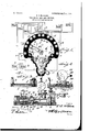
- Figure 1 is a top plan View of my improved combined key and switch, the electric circuits being indicated diagrammatioally.
- Fig. 2 is a sectional view of the same, taken on the plane inment of local wires c, leading from the poles of a local battery w and including in circuit therewith a sounder a and a relay of suitable resistance.
- a conducting-base 4 On the subbase is a conducting-base 4, having an enlarged semicylindrical end 5, provided with number-plates 6 in its upper side,
- a key 7 of the usual or any suitable form is mounted on the conducting-base, as at 8, and has a contact-point 9 to make and break electrical connection with a contactpoint 10, which is insulated from the base 1 and is connected by a wire 11 to the bindingpost 2.
- Binding-posts for a number of lines are arranged in pairs in a semicircle and between the binding-posts 2 3, the pairs of linebinding posts corresponding in number to the number-plates 6 and being respectively designated as 12, 13, 14, 15, and 16.
- One post of each pair is electrically connected to a spring.
- the subbase has an opening 20, with reference to which the contact-arms 16 19 are radially disposed, the same corresponding in position or registering withl the number-plates 6,which indicate the several working circuits.
- a non-conducting pivot-disk 21 ' is mounted to revolve in the said opening 20.
- On the upper side of this pivot-disk isla conducting switch-disk 22, which is secured thereon to revolve therewith and is at all times in electrical contact with a contact-point 23, secured in the subbase and connected electrically -to the binding-post 3.
- Said switch-disk has an arm'2-1, which projects radially therefrom.
- said arm When the disk is appropriately turned, said arm may be caused to pass under anyone of the spring-arms 116 to establish electrical connection therewith and break contact and circuit between said arm 16 and its associate electrode 17.
- a switch-disk 25 On the under side of the pivotdisk and insulated thereby from the switchdisk 22 is a switch-disk 25, which is secured to the pivot-disk to rotate therewith and has an arm 26 to establish electrical contact with any ofthe contact spring-arms 17.
- the key may be put .in circuit with any one of the various working lines, thus enabling thekey to be used in connection with any of said working lines at will, the circuit being from one pole of the local battery to post 2, through the key, through the base 1, post 27,' disk 25, arm 26 thereof, arm 19, one of the working lines, arm 116, disk 22, contact 23, and post 3 to the other pole of the local battery.
- the switch-disk 25 is connected electrically with the conducting-base by a pivot-post 27,
- switch-arm 29 which has its bearing in an opening 28 in the base 4, and tothe upper end of said pivotpost is attached a switch-arm 29.
- This switcharm coacts with the number-plates to put the key in any of the working lines or circuits, as will be understood.
- I provide the arm 24 of the switch-disk 22 with a non-conducting radial extension 30,-comprisinga thin strip of rubber or other suitable non-,conducting material which passes between the said contacts 16 17 and effectually prevents shortcircuiting when the parts become worn and also prevents dust from accumulatingbetween such contacts.
- improved combined key and switch is especially useful in a train-dispatchers oiiice, as in case of wire'trouble on the regular trainwire it becomes necessary to get another wire in order to send his messages.
- a combined telegraph key and switch comprising a non-conducting subbase having an opening, pairs of line-connectors secured .to the subbase, pairs of spring-contacts on the upper and lower sides of the subbase, one of each of said contacts being connected to one of the line-connectors, a conducting-base on the subbase, a key on the base, local batteryconnectors, one connected to the contact of the key, an insulating-plug revoluble in the opening in the subbase, conducting switchdisks on the upper and lower sides of the plug, revoluble therewith, normally in contact with the spring-contacts and having arms to engage the spring-contacts to include the key in circuit with any pair of line-connectors, one of said switch-disks being connected to the other local battery-connector, a conducting pivot-post connected to the other switch-disk and the conducting-base, the plug and both of the switch-disks being revoluble with the pivot-post and the latter having means whereby it may be turned, substantially
- An instrument of the class described having normally closed circuit -closers for a plurality of working circuits, said circuitclosers including contact-springs, a key, and a switch device having means to open any of such circuit-closers and including the key in any of the working circuits at will, said circuit-opening means including a revoluble conducting-arm to engage and operate the contact-spring and having a non-conducting radial extension to pass between said contactsprings and their coacting contacts, for the purposes set forth.
Landscapes
- Engineering & Computer Science (AREA)
- Computer Networks & Wireless Communication (AREA)
- Signal Processing (AREA)
- Push-Button Switches (AREA)
Description
No. 791,163. Y PATBNTBD MAY 3o, 1905.
T. J. MOADAMVS. TELBGRAPH KEY vAND SWITCH.v
4APILIOA'IJIN FILED MAY 19, 1904.
,man
UNITED STATES Patented May 30, 1905.
PATENT OFFICE.
TELEGRAPH KEY AND SWITCH.
SPECIFICATION forming part of Letters Patent No. 791,103, dated May 30, 1905. Application filed May 19, 1904. Serial No. 298,741.
To all whom it may concern:
Be it known that I, THOMAS J, M'cADAMs, a citizen of the United States, 'residing at Annapolis, in the county of'Iron and State of Missouri, have invented certain new and useful Improvements 1n Telegraph Keys and Switches; and I do declare the following to be a full, clear, and exact description of the invention, such as will enable others skilled in the art to which it appertainsto make and usethe same. My invention is an improved combined telegraph key and switch to enable an Yoperator to work any one of a number of wires by means' of the same key and without leaving his seat; and it consists in the construction, combination, and arrangement of devices hereinafter described and claimed.
ln the accompanying drawings, Figure 1 is a top plan View of my improved combined key and switch, the electric circuits being indicated diagrammatioally. Fig. 2 is a sectional view of the same, taken on the plane inment of local wires c, leading from the poles of a local battery w and including in circuit therewith a sounder a and a relay of suitable resistance.
On the subbase is a conducting-base 4, having an enlarged semicylindrical end 5, provided with number-plates 6 in its upper side,
(here shown as live in num ber,) arranged in a curve and numbered consecutively, as shown. Any suitable number of the said plates may be used. A key 7 of the usual or any suitable form is mounted on the conducting-base, as at 8, and has a contact-point 9 to make and break electrical connection with a contactpoint 10, which is insulated from the base 1 and is connected by a wire 11 to the bindingpost 2. Binding-posts for a number of lines are arranged in pairs in a semicircle and between the binding-posts 2 3, the pairs of linebinding posts corresponding in number to the number-plates 6 and being respectively designated as 12, 13, 14, 15, and 16. One post of each pair is electrically connected to a spring.
electrode-arm 116 on the upper side of the subbase, the other post of each pair being connected to'a contact 17, which is normally engaged in closed circuit by the spring-arm 116 and has in a recess 18 in the bottom of the subbase a Contact spring-arm 19.
The subbase has an opening 20, with reference to which the contact-arms 16 19 are radially disposed, the same corresponding in position or registering withl the number-plates 6,which indicate the several working circuits. A non-conducting pivot-disk 21 'is mounted to revolve in the said opening 20. On the upper side of this pivot-disk isla conducting switch-disk 22, which is secured thereon to revolve therewith and is at all times in electrical contact with a contact-point 23, secured in the subbase and connected electrically -to the binding-post 3. Said switch-disk has an arm'2-1, which projects radially therefrom. When the disk is appropriately turned, said arm may be caused to pass under anyone of the spring-arms 116 to establish electrical connection therewith and break contact and circuit between said arm 16 and its associate electrode 17. On the under side of the pivotdisk and insulated thereby from the switchdisk 22 is a switch-disk 25, which is secured to the pivot-disk to rotate therewith and has an arm 26 to establish electrical contact with any ofthe contact spring-arms 17. Hence by turning the pivot-disk the key may be put .in circuit with any one of the various working lines, thus enabling thekey to be used in connection with any of said working lines at will, the circuit being from one pole of the local battery to post 2, through the key, through the base 1, post 27,' disk 25, arm 26 thereof, arm 19, one of the working lines, arm 116, disk 22, contact 23, and post 3 to the other pole of the local battery.
The switch-disk 25 is connected electrically with the conducting-base by a pivot-post 27,
IOO
which has its bearing in an opening 28 in the base 4, and tothe upper end of said pivotpost is attached a switch-arm 29. This switcharm coacts with the number-plates to put the key in any of the working lines or circuits, as will be understood.
Where box-relays are usedon the main-line wires, it is only necessary to keep up the battery in the local oiice for the set of instruments therein included in circuit with such battery. A pin-board is indicated at z in Fig. 1.
To insure breaking of the line-circuits at the contacts 16 17 to cut in the key, I provide the arm 24 of the switch-disk 22 with a non-conducting radial extension 30,-comprisinga thin strip of rubber or other suitable non-,conducting material which passes between the said contacts 16 17 and effectually prevents shortcircuiting when the parts become worn and also prevents dust from accumulatingbetween such contacts.
'Stops 31 on the base 4 limit the angular movement of ,the switch-arm 29. p
improved combined key and switch is especially useful in a train-dispatchers oiiice, as in case of wire'trouble on the regular trainwire it becomes necessary to get another wire in order to send his messages.
From the foregoing description, taken in connection with the accompanying drawings, the construction and operation of the invention will be readily understood without requiring a more extended explanation.
Various changes in the form, proportion, and the minor details of construction may be resorted to Without departing from the principle or sacrificing any of the advantages of this invention.
Having thus fully described my invention, what I claim as new, and desire to secure by Letters Patent, is-
1. A combined telegraph key and switch comprising a non-conducting subbase having an opening, pairs of line-connectors secured .to the subbase, pairs of spring-contacts on the upper and lower sides of the subbase, one of each of said contacts being connected to one of the line-connectors, a conducting-base on the subbase, a key on the base, local batteryconnectors, one connected to the contact of the key, an insulating-plug revoluble in the opening in the subbase, conducting switchdisks on the upper and lower sides of the plug, revoluble therewith, normally in contact with the spring-contacts and having arms to engage the spring-contacts to include the key in circuit with any pair of line-connectors, one of said switch-disks being connected to the other local battery-connector, a conducting pivot-post connected to the other switch-disk and the conducting-base, the plug and both of the switch-disks being revoluble with the pivot-post and the latter having means whereby it may be turned, substantially as described.
2. An instrument of the class described, having normally closed circuit -closers for a plurality of working circuits, said circuitclosers including contact-springs, a key, and a switch device having means to open any of such circuit-closers and including the key in any of the working circuits at will, said circuit-opening means including a revoluble conducting-arm to engage and operate the contact-spring and having a non-conducting radial extension to pass between said contactsprings and their coacting contacts, for the purposes set forth.
In testimony whereofl I have hereunto set my hand in presence of two subscribing witnesses.
THOMAS J. MCADAMS.
Witnesses:
I. J. BURFORD, J. W. HOAGLAND.
Priority Applications (1)
| Application Number | Priority Date | Filing Date | Title |
|---|---|---|---|
| US20874104A US791103A (en) | 1904-05-19 | 1904-05-19 | Telegraph key and switch. |
Applications Claiming Priority (1)
| Application Number | Priority Date | Filing Date | Title |
|---|---|---|---|
| US20874104A US791103A (en) | 1904-05-19 | 1904-05-19 | Telegraph key and switch. |
Publications (1)
| Publication Number | Publication Date |
|---|---|
| US791103A true US791103A (en) | 1905-05-30 |
Family
ID=2859592
Family Applications (1)
| Application Number | Title | Priority Date | Filing Date |
|---|---|---|---|
| US20874104A Expired - Lifetime US791103A (en) | 1904-05-19 | 1904-05-19 | Telegraph key and switch. |
Country Status (1)
| Country | Link |
|---|---|
| US (1) | US791103A (en) |
-
1904
- 1904-05-19 US US20874104A patent/US791103A/en not_active Expired - Lifetime
Similar Documents
| Publication | Publication Date | Title |
|---|---|---|
| US791103A (en) | Telegraph key and switch. | |
| US1289637A (en) | Telegraph apparatus. | |
| US466508A (en) | Gwynne e | |
| US547460A (en) | Andrew b craham | |
| US607251A (en) | Harry a | |
| US717558A (en) | Contact device for time-detectors. | |
| US479859A (en) | Telegraph-key | |
| US506092A (en) | Electrical switch | |
| US763464A (en) | Circuit-closing device. | |
| US824031A (en) | Telegraphic transmitting-key. | |
| US746726A (en) | Electrical signal system. | |
| US497942A (en) | District-telegraph return-si g nal key | |
| US1090201A (en) | Charging-switch for storage batteries. | |
| US785266A (en) | Resonator-switch. | |
| US1239887A (en) | Fire-alarm signal-box. | |
| US474623A (en) | andrews | |
| US339298A (en) | johnson | |
| US756408A (en) | Call or alarm device for hotels or other buildings. | |
| US563025A (en) | Mortimer du perow | |
| US808777A (en) | Telegraph-key. | |
| US449301A (en) | Cut-out | |
| US677453A (en) | Telegraph switching apparatus. | |
| US488993A (en) | John chisholm francis | |
| US492219A (en) | Lightning conductor and arrester | |
| US637794A (en) | Lightning-arrester. |