US79110A - Peters - Google Patents
Peters Download PDFInfo
- Publication number
- US79110A US79110A US79110DA US79110A US 79110 A US79110 A US 79110A US 79110D A US79110D A US 79110DA US 79110 A US79110 A US 79110A
- Authority
- US
- United States
- Prior art keywords
- generator
- sections
- steam
- water
- hub
- Prior art date
- Legal status (The legal status is an assumption and is not a legal conclusion. Google has not performed a legal analysis and makes no representation as to the accuracy of the status listed.)
- Expired - Lifetime
Links
- XLYOFNOQVPJJNP-UHFFFAOYSA-N water Substances O XLYOFNOQVPJJNP-UHFFFAOYSA-N 0.000 description 28
- 238000010276 construction Methods 0.000 description 10
- 239000002184 metal Substances 0.000 description 6
- 229910052751 metal Inorganic materials 0.000 description 6
- 238000002485 combustion reaction Methods 0.000 description 4
- 230000000694 effects Effects 0.000 description 4
- XEEYBQQBJWHFJM-UHFFFAOYSA-N iron Chemical compound [Fe] XEEYBQQBJWHFJM-UHFFFAOYSA-N 0.000 description 4
- 241000283690 Bos taurus Species 0.000 description 2
- 229910001018 Cast iron Inorganic materials 0.000 description 2
- 210000001503 Joints Anatomy 0.000 description 2
- 230000001174 ascending Effects 0.000 description 2
- 230000005540 biological transmission Effects 0.000 description 2
- 230000002939 deleterious Effects 0.000 description 2
- 239000007789 gas Substances 0.000 description 2
- 239000011796 hollow space material Substances 0.000 description 2
- 230000000266 injurious Effects 0.000 description 2
- 229910052742 iron Inorganic materials 0.000 description 2
- 238000004519 manufacturing process Methods 0.000 description 2
- 230000000630 rising Effects 0.000 description 2
Images
Classifications
-
- F—MECHANICAL ENGINEERING; LIGHTING; HEATING; WEAPONS; BLASTING
- F24—HEATING; RANGES; VENTILATING
- F24H—FLUID HEATERS, e.g. WATER OR AIR HEATERS, HAVING HEAT-GENERATING MEANS, e.g. HEAT PUMPS, IN GENERAL
- F24H1/00—Water heaters, e.g. boilers, continuous-flow heaters or water-storage heaters
- F24H1/22—Water heaters other than continuous-flow or water-storage heaters, e.g. water heaters for central heating
- F24H1/38—Water heaters other than continuous-flow or water-storage heaters, e.g. water heaters for central heating with water contained in separate elements, e.g. radiator-type element
Definitions
- Figure'Z is pla-n view of the saine.4 1
- Figure 3 is another pltm view ofthe sonic, ⁇ showing a. modified construction.
- Figure 4 is vertical-section through the entire generutor.
- i Figure 5 is n horizontalsection through the arnis and rim of 'one division. ⁇
- My invention relates tot. steam-generator constructed oi' enst metal, in sections ordivisio'ns, which may bel 4 unitedibybolts Vor otherwise; and it consists- First, in the form'. and arrangement of the said/sections. Second, in ⁇ the manner 'of introducing. feedfwater. Third,'in lthe manner of preventing injurious deposits of scale', die., ,within the generator. Fourth, in the nnnnner of securing the ⁇ various sections together.
- the water-space within the rim and spokes of eheh section ⁇ may he cylindrical if preferred, but, in my opinion, itV is better to construct it with a continuous enlargement from points between'- the spokes., through said spokes, to the central spece or hub, for the reason that suclr construction will afford perfect drainage' into the central cylinder, so. that lneither water nor steam will he trapped ⁇ and stand in the hollows of either ,rimer ⁇ spokes.
- This vmode. of construction is clearly shown in figs. 4 and 5, while iig. 3 exhi'hitss7 section having cylindricnl arms-and rim.
- the feed-water pipe, B is introduced through the side of the central cylinder or huh', and extends nearly or quite to-the centre thereof, as shown in iig. 4 so that the'cold feed-water, instead oi'beng discharged against the surfacefofthe generator, is-discharged in the cen'trc of the mass of hot water.
- VThe eifect of 'this is-to relieve the iron from the effect ofunequol expansion, end to increase Vthe circuletiomof the water within theY boiler, and, therefore, increase therupiditywith which steam is evolved.
- the cylinder C is also introducedfor the purpose of aiding to accomplish both of these purposes,.aud byv receiving within itseli ⁇ the columnl of cold water, the same is not-permitted to come in contect with the sh'ell of the generator until the bottom of the cylinderC is reached, by whichtime the feed-water will have become heatedr
- The-cylinderC A is supported upon legs D D, and if the ,cold feed-water were not received within it, it would 'develope aicomplete circulation of the water containedin the boiler, in accordance withthe wellknown laws.
- the whole may be-'boundy together .hy ebelt, H, passing through thecentre of the hubs of the various sections, a'ndse'cured by screwlnuts, as shown in g. 4.
- the steam-pipe L leads off from the -uppermost section, as shown. Itis provided with the necessary valves and connections. i
- the safety-valve M At the -upper end of the central hub or cylinder is the safety-valve M, whose seat occupies-the entire area of the central cylinder, and, therefore, when raised, itaii'ords the greatest possible space for steam-lescape.
- the safety-valve mayibe secured by a weighted lever in the ordinary manner, as shownin iig. l. i
- a steam-generator constructed of cast iron vor other cast metal, with a hollow cylindrical hub, radiating hollow arms, and 'a hollow rim connecting the out'e'rends of said arms, substantially as set forth.
- a reservoir, E standingv under-the main cylinder of said generator and beneath the iire-grate, asdescribed.
- a steam-generator composed of sections Lin the form vof hollow rings, with hollow radiating arms connecting said rings witha central cylinder or hub, said sections, being placed one above another, and so arranged asy ,tol fill the space within the chimney without being' embedded in the same, and with the radial arms so 'disposed as break joint with each other, allv as set forth and described.
- tubular rods JJ arranged to secure the sections A tc each other, ⁇ and located outside of said sections, so aslto increase the circulation and steam-surface, as described.
Description
en'onenie. Trinite; on New YORKQN; Y.
'Lemie Param: Nb. 79,11o,'zacz--Jum 23, 186s.
IMPROVEMENT 1N 4srsAM-Gemeentes.
To ALL-WHOM 1T MAX' CQNCERN: Y
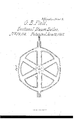
Bie it known thatI, GEQnGE B. FILD, of New Yck, inv the county of Nev#r York, and State of New York, have invented a. new A'and useful Improvement in Steam-Generators; I:indd: do hereby declare the 'following tothe n full, clear, and exactrdeseription o f thesamc, reference 'being had to the accompanying drawings, in which -Figure 1 is a perspective'view of my steam-generator in position, the bric'knork surrounding it beingV broken away. i
Figure'Z is pla-n view of the saine.4 1 i Figure 3 is another pltm view ofthe sonic,` showing a. modified construction. Figure 4 is vertical-section through the entire generutor. i Figure 5 is n horizontalsection through the arnis and rim of 'one division.`
My invention relates tot. steam-generator constructed oi' enst metal, in sections ordivisio'ns, which may bel 4 unitedibybolts Vor otherwise; and it consists- First, in the form'. and arrangement of the said/sections. Second, in `the manner 'of introducing. feedfwater. Third,'in lthe manner of preventing injurious deposits of scale', die., ,within the generator. Fourth, in the nnnnner of securing the `various sections together.
That others may'understand the construction and operation of `my invention, LWiILparticularly ldescribe it. The sections A1A, ,which compose, when joined together, my steam-generator, may belikened to a'wheel with hollow hub, spokes, and rim. These sections `are clearly shown in figs. 1,l 2, and 3 of the drawings,n nd
their internal form mayhejsecn inl figs. 4 and'.. The hollow space is continuous v.through the rind, and is connected'with the h'ollow hub througheach spoke. My bcileror generator is composed of any desirable num? h er of these sections, set one upon another, and secured.A together by bolts or other suitable means.` Each hub `is turned ina. lathe ,with a rabhet and flange, so that they will fit each other accurately, andfwheu the generator is setup, this-joint may be liited if desired. The water-space within the rim and spokes of eheh section` may he cylindrical if preferred, but, in my opinion, itV is better to construct it with a continuous enlargement from points between'- the spokes., through said spokes, to the central spece or hub, for the reason that suclr construction will afford perfect drainage' into the central cylinder, so. that lneither water nor steam will he trapped` and stand in the hollows of either ,rimer` spokes. This vmode. of construction is clearly shown in figs. 4 and 5, while iig. 3 exhi'hitss7 section having cylindricnl arms-and rim.
The feed-water pipe, B, is introduced through the side of the central cylinder or huh', and extends nearly or quite to-the centre thereof, as shown in iig. 4 so that the'cold feed-water, instead oi'beng discharged against the surfacefofthe generator, is-discharged in the cen'trc of the mass of hot water. VThe eifect of 'this is-to relieve the iron from the effect ofunequol expansion, end to increase Vthe circuletiomof the water within theY boiler, and, therefore, increase therupiditywith which steam is evolved.
The cylinder C is also introducedfor the purpose of aiding to accomplish both of these purposes,.aud byv receiving within itseli` the columnl of cold water, the same is not-permitted to come in contect with the sh'ell of the generator until the bottom of the cylinderC is reached, by whichtime the feed-water will have become heatedr The-cylinderC Ais supported upon legs D D, and if the ,cold feed-water were not received within it, it would 'develope aicomplete circulation of the water containedin the boiler, in accordance withthe wellknown laws.
yvhich' 4gorern the motions Iof fluids-the hotter water ascending along the surface of the generator, andthe cooler descending through the centre. V
At some'point a little below'the lowermost section of my generator, is placedV the grate E, and below the grate is a reservoir, F, which isconnected" with the central cylinder or'hub of .the generator' bythe tuhe Gr, and
ifpreferred, the whole may be-'boundy together .hy ebelt, H, passing through thecentre of the hubs of the various sections, a'ndse'cured by screwlnuts, as shown in g. 4.
From the reservoirFlu. Wostefpipe, Lextends outward throughrthebrick or other casing, and is provided with 'a suitable gate or cock, so that said pipe may be opened at will and the contents of the reservoir and boiler drawn oif. The sedimentary matter left when the water within the boiler is being evaporated will not lodge `within the spaces ofthe rims or arms, because of their inclined surfaces and vcomplete drainage, but will grada-- ally find its wayinto the central hub, and from thence will sinlz directly to the reservoir beneath the grate, from whence it can never rise again.
In an ordinary'boiler this sediment settles at the lower point, and when impure water is used, it accumulates soZrapidly that the transmission of heat is in a short time almost entirely arrested, but with my reservoir, where the presence of sediment can exert no deleterious influence, the action of the boiler will be uniform whatever may be the character of the water., i It is evident that thisreservoir below the'grate surface will be equally applicable and useful iirother kinds and styles-of steam-generators. I
It may-be deemed desirable and `advantageous to couple the various sections by wrought tubular rods, J .T1 the ends of whiehare screwed into hollow lugs projecting from the upper and lower-sections, and the Vcentres joined by couplers, KK, 4which are provided with right and left-hand screws, so that by turning said coupler the end sections may be drawn toward eachother.
The steam-pipe L leads off from the -uppermost section, as shown. Itis provided with the necessary valves and connections. i
At the -upper end of the central hub or cylinder is the safety-valve M, whose seat occupies-the entire area of the central cylinder, and, therefore, when raised, itaii'ords the greatest possible space for steam-lescape. The safety-valvemayibe secured by a weighted lever in the ordinary manner, as shownin iig. l. i
When the hot waterfascends along the inside of the st eanrgenerator, it meets an enlargement, N, with a curved .annular channel, the over-arching top of which deflccts the rising current oi'lwateriinward and toward l the descending column at the centre of the boiler.
From the form shown, it will appear 'that my steam-generator may beset in the fine of the stack, instead i 'of .being placed at one side'of the same, and protected by a. separate structure.
' The products of combustion' and burning gases arising from the grate E pass upwards among the arms of. sections, constantly intercepted andimpeded by them, so that a large share ot'lthe heat is extracted before it is passed 'above the generator. The more completely to arrest and impede the upward current of heated air and dame, the arms ofthe sections are arranged so .as tobreak space with each other, as shown in' figs, 1, 2, andY The sections should, of course, nearly or quite fill the areaof the iiue, so as !o permit as little as possible of the products of combustion to pass upward without contactwith the surface of the generator somewhere. [f it is desired to employ a square flue, then the sections should correspond to that form, as shown in tig.
AAmong the advantages of this system lmay be enumerated cheapness of construction, ease of manufacture and fitting, few joints to keep tight, and general compactness, with a'great expanse of heating-surfaee, facility ofv removing sedimentary matters, Btc., 85o. i I
Having described my invention,wl1at claim as new, isV
1. A steam-generator, constructed of cast iron vor other cast metal, with a hollow cylindrical hub, radiating hollow arms, and 'a hollow rim connecting the out'e'rends of said arms, substantially as set forth.
2. Constructing a cast-metal steam-generator, as above described, with a continuous enlargement of the Water-*space from a pointbetween the arms,ithrough the sameyto thc central hub, 'as described and shown 3. The cylinder C, arranged as shown and described, and for the purpose set Aforth. v
4. In combination', with vthe sections A, of a steam-generator, such as described, a reservoir, E, standingv under-the main cylinder of said generator and beneath the iire-grate, asdescribed.
5. -In connection with the central cylinder or hub of a stcaimgeneratm, such as described, and the enclosed cylinder C, the annular enlargement N, for' thc-purpose and with the effect set-forth.
6*..In combination with a steam-generator, composed of one or .more sections, as hereinvdescribech the safety-valve M, having anorice as large as the interior diameteriot` the'cylindriea hub or largest tube of the' generator, as set forth and described.
Pi..The'arrangement of the feedpipe B, in connection with the central cylinder-or hub ot' the steam- `generator described, so that the feed-water shall be .discharged at the centre o f the descending current, as set forth and described. l
8` A steam-generator, composed of sections Lin the form vof hollow rings, with hollow radiating arms connecting said rings witha central cylinder or hub, said sections, being placed one above another, and so arranged asy ,tol fill the space within the chimney without being' embedded in the same, and with the radial arms so 'disposed as break joint with each other, allv as set forth and described. Y
9. The tubular rods JJ, arranged to secure the sections A tc each other,` and located outside of said sections, so aslto increase the circulation and steam-surface, as described.
i GEO. B. FIELD.
Witnesses:
R'. D. O. SMITH, EDM. F.- BnowN.
Publications (1)
| Publication Number | Publication Date |
|---|---|
| US79110A true US79110A (en) | 1868-06-23 |
Family
ID=2148609
Family Applications (1)
| Application Number | Title | Priority Date | Filing Date |
|---|---|---|---|
| US79110D Expired - Lifetime US79110A (en) | Peters |
Country Status (1)
| Country | Link |
|---|---|
| US (1) | US79110A (en) |
-
0
- US US79110D patent/US79110A/en not_active Expired - Lifetime
Similar Documents
| Publication | Publication Date | Title |
|---|---|---|
| US79110A (en) | Peters | |
| US97865A (en) | Improvement in steam-generators | |
| US286780A (en) | Geoege clark | |
| US17208A (en) | Improvement in heating feed-water apparatus of locomotives | |
| US52982A (en) | Improvement in steam-superheaters | |
| US421194A (en) | Boiler | |
| US839867A (en) | Feed-water heater. | |
| US83528A (en) | Improvement in steam-generators | |
| US323957A (en) | Feed-water heater | |
| US551949A (en) | Henry s | |
| US352628A (en) | William e | |
| US262392A (en) | Steam-generator | |
| US47232A (en) | Improved sediment-extractor for steam-boilers | |
| US364958A (en) | Sectional boiler | |
| US682398A (en) | Feed-water purifier. | |
| US359672A (en) | Boiler | |
| US920057A (en) | Boiler. | |
| US80396A (en) | davis | |
| US530155A (en) | Heating-boiler | |
| US233624A (en) | Steam-generator | |
| US67621A (en) | Improvement in steam-generatoks | |
| US616531A (en) | Vertical water-tube boiler | |
| US58685A (en) | Improvement in steam-generators | |
| US107356A (en) | Improvement in tubular grates | |
| US526316A (en) | Hot-air heater |