US7907512B1 - OFDM and SC-OFDM QLM - Google Patents
OFDM and SC-OFDM QLM Download PDFInfo
- Publication number
- US7907512B1 US7907512B1 US12/587,687 US58768709A US7907512B1 US 7907512 B1 US7907512 B1 US 7907512B1 US 58768709 A US58768709 A US 58768709A US 7907512 B1 US7907512 B1 US 7907512B1
- Authority
- US
- United States
- Prior art keywords
- data
- qlm
- communications
- subband
- ofdm
- Prior art date
- Legal status (The legal status is an assumption and is not a legal conclusion. Google has not performed a legal analysis and makes no representation as to the accuracy of the status listed.)
- Active
Links
- 238000004891 communication Methods 0.000 claims abstract description 108
- 238000004422 calculation algorithm Methods 0.000 claims abstract description 55
- 238000007476 Maximum Likelihood Methods 0.000 claims abstract description 43
- 238000012545 processing Methods 0.000 claims abstract description 28
- 238000000034 method Methods 0.000 claims abstract description 15
- 239000010410 layer Substances 0.000 claims description 94
- 239000013598 vector Substances 0.000 claims description 59
- 230000002596 correlated effect Effects 0.000 claims description 24
- 230000005540 biological transmission Effects 0.000 claims description 20
- 239000011159 matrix material Substances 0.000 claims description 14
- 230000000875 corresponding effect Effects 0.000 claims description 12
- 238000001514 detection method Methods 0.000 claims description 11
- 238000012937 correction Methods 0.000 claims description 7
- 238000013461 design Methods 0.000 claims description 7
- 238000005192 partition Methods 0.000 claims description 4
- 230000001360 synchronised effect Effects 0.000 claims description 4
- 239000002356 single layer Substances 0.000 claims description 3
- 230000003595 spectral effect Effects 0.000 claims description 3
- 230000007774 longterm Effects 0.000 claims description 2
- 238000004088 simulation Methods 0.000 abstract description 2
- 238000005516 engineering process Methods 0.000 description 6
- 238000010586 diagram Methods 0.000 description 5
- 230000004044 response Effects 0.000 description 5
- 230000007480 spreading Effects 0.000 description 5
- 238000000926 separation method Methods 0.000 description 4
- 238000000638 solvent extraction Methods 0.000 description 4
- 238000001228 spectrum Methods 0.000 description 4
- 238000004364 calculation method Methods 0.000 description 3
- 230000010267 cellular communication Effects 0.000 description 3
- 230000006870 function Effects 0.000 description 3
- 230000014509 gene expression Effects 0.000 description 3
- 238000011084 recovery Methods 0.000 description 3
- 239000000654 additive Substances 0.000 description 2
- 230000000996 additive effect Effects 0.000 description 2
- 238000010276 construction Methods 0.000 description 2
- 238000009795 derivation Methods 0.000 description 2
- 238000005259 measurement Methods 0.000 description 2
- 230000003287 optical effect Effects 0.000 description 2
- 230000010363 phase shift Effects 0.000 description 2
- 238000000342 Monte Carlo simulation Methods 0.000 description 1
- 230000001413 cellular effect Effects 0.000 description 1
- 125000004122 cyclic group Chemical group 0.000 description 1
- 230000007274 generation of a signal involved in cell-cell signaling Effects 0.000 description 1
- 238000003384 imaging method Methods 0.000 description 1
- 238000013507 mapping Methods 0.000 description 1
- 238000012986 modification Methods 0.000 description 1
- 230000004048 modification Effects 0.000 description 1
- 230000008450 motivation Effects 0.000 description 1
- 238000010606 normalization Methods 0.000 description 1
- 238000005457 optimization Methods 0.000 description 1
- 238000005070 sampling Methods 0.000 description 1
Images

Classifications
-
- H—ELECTRICITY
- H04—ELECTRIC COMMUNICATION TECHNIQUE
- H04L—TRANSMISSION OF DIGITAL INFORMATION, e.g. TELEGRAPHIC COMMUNICATION
- H04L5/00—Arrangements affording multiple use of the transmission path
- H04L5/0001—Arrangements for dividing the transmission path
- H04L5/0014—Three-dimensional division
-
- H—ELECTRICITY
- H04—ELECTRIC COMMUNICATION TECHNIQUE
- H04J—MULTIPLEX COMMUNICATION
- H04J13/00—Code division multiplex systems
- H04J13/0007—Code type
- H04J13/004—Orthogonal
- H04J13/0048—Walsh
-
- H—ELECTRICITY
- H04—ELECTRIC COMMUNICATION TECHNIQUE
- H04J—MULTIPLEX COMMUNICATION
- H04J13/00—Code division multiplex systems
- H04J13/10—Code generation
- H04J13/12—Generation of orthogonal codes
-
- H—ELECTRICITY
- H04—ELECTRIC COMMUNICATION TECHNIQUE
- H04L—TRANSMISSION OF DIGITAL INFORMATION, e.g. TELEGRAPHIC COMMUNICATION
- H04L1/00—Arrangements for detecting or preventing errors in the information received
- H04L1/004—Arrangements for detecting or preventing errors in the information received by using forward error control
- H04L1/0045—Arrangements at the receiver end
-
- H—ELECTRICITY
- H04—ELECTRIC COMMUNICATION TECHNIQUE
- H04L—TRANSMISSION OF DIGITAL INFORMATION, e.g. TELEGRAPHIC COMMUNICATION
- H04L25/00—Baseband systems
- H04L25/02—Details ; arrangements for supplying electrical power along data transmission lines
- H04L25/03—Shaping networks in transmitter or receiver, e.g. adaptive shaping networks
- H04L25/03006—Arrangements for removing intersymbol interference
- H04L25/03178—Arrangements involving sequence estimation techniques
- H04L25/03203—Trellis search techniques
-
- H—ELECTRICITY
- H04—ELECTRIC COMMUNICATION TECHNIQUE
- H04L—TRANSMISSION OF DIGITAL INFORMATION, e.g. TELEGRAPHIC COMMUNICATION
- H04L27/00—Modulated-carrier systems
- H04L27/26—Systems using multi-frequency codes
- H04L27/2601—Multicarrier modulation systems
- H04L27/2626—Arrangements specific to the transmitter only
- H04L27/2627—Modulators
-
- H—ELECTRICITY
- H04—ELECTRIC COMMUNICATION TECHNIQUE
- H04L—TRANSMISSION OF DIGITAL INFORMATION, e.g. TELEGRAPHIC COMMUNICATION
- H04L27/00—Modulated-carrier systems
- H04L27/26—Systems using multi-frequency codes
- H04L27/2601—Multicarrier modulation systems
- H04L27/2647—Arrangements specific to the receiver only
- H04L27/2649—Demodulators
- H04L27/26524—Fast Fourier transform [FFT] or discrete Fourier transform [DFT] demodulators in combination with other circuits for demodulation
- H04L27/26526—Fast Fourier transform [FFT] or discrete Fourier transform [DFT] demodulators in combination with other circuits for demodulation with inverse FFT [IFFT] or inverse DFT [IDFT] demodulators, e.g. standard single-carrier frequency-division multiple access [SC-FDMA] receiver or DFT spread orthogonal frequency division multiplexing [DFT-SOFDM]
-
- H—ELECTRICITY
- H04—ELECTRIC COMMUNICATION TECHNIQUE
- H04L—TRANSMISSION OF DIGITAL INFORMATION, e.g. TELEGRAPHIC COMMUNICATION
- H04L5/00—Arrangements affording multiple use of the transmission path
- H04L5/02—Channels characterised by the type of signal
- H04L5/04—Channels characterised by the type of signal the signals being represented by different amplitudes or polarities, e.g. quadriplex
Definitions
- the present invention relates to cellular communications and also relates to the Nyquist rate for data symbol transmission, the Shannon bound on communications capacity, and symbol modulation and demodulation for high-data-rate satellite, airborne, wired, wireless, and optical communications and includes all of the communications symbol modulations and the future modulations for single links and multiple access links which include electrical and optical wired, mobile, point-to-point, point-to-multipoint, multipoint-to-multipoint, cellular, multiple-input multiple-output MIMO, and satellite communication networks.
- WiFi, WiMax and long-term evolution LTE for cellular communications and satellite communications.
- WiFi, WiMax use orthogonal frequency division multiplexing OFDM on both links and LTE uses SC-OFDM on the uplink from user to base station and OFDM on the downlink form base station to user.
- WiMax occupies a larger frequency band than WiFi and both use OFDM waveforms.
- SC-OFDM is a single carrier orthogonal waveform version of OFDM which uses orthogonal frequency subbands of varying widths.
- the Nyquist rate is the complex digital sampling rate equal to B that is sufficient to include all of the information within a frequency band B.
- equivalent expressions for the Nyquist rate bound are defined in equations (1). T s ⁇ 1 /B (1) BT S ⁇ 1 wherein 1/T s is the data symbol transmission rate in the frequency band B which means T s is the spacing between the data symbols.
- the Shannon bound for the maximum data rate C is a bound on the corresponding number of information bits per symbol b as well as a bound on the communications efficiency ⁇ and is complemented by the Shannon coding theorem, and are defined in equations (2).
- the maximum data rate supported by WiFi standard is calculated in 3 to be ⁇ 57 Mbps using 256QAM modulation and wherein “ ⁇ ” represents an approximate value.
- OFDM uses pulse waveforms in time and relies on the OFDM tone modulation to provide orthogonality.
- SC-OFDM is a pulse-shaped OFDM that uses shaped waveforms in time to roll-off the spectrum of the waveform between adjacent channels to provide orthogonality, allows the user to occupy subbands of differing widths, and uses a different tone spacing, data packet length, and sub-frame length compared to OFDM for WiFi, WiMax.
- This invention introduces a maximum likelihood ML demodulation architecture and implementation of a quadrature layered modulation QLM for OFDM and SC-OFDM modulations to provide a method for increasing the data rates.
- QLM for OFDM WiFi provides a method for increasing the data rates to 4.75 ⁇ WiFi maximum data rate with current technology (4.75 times the WiFi maximum rate) and to 6 ⁇ WiFi maximum data rate with technology advances.
- QLM provides similar increases in data rate for OFDM WiMax and SC-OFDM LTE.
- QLM supports data symbol rates that can be multiples of the Nyquist rate and communications data rates that can be multiples of the Shannon bound.
- a representative OFDM QLM architecture using ML demodulation is disclosed in this invention for WiFi standard and the transmit and receive signal processing algorithms and supporting block diagrams are developed to illustrate the architecture and implementation.
- This architecture is directly applicable to WiMax by increasing the number of OFDM tones to occupy the increased WiMax frequency band and also is directly applicable to SC-OFDM since the OFDM QLM ML architecture uses a pulse-shaped OFDM which partitions the frequency band into orthogonal subbands that can be combined to enable users to use differing frequency bands to implement SC-OFDM.
- the QLM is a layered topology for transmitting higher data rates than possible with a single layer of communications and is implemented by transmitting each layer with a differentiating parameter which enables separation and decoding of each layer.
- the OFDM WiFi QLM transmits the QLM signals over a set of subbands which together occupy the same frequency band as the WiFi standard 48 data symbol modulated FFT ⁇ 1 tones and over the WiFi 4 ⁇ s data packet.
- Computationally efficient fast multi-channel FFT ⁇ 1 and FFT algorithms generate the subband QLM data symbols for transmission and implement the receive detection followed by maximum likelihood ML demodulation, which can be implemented with a chip architecture that supports both OFDM WiFi and the OFDM WiFi QLM in this invention disclosure as well as both OFDM WiMax and OFDM WiMax QLM with an increase in the frequency band, and with parameter changes the chip architecture supports both SC-OFDM LTE and SC-OFDM LTE QLM uplinks and both OFDMA LTE and OFDMA LTE QLM downlinks.
- Monte Carlo Matlab direct error count bit-error-rate BER simulations for ML demodulation used in OFDM WiFi QLM demonstrate the QLM performance.
- a multi-scale MS code can be implemented with modest complexity in order to improve the bit-error-rate BER performance of OFDM WiFi QLM by spreading each transmitted data symbol over the OFDM WiFi QLM data band and over the 4 ⁇ s data packet. Jensen's inequality from mathematical statistics proves that this uniform spreading of the Tx signals using MS provides the best communications BER performance.
- FIG. 1 describes the OFDM waveform for the WIFi standard.
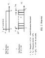
- FIG. 2 describes how to increase the data rate using a pulse waveform.
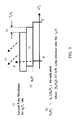
- FIG. 3 describes how QLM increases the data rate for a pulse waveform at a constant frequency bandwidth.
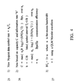
- FIG. 4 presents the equations for the communications capacity predicted by the new bound, the new Nyquist data symbol rate, and the BT S product for a Wavelet waveform.
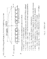
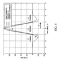
- FIG. 5 calculates the ideal pulse correlation, candidate waveform ⁇ time response, and the ⁇ correlation.
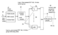
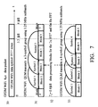
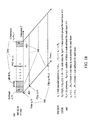
- FIG. 7 describes the OFDM WiFi QLM 3-data symbol group and 4-data symbol group in each of the subbands and over the 4 ⁇ s WiFi data packet.
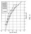
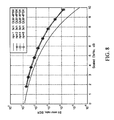
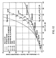
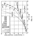
- FIG. 10 for the OFDM architecture calculates the information bits b per symbol interval equivalently expressed as Bps/Hz versus E b /N o for the new bound, Shannon bound, for PSK, QAM with turbo coding to bring the performance to essentially equal to the Shannon bound, and for QLM 3,4-data symbol group performance using 64QAM.
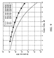
- FIG. 11 for the OFDM architecture calculates the information bits b per symbol interval expressed as Bps/Hz versus E b /N o for the new bound, Shannon bound, for PSK, QAM with turbo coding to bring the performance to essentially equal to the Shannon bound, and for QLM 3,4-data symbol group performance using 256QAM.
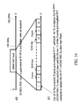
- FIG. 14 describes the partitioning of the OFDM WiFi standard 20 MHz band into 16 OFDM WiFi QLM subbands.
- FIG. 15 presents the implementation steps in the transmitter to generate the OFDM WiFi QLM baseband signal vector starting with the input data symbols for the 4 ⁇ s data packet
- FIG. 16 presents the implementation steps in the receiver to recover the estimated OFDM WiFi QLM input data symbols starting with the received OFDM WiFi QLM baseband signal vector for the 4 ⁇ s data packet.
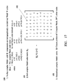
- FIG. 17 defines the complex Walsh codes and the generalized complex Walsh codes.
- FIG. 18 describes the multi-scale MS encoding of each layer of OFDM WiFi QLM which spreads each data symbol vector within the subbands and over the subbands.
- FIG. 19 is a representative transmitter implementation block diagram for the OFDM WiFi QLM mode.
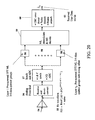
- FIG. 20 is a representative receiver implementation block diagram for the OFDM WiFi QLM mode.
- OFDM and SC-OFDM applications of quadrature layered modulation QLM in this invention disclosure are illustrated by the WiFi 802.16 standard which uses OFDM on both uplinks and downlinks between the user and base station for cellular communications as well as for communications with satellites.
- OFDM WiFi QLM replaces the OFDM orthogonal data symbol tones with orthogonal subbands which are the same architecture as SC-OFDM used for the LTE uplink.
- the OFDM WiFi QLM architecture is directly applicable to WiMax by simply increasing the number of subbands since they both use the same OFDM and 4 ⁇ s data packets with WiMax using a larger frequency band, and also is directly applicable to the LTE uplink since the OFDM WiFi QLM orthogonal subbands partition the frequency spectrum using the same architecture as SC-OFDM for LTE to allow the various users to be assigned differing orthogonal frequency subbands across the frequency band and the QLM data symbol waveforms in these subbands are SC-OFDM subband shaped waveforms used for LTE.
- the OFDM WiFi QLM architecture is directly applicable to LTE downlinks which use OFDM.
- OFDM WiFi QLM uses maximum likelihood ML demodulation of the quadrature layered modulation QLM received correlated data symbols to support an architecture and implementation for QLM communications using the WiFi 4 ⁇ s data packet over the 20 MHz WiFi band for the WiFi standard and with obvious extensions to the other WiFi versions.
- FIG. 2 introduces QLM by considering an ideal pulse waveform in the time domain.
- [“o”] is the value of “o” for the communications channel when there is no layering.
- FIG. 3 describes the layering of the communications channels for QLM and equation (3) defines the QLM scaling of the E b /N o and S/N.
- QLM is a layered topology for transmitting higher data rates than possible with each layer of communications and is implemented by transmitting each layer with a differentiating parameter which enables separation and decoding of each layer.
- Each layer or channel has a unique differentiating parameter such as time offset as in FIG. 3 and/or frequency offset.
- Each layer or channel obeys Shannon's laws when using QLM scaling in equations (3).
- the new coding theorem in 4 in equations (5) states that C is the upper bound on the information data rate R b in bits/second for which error correcting codes exist to provide reliable communications with an arbitrarily low bit error rate BER wherein C is defined in 1 in equations (5) and upgrades the Shannon coding theorem 3 in equations (1) using new capacity bound C in 1 in equations (5) and introduces the new data symbol rate 5 whose maximum value max ⁇ n p /T s ⁇ is n p times the Nyquist rate for a single channel.
- QLM demodulation received signal processing synchronizes and removes the received waveform by performing a convolution of the received waveform encoded data symbol with the complex conjugate of this waveform, to detect the correlated data symbols.
- This convolution is a correlation of the waveform with itself as illustrated in FIG. 5 since the waveforms are real and symmetric.
- These correlated data signals are processed with a trellis algorithm to recover estimates of the encoded symbol data, or processed by a ML algorithm to recover estimates of the data symbols, or processed by a recursive relaxation algorithm or another demodulation algorithm to recover the transmitted data symbols.
- FIG. 5 calculates the ideal triangular correlation 10, an example waveform 11 designated by ⁇ , and the waveform ⁇ correlation 12.
- the ideal triangular correlation is the correlation for the pulse waveform of length T s in FIG. 3 and FIG. 5 demonstrates that for waveforms of interest for QLM the triangular correlation approximates the mainlobe correlations for QLM waveforms.
- FIG. 7 is a representative OFDM WiFi QLM architecture and implementation used to illustrate the implementation and performance.
- the OFDM WiFi QLM architecture partitions the WIFi 20 MHz frequency band into 16 1.25 MHz subbands and uses the WiFi 4 ⁇ S data packet 30 to transmit the maximum likelihood ML 3,4-data symbol groups in each OFDM WiFi QLM data subband by partitioning the data packet into data processing blocks for implementation of the OFDM WiFi QLM for transmission Tx using a post-weighted inverse fast fourier transform N-point FFT ⁇ 1 algorithm and for the receiver Rx using a pre-weighted fast fourier transform N-point FFT algorithm followed by a ML demodulation algorithm.
- Mainlobes of the representtive waveforms in FIG. 5 for the 3,4-data symbol groups are depicted in 31 and 33 and each extends over a 2Ts length as depicted in 13 in FIG. 5
- the data symbols for the additional layers are overlayed as shown in FIG. 2 on data symbols 1 , 2 and 1 , 2 , 3 and extend over data symbol 3 and 4 respectively.
- N s (n s ⁇ 1)n p +1 wherein n s is the number of contiguous data symbols in the ground layer group, N s is the number of data symbols in the n s -data symbol group for n p layers, and the index s identifies the data symbols in the order they are processed in the transmitter and in the receiver.
- FIG. 7 OFDM WiFi QLM architecture for the n s -data symbol groups allows the ML system equations to be written in equation (6) for each set of N s detected correlated data symbols over the OFDM WiFi QLM 4 ⁇ s data packet in each of the subbands k and enables a ML demodulation algorithm to be implemented to recover the estimates of the data symbols.
- BER measurements also apply to Wavelet and other waveforms since their correlations closely approximate ideal correlations in FIG. 5 .
- Measured BER performance losses compared to ideal 4 PSK are expected to be the same for all data symbol modulations including 8 PSK, 16QAM, 64QAM, 256QAM, 2048QAM since the ML demodulation estimates the data symbols in each layer independent of the data symbol modulation.
- the 4 PSK modulation was used as a convenient modulation to measure the ML demodulation loss which loss is expected to apply to all data symbol modulations.
- the 4 PSK, 8 PSK are 4-phase, 8-phase phase shift keying modulations which respectively encode 2,3 bits per symbol and 16QAM, 64QAM, 256QAM, 1024QAM are 16, 64, 256, 4096 state QAM modulations which respectively encode 4, 6, 8, 12 bits.
- turbo coding performance provides a performance almost equal to the Shannon bound.
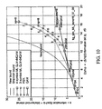
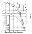
- OFDM WiFi QLM performance calculations in FIGS. 10-13 use the information rates 1 , scaling laws 2 , and demodulation losses 3 in equations ( 8 ).
- OFDM WiFi QLM examples in equations (9) illustrate the performance calculated in FIGS. 10-13 using equations (8).
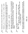
- the OFDM WiFi QLM maximum information rate b in equations (9) is listed in 1 in equations (10) and the corresponding Tx maximum data rate R b vs the WiFi 256QAM maximum data rate is calculated in 2 in equations (10).
- FIG. 14 starts implementation of the OFDM WiFi QLM representative architecture with the generation of the subband filters by a computationlly efficient N-point pre-weighted FFT ⁇ 1 algorithm.
- the 20 MHz WiFi band 40 is partitioned into a 16 subband filters 41 which are labeled form 1 to 16.
- the N can be equal to 16 or could be considerably larger if is necessary to generate more than 16 digital samples per symbol length in order to generate a number >16 which has a divisor equal to the n p of interest so that the timing for each layer falls on a digital sample.
- Subbands 2 and 15 each transmit the WiFi 2-tones at the edges of the data tone band.
- OFDM WiFi QLM architecture definitions include the following:
- ⁇ 7 ⁇ offset ⁇ ⁇ to ⁇ ⁇ specify ⁇ ⁇ the ⁇ ⁇ ⁇ ⁇ ⁇ waveform ⁇ ⁇ indexed ⁇ ⁇ by ⁇ ⁇ i 0 ⁇ for ⁇ ⁇ processing ⁇ ⁇ over ⁇ ⁇ a ⁇ ⁇ data ⁇ ⁇ block ( 11 )
- FIG. 15 constructs the Tx baseband signal z(i) row vector [1 ⁇ 5N] z wherein the number of indices of clocks in the 4 ⁇ data packet is equal to N in each of the 5 blocks, using the implementation of the computationally efficient post-weighted FFT ⁇ 1 algorithm to generate the subband QLM data symbols z(i 0
- Four implementation steps are used to generate the Tx [1 ⁇ 5N] z baseband signal vector z(i).
- Step 1 in 11 starts the implementation by calculating FFT ⁇ 1 ⁇ x(s
- k) ⁇ [1 ⁇ N] x row vector indexed on i 0 in equations (13) for each s.
- Step 2 in 12 calculates the Matlab element-by-element product “*” of the [1 ⁇ N] x row vector in step 1 with the [1 ⁇ N ⁇ ⁇ row vector whose elements are the ⁇ values ⁇ (i 0 +i r +(s ⁇ 1)N/n p + ⁇ (s)N) defined in equations (13), to implement the computationally efficient post-weighted FFT ⁇ 1 algorithm in equations (12) to calculate the [1 ⁇ 5N] s row vector z(i 0
- Step 3 in 13 unfolds the baseband waveform z(i 0
- Vector unfolding as described in 13 consists of applying the Matlab operation of forming the [1 ⁇ 5N] s vector by first laying out the [1 ⁇ N] s vectors z(i 0
- Step 4 in 14 is the final step in the implementation and generates the Tx [1 ⁇ 5N] z baseband signal vector z(i) for all of the states s and signals s over the 4 ⁇ s OFDM WiFi QLM data packet by vector addition of the [1 ⁇ 5N] s vectors z(i
- Rx demodulation of the received Tx signal z(i) row vector [1 ⁇ 5N] plus noise starts by using pre-weighted FFT subband detection filters to recover the correlated data symbol estimates in the Tx signal plus noise at the clock intervals N/n p for the 3,4-data symbol groups layered with QLM communications channels in FIG. 7 .
- the correlated signals recovered by the pre-weighted FFT subband detection filters are characterized by the correlation coefficients ⁇ h(s, s′) ⁇ wherein s is the reference data symbol for state s which in our application are the data signals correlated with the transmitted data signals s′ at the clock intervals N/n p .
- N s (n s ⁇ 1)n p +1 QLM data symbols transmitted over each subband of the WiFi 4 ⁇ s packet and for both Tx and Rx signal processing it is convenient to number them in the order they are received using the signal index s for state index s in equations (11).
- k) in the same subband k is by definition equal to
- h ⁇ ( s , s ′ ) ⁇ ⁇ i ⁇ ⁇ 0 ⁇ ⁇ ⁇ ⁇ ( s ) ⁇ ⁇ * ( i 0 + i r + ( s - 1 ) ⁇ N / n p + ⁇ ⁇ ( s ) ⁇ N
- the computationally efficient pre-weighted FFT subband filters detect y(s
- k ) ⁇ ⁇ i ⁇ ⁇ 0 ⁇ ⁇ ⁇ ⁇ ( s ) ⁇ z ⁇ ( i 0 + i r + ( s ′ - 1 ) ⁇ N / n p + ⁇ ⁇ ( s ′ ) ⁇ N ) ⁇ ⁇ * ( i 0 + i r + ⁇ ( s - 1 ) ⁇ N / n p + ⁇ ⁇ ( s ) ⁇ N
- k ) ⁇ ⁇ i ⁇ 0 ⁇ ⁇ ⁇ ( s ) ⁇ z ⁇ ( i 0 + i r + ( s ′ - 1 ) ⁇ N / n p + ⁇ ⁇ ( s ′ ) ⁇ N ) ⁇ ⁇ ( i 0 + i r + ⁇ ( s - 1 ) ⁇ N / n p +
- FIG. 16 demodulates the Rx baseband signal z(i) row vector [1 ⁇ 5N] z plus noise to recover the Rx estimates of the Tx data symbols x(s
- Five implementation steps are used to recover the Rx estimates of x(s
- k 1) y(s
- k 2) . . . y(s
- k); y(s 2
- k); x(s 2
- k); . . . ; x(s N s
- Step 5 in 25 recovers the data words for each estimate x(s
- FIG. 17 discloses a complex Walsh code and a generalized complex Walsh code which are used to implement the MS OFDM WiFi QLM mode.
- the complex Walsh will also refer to the generalized complex Walsh.
- N ⁇ 1 as a linear sum of the real code vector W(cr) lexicographically reordered by the index cr and the real code vector W(ci) used as the complex orthogonal component lexicographically reordered by the index ci and wherein the notation 1:N/2 is the Matlab notation for indexing 1, 2, 3 . . . , N/2.
- This reordering of the even and odd Walsh vectors to yield the complex Walsh code vectors is in 1-to-1 correspondence with the generation of the complex discrete Fourier transform DFT codes by the reordered even and odd real DFT codes used for the real and imaginary complex DFT code components.
- An 8 ⁇ 8 complex Walsh code matrix W 8 in 151 is rotated by 45 degrees so the axes are aligned with the complex coordinates.
- the generalized complex Walsh 154 is a tensor product with one or more orthogonal matrices which include the discrete fourier transform (DFT), real Walsh, complex Walsh, and other codes.
- DFT discrete fourier transform
- a motivation for the generalized Walsh is to obtain complex orthogonal codes with a greater flexibility in choosing the length N.
- FIG. 18 discloses an MS OFDM WiFi QLM code using complex Walsh codes and generalized complex Walsh codes and other codes.
- MS code and chip indexing in 102 illustrates the construction of an MS code index as the scaled algebraic sum of the algebraic index fields for the user and chip indices over the communication elements being encoded.
- the communication elements are the frequency band, individual subbands, and 4 ⁇ s data packet.
- This algebraic architecture spreads each user data symbol uniformly over each member of each set of communication elements thereby satisfying Jensen's inequality to guarantee the best communications performance. The same construction is used for all of the QLM layers.
- n, ⁇ k) in each layer n are generated by encoding the transmit data symbols x(u
- n) with the [N c ⁇ N c ] MS code matrix C [C(u 0 +u 1 N 0 , n p +n 1 N 0 )] prior to the transmit signal processing in FIG. 15 and in equations (12), (13) which implements a post-weighted FFT ⁇ 1 of these MS encoded data symbols to generate the baseband OFDM WiFi QLM signal z(i).in step 4 in FIG. 15 .
- Element C(u 0 +u 1 N 0 , n p +n 1 N 0 ) is the element of C at row u 0 +u 1 N 0 and column n p +n 1 N 0
- column index n p +n 1 N 0 is the code index defined in FIG. 18
- user row index u 0 +u 1 N 0 has the same algebraic structure as the code index.
- Symbol “ ⁇ k” reads “for all subbands k used by QLM data symbols”.
- n,k) in each layer n are generated by the MS encoding in equation (20) of the data symbols x(u
- x ⁇ ( s n 0 + 1
- n, k n 1 +1) in each layer n are MS decoded in equation (21) to generate the estimates x(u)
- n) for the MS OFDM WiFi QLM mode are the transmitted data symbols x(s
- Fast MS encoding and MS decoding algorithms are available and have the computational complexity
- FIG. 19 is a WiFi transmitter block diagram modified to support a MS OFDM WiFi QLM mode using 3 ⁇ 4-data symbol groups to increase the symbol transmission rate and with an increase in transmitter power to support this increased data rate.
- the WiFi standard power spectrum in FIG. 1 is modified by the OFDM WiFi QLM mode signal processing defined in FIGS. 7 , 14 , 15 when the ML demodulation is implemented. Signal processing starts with the stream of user input data words d k 46 with k indexed over the words.
- Frame processor 47 accepts these data words and typically performs turbo error correction encoding, error detection cyclic redundant coding CRC, frame formatting, and passes the outputs to the symbol encoder 48 which encodes the frame data words into data symbols and prior to handover to the signal processing 50 the data symbols are encoded with multi-scale encoding MS in FIG. 16 using generalized complex Walsh codes in FIG. 17 or other orthogonal and quasi-orthogonal codes.
- Signal processing 50 in FIG. 19 implements the ML OFDM WiFi QLM mode signal generation in FIG. 7 , 14 - 15 for the n p QLM layers.
- the QLM ML signals for each layer is offset in time in each subband filter in 50 , are summed in 51 and waveform encoded in 51 , the output stream of complex baseband signal samples 52 z(i) defined in 14 in FIG.
- DAC 15 is handed over to the digital-to-analog converter DAC which generates the analog equivalent z(t) of the z(i), and the DAC output analog signal z(t) is single sideband SSB up-converted 52 to RF and transmitted as the analog signal v(t) wherein v(t) is the real part of the complex baseband signal z(t) at the RF frequency.
- FIG. 19 applies to the OFDM WiFi QLM mode in the absence of MS encoding by deleting the MS encoding in 48 .
- FIG. 20 is a WiFi receiver block diagram modified to support a MS OFDM WiFi QLM communications signal from the MS OFDM WiFi QLM transmitter in FIG. 19 .
- Receive signal processing for QLM demodulation starts with the wavefront 54 incident at the receiver antenna which forms the receive Rx signal ⁇ circumflex over ( ⁇ ) ⁇ (t) at the antenna output 55 where ⁇ circumflex over ( ⁇ ) ⁇ /(t) is an estimate of the transmitted signal v(t) 52 in FIG. 19 that is received with errors in time ⁇ t, frequency ⁇ t and phase ⁇ and additive noise.
- This received signal ⁇ circumflex over ( ⁇ ) ⁇ (t) is amplified and down-converted to baseband by the analog front end 56 , synchronized (synch.) in time t and frequency f, waveform removed to detect the received QLM signal at the QLM symbol rate, inphase and quadrature I/Q detected, and analog-to-digital ADC converted 57 .
- Outputs are ML demodulated 59 to recover estimates of the MS encoded data symbols for each layer for each set of transmitted data symbols by implementing the ML algorithm 4 in equations (7) for the 3-filter and 4-filter groups in each layer.
- the MS code is removed 59 to recover the data symbols and the outputs are further processed 60 , 61 to recover estimates ⁇ circumflex over (d) ⁇ k of the transmitted data words d k in 46 in FIG. 19 .
- FIG. 20 applies to the OFDM WiFi QLM mode in the absence of MS decoding by deleting the MS decoding in 59 .
- This OFDM WIFi QLM architecture applies with parameter changes to the other WiFi options, to WiMax which has a larger frequency band, to the LTE downlink which also uses OFDM, and to the LTE uplink since the QLM architecture generates shaped contiguous subbands which are SC-OFDM.
- LTE uplink uses SC-OFDM filter banks which are weighted FFT ⁇ 1 tone filters with the LTE transmission partitioned into sub-frame and frame lengths.
- LTE filters can be combined into user subbands over the frequency band with each user subband consisting of the weighted tone filters over the user subband frequency band.
- the OFDM QLM ML architecture developed in this specification directly applies to the LTE uplink with parameter changes for the weighted FFT ⁇ 1 filter spacing, number of filters and frequency band, sub-frame and frame lengths, and communication protocols.
- this means the QLM ML 2,3,4-data group architecture for transmission of n p layers or channels of QLM communications can be implemented for the LTE uplink communications and with comparable performance as the OFDM QLM ML communications assuming the frame efficiency for OFDM QLM ML is the same as implemented on the LTE uplink.
- LTE downlink uses OFDM and which means the OFDM QLM ML architecture in this specification is directly applicable to the LTE downlink.
- the ML modulation and demodulation architectures and algorithms and implementations and filings disclosed in this patent for OFDM QLM are examples of available ML, MAP, trellis data symbol, trellis data bit, recursive relaxation, and other optimization architectures and algorithms to recover estimates of data symbols from layered communications channels for the plurality of applications with differentiating parameters that enable demodulation algorithms to recover estimates of the data symbols and for the trellis algorithms to recover the data in the modulated data symbols, in each of the communications layers or channels.
- This patent covers the plurality of all of these architectures, algorithms, implementations, and filings for generation and for recovery of the data symbols in each of the communications layers as well as decoding of the data symbols.
- This patent covers the plurality of everything related to QLM generation for WiFi, WiMax, LTE and OFDM/OFDMA, SC-OFDM waveforms, QLM demodulation for WiFi, WiMax, LTE and OFDM/OFDM, SC-OFDM waveforms, and data recovery of QLM and to the corresponding bounds on QLM to all QLM inclusive of theory, teaching, examples, practice, and of implementations for related technologies.
- the representative trellis and ML algorithms for QLM demodulation are examples to illustrate the methodology and validate the performance and are representative of all QLM demodulation algorithms including all maximum likelihood ML architectures, maximum a posteriori MAP, maximum a priori, finite field techniques, direct and iterative estimation techniques, trellis symbol and iterative trellis symbol and with/without simplifications, trellis bit and iterative trellis bit and with/without simplifications- and with/without bit error correction coding, and all other related algorithms whose principal function is to recover estimates of the transmitted symbols for QLM parallel layered modulation as well as data recovery related to QLM and the QLM bounds.
Landscapes
- Engineering & Computer Science (AREA)
- Signal Processing (AREA)
- Computer Networks & Wireless Communication (AREA)
- Physics & Mathematics (AREA)
- Discrete Mathematics (AREA)
- General Physics & Mathematics (AREA)
- Mathematical Physics (AREA)
- Power Engineering (AREA)
- Digital Transmission Methods That Use Modulated Carrier Waves (AREA)
Abstract
Description
T s≧1/B (1)
BTS≧1
wherein 1/Ts is the data symbol transmission rate in the frequency band B which means Ts is the spacing between the data symbols.
-
- For Rb<C there exists codes which support reliable communications
- For Rb>C there are no codes which support reliable communications
wherein Eb/No is the ratio of energy per information bit Eb to the noise power density No, max{b} is the maximum value of the number of information bits per symbol b and also is the information rate in Bps/Hz, and since the communications efficiency η=b/(TSB) in bits/sec/Hz it follows that maximum values of b and η are equal. Derivation of the equation for Eb/No uses the definition Eb/No=(S/N)/b in addition to 1 and 2. Reliable communications in the statement of the Shannoncoding theorem 3 means an arbitrarily low bit error rate BER.
wherein [“o”] is the value of “o” for the communications channel when there is no layering.
using the definition b=CB in Bps/Hz=Bits/symbol from 2 in equations (2) and observing that “Bits/symbol” in 2 is “Bits/symbol interval” for QLM and wherein it is understood that the C,b are non-optimized values with respect to the selection of the np.
wherein the maximum values of C, max{b}, and max{η} of C, b, η are the respective maximums of the expressions in equation (4) with respect to np, the units of C, b, η are Bps, information bits/symbol interval, and Bps/Hz which means b is expressed in units Bps/Hz as well as in units of information bits/symbol interval, and the min{Eb/No} is the minimum of Eb/No with respect to np similar to the derivation in 2 in equations (2).
y(k)=H×(k)+u(k) (6)
-
- Y(k)=Ns×1 detected symbol vector. in subband k.
- H=Ns×Ns correlation matrix of data symbols
- x(k)=Ns×1 data symbol vector for layered channels in subband k
- u(k)=Ns×1 demodulation plus link noise vector for subband k
wherein the Rx data symbol vector y(k) elements are y(s|k) which is the Rx detected correlated signal for state s=symbol s for subband k, the data symbol vector x(k) elements are x(s|k) which is the Tx data symbol x(s|k) for symbol s, u(k) is the noise vector, and “x” is the multiply operator. In this disclosure the same notation will be used for the estimates x(k), x(s|k) and for the true values x(k),x(s|k) respectively with the interpretation defined in the text. Equation (7) lists the ML solution. We find
since the inverse H−1 exists for all applications of interest, and wherein H′ is the conjugate transpose of H, and 2σ2 is the mean-square data symbol detection noise.
E b /N o =[E b /N o]+10 log10(n p)
S/N=[S/N]+20 log10(n p)
-
- wherein [“o”] is the value of “o” for the communications channel when there is no layering
wherein the Tx maximum QLM-256QAM data rate Rb in Bps is scaled from the b for the WiFi maximum data rate calculated in 3 in
-
- z(i0|s, Δ)=[1×N]s baseband signal vector indexed on i0 in block Δ of (12) the waveform Ψencoded data symbols x(s|k) for all k wherein w is a real symmetric Wavelet or equivalent waveform impulse response suitable for post-weighted FFT−1 subband data-filter waveforms
which is a computationally efficient post-weighted FFT−1{x(s|k)} that calculates a [1×N]x row vector indexed on i0 and with each element i0 multiplied by the corresponding element Ψ(i0+ir+(s−1)N/np+Δ(s)N) of the [1×N]Ψ post-weighting Ψ row vector. It is convenient to use vector and matrix notation in order to map these algorithms into hardware chips. Definitions used are defined in equations (13).
-
- [1=N]Ψ=post-weighting Ψ row vector indexed on i0 with elements
Ψ(i0+ir+(s−1)N/np+Δ(s)N)
- [1=N]Ψ=post-weighting Ψ row vector indexed on i0 with elements
wherein the correlation coefficients h(s,s′) are the row s and column s′ elements of the [NsxNs]h correlation matrix H=[h(s,s′)].
wherein the pre-sum is a [1×N]p vector indexed on i0 and the FFT of the pre-sum in equations (17) is a computationally efficient pre-weighted (pre-summed) FFT set of detection filters which calculate the [1×12]y vector whose elements are y(s|k) for k=1, 2, . . . , 12 subbands by the matrix operation [1×N]p[N×12]=[1×12]y wherein [N×12] is the DFT matrix equivalent of the FFT.
wherein Ms=log2 (Ns) and taking into account the number of subbands equal to 12. For a fast algorithm to apply it is necessary to remove one symbol from the n=1 ground layer in order to make the number of symbols in a 4 μS packet equal to a product of primes rather than a single prime.
Received estimates of the transmit data symbols x(s=n0+1|n, k=n1+1) in each layer n are MS decoded in equation (21) to generate the estimates x(u|n) of the data symbols for u in layer n and prior to MS encoding in the transmitter. We find
N c −1Σn0,n1 C(u 0 +u 1 N 0 ,n 0 +n 1 N 0)C*(u 0 +u 1 N 0 ,n 0 +n 1 N 0)=δ(u,u)
-
- wherein
wherein Mc=log2(Nc) and Nc=ns−1 for n>1 and for n=1 assuming Nc=ns−1 which corresponds to neglecting the last symbol order to have a fast algorithm for all n.
Claims (6)
C=max{n p B log2(1+(S/N)/n p^2)}
max{b}=max{n p(1+(S/N)/n p^2)},
max(η)=max{b},
min{E b /N o}=min{[n p^2/b][2^b}/n p−1]}
Priority Applications (1)
| Application Number | Priority Date | Filing Date | Title |
|---|---|---|---|
| US12/587,687 US7907512B1 (en) | 2009-03-03 | 2009-10-13 | OFDM and SC-OFDM QLM |
Applications Claiming Priority (2)
| Application Number | Priority Date | Filing Date | Title |
|---|---|---|---|
| US12/380,668 US7855995B1 (en) | 2008-02-11 | 2009-03-03 | QLM maximum likelihood demodulation |
| US12/587,687 US7907512B1 (en) | 2009-03-03 | 2009-10-13 | OFDM and SC-OFDM QLM |
Related Parent Applications (1)
| Application Number | Title | Priority Date | Filing Date |
|---|---|---|---|
| US12/380,668 Continuation-In-Part US7855995B1 (en) | 2008-02-11 | 2009-03-03 | QLM maximum likelihood demodulation |
Publications (1)
| Publication Number | Publication Date |
|---|---|
| US7907512B1 true US7907512B1 (en) | 2011-03-15 |
Family
ID=43708171
Family Applications (1)
| Application Number | Title | Priority Date | Filing Date |
|---|---|---|---|
| US12/587,687 Active US7907512B1 (en) | 2009-03-03 | 2009-10-13 | OFDM and SC-OFDM QLM |
Country Status (1)
| Country | Link |
|---|---|
| US (1) | US7907512B1 (en) |
Cited By (23)
| Publication number | Priority date | Publication date | Assignee | Title |
|---|---|---|---|---|
| US20100269007A1 (en) * | 2009-04-16 | 2010-10-21 | Lockheed Martin Corporation | Digitized radar information redundancy method and system |
| US20130157600A1 (en) * | 2011-12-20 | 2013-06-20 | Postech Academy-Industry Foundation | Method and apparatus for detecting radio signal |
| US8630362B1 (en) | 2011-05-02 | 2014-01-14 | Urbain A. von der Embse | QLM co-state MAP trellis |
| US8917786B1 (en) * | 2013-05-09 | 2014-12-23 | Urbain Alfred von der Embse | QLM communications faster than Shannon rate |
| US9197364B1 (en) | 2015-02-12 | 2015-11-24 | Urbain A. von der Embse | Scaling for QLM communications faster than shannon rate |
| US9231813B1 (en) | 2015-05-07 | 2016-01-05 | Urbain A. von der Embse | Communications faster than Shannon rate |
| CN106352244A (en) * | 2016-08-31 | 2017-01-25 | 中国石油化工股份有限公司 | Pipeline leakage detection method based on hierarchical neural network |
| US20170041054A1 (en) * | 2014-04-22 | 2017-02-09 | Huawei Technologies Co., Ltd. | Signal Transmission Apparatus and Downlink Signal Transmission Method |
| US20170134118A1 (en) * | 2014-07-29 | 2017-05-11 | Cable Television Laboratories, Inc. | Systems and methods for providing resilience to lte signaling interference in wifi |
| US20170149520A1 (en) * | 2010-05-06 | 2017-05-25 | Sun Patent Trust | Communication method and communication apparatus |
| US9960945B2 (en) * | 2016-02-17 | 2018-05-01 | Innowireless Co., Ltd. | Method of processing WCDMA signal timing offset for signal analyzing equipment |
| CN108198136A (en) * | 2018-01-05 | 2018-06-22 | 武汉大学 | Smooth boundary map datum multi-scale information derived method based on Fourier's series |
| US10158555B2 (en) | 2016-09-29 | 2018-12-18 | At&T Intellectual Property I, L.P. | Facilitation of route optimization for a 5G network or other next generation network |
| US10171214B2 (en) | 2016-09-29 | 2019-01-01 | At&T Intellectual Property I, L.P. | Channel state information framework design for 5G multiple input multiple output transmissions |
| US10206232B2 (en) | 2016-09-29 | 2019-02-12 | At&T Intellectual Property I, L.P. | Initial access and radio resource management for integrated access and backhaul (IAB) wireless networks |
| US10355813B2 (en) | 2017-02-14 | 2019-07-16 | At&T Intellectual Property I, L.P. | Link adaptation on downlink control channel in a wireless communications system |
| US10602507B2 (en) * | 2016-09-29 | 2020-03-24 | At&T Intellectual Property I, L.P. | Facilitating uplink communication waveform selection |
| US10644924B2 (en) | 2016-09-29 | 2020-05-05 | At&T Intellectual Property I, L.P. | Facilitating a two-stage downlink control channel in a wireless communication system |
| JP2020535723A (en) * | 2017-09-26 | 2020-12-03 | 大唐移▲動▼通信▲設▼▲備▼有限公司 | Methods and equipment for signal processing |
| US11251811B2 (en) * | 2020-04-08 | 2022-02-15 | SK Hynix Inc. | Error correction circuit and operating method thereof |
| US20220107384A1 (en) * | 2020-10-06 | 2022-04-07 | Qualcomm Incorporated | Slot format for reference radar signal and at least one target radar signal between base stations |
| US11483101B2 (en) | 2015-05-14 | 2022-10-25 | Cable Television Laboratories, Inc. | Uplink channel reservation with conflicting wireless communications |
| US11863998B1 (en) | 2013-06-26 | 2024-01-02 | Cable Television Laboratories, Inc. | Capacity sharing between wireless systems |
Citations (28)
| Publication number | Priority date | Publication date | Assignee | Title |
|---|---|---|---|---|
| US6426723B1 (en) | 2001-01-19 | 2002-07-30 | Nortel Networks Limited | Antenna arrangement for multiple input multiple output communications systems |
| US20020136190A1 (en) * | 2001-03-26 | 2002-09-26 | Yoshiyuki Hata | Band-division demodulation method and OFDM receiver |
| US6504506B1 (en) | 2000-06-30 | 2003-01-07 | Motorola, Inc. | Method and device for fixed in time adaptive antenna combining weights |
| US20030063680A1 (en) * | 2001-09-28 | 2003-04-03 | Nec Usa, Inc. | Per-bin DFE for advanced OQAM-based multi-carrier wireless data transmission systems |
| US6636568B2 (en) | 2002-03-01 | 2003-10-21 | Qualcomm | Data transmission with non-uniform distribution of data rates for a multiple-input multiple-output (MIMO) system |
| US6647078B1 (en) | 2000-06-30 | 2003-11-11 | Motorola, Inc. | Method and device for multi-user frequency-domain channel estimation based on gradient optimization techniques |
| US6674712B1 (en) | 1998-09-08 | 2004-01-06 | Samsung Electronics Co., Ltd. | Device and method for generating quaternary complex quasi-orthogonal code and spreading transmission signal using quasi-orthogonal code in CDMA communication system |
| US6728517B2 (en) | 2002-04-22 | 2004-04-27 | Cognio, Inc. | Multiple-input multiple-output radio transceiver |
| US6731668B2 (en) | 2001-01-05 | 2004-05-04 | Qualcomm Incorporated | Method and system for increased bandwidth efficiency in multiple input—multiple output channels |
| US6731618B1 (en) | 2000-10-20 | 2004-05-04 | Airvana, Inc. | Coding for multi-user communication |
| US20040141570A1 (en) * | 2002-02-20 | 2004-07-22 | Kenichiro Yamazaki | Symbol timing correction circuit, receiver, symbol timing correction, mothed, and demodulation processing method |
| US6798737B1 (en) | 1999-10-06 | 2004-09-28 | Texas Instruments Incorporated | Use of Walsh-Hadamard transform for forward link multiuser detection in CDMA systems |
| US6856652B2 (en) | 1998-11-11 | 2005-02-15 | Cyntrust Communications, Inc. | Bandwidth efficient QAM on a TDM-FDM system for wireless communications |
| US7010048B1 (en) | 1998-02-12 | 2006-03-07 | Aqvity, Llc | Multiple access method and system |
| US20060239226A1 (en) * | 2005-04-21 | 2006-10-26 | Samsung Electronics Co., Ltd. | System and method for channel estimation in a delay diversity wireless communication system |
| US7277382B1 (en) | 2001-01-09 | 2007-10-02 | Urbain A. von der Embse | Hybrid walsh encoder and decoder for CDMA |
| US20070297529A1 (en) * | 2005-11-17 | 2007-12-27 | Shengli Zhou | Recursive and trellis-based feedback reduction for MIMO-OFDM with rate-limited feedback |
| US7337383B1 (en) | 2004-02-06 | 2008-02-26 | Urbain A. von der Embse | Decisioning rules for turbo and convolutional decoding |
| US7352796B1 (en) | 2001-02-13 | 2008-04-01 | Urbain Alfred von der Embse | Multiple data rate complex Walsh codes for CDMA |
| US7376688B1 (en) | 2001-01-09 | 2008-05-20 | Urbain A. von der Embse | Wavelet multi-resolution waveforms |
| US20080137718A1 (en) * | 2006-12-07 | 2008-06-12 | Interdigital Technology Corporation | Wireless communication method and apparatus for allocating training signals and information bits |
| US7391819B1 (en) | 2002-10-08 | 2008-06-24 | Urbain Alfred von der Embse | Capacity bound and modulation for communications |
| US7394792B1 (en) | 2002-10-08 | 2008-07-01 | Urbain A. von der Embse | Multi-scale CDMA |
| US20080159442A1 (en) * | 2006-12-27 | 2008-07-03 | Yasuhiko Tanabe | Wireless communication apparatus and receiving method |
| US7558310B1 (en) | 2001-01-09 | 2009-07-07 | Urbain Alfred von der Embse | Multi-scale code division frequency/wavelet multiple access |
| US20090276671A1 (en) * | 2008-05-05 | 2009-11-05 | Industrial Technology Research Institute | Methods and apparatus for transmitting/receiving data in a communication system |
| US20100098195A1 (en) * | 2008-10-20 | 2010-04-22 | Michael Nekhamkin | Systems and methods for frequency offset correction in a digital radio broadcast receiver |
| US20100166088A1 (en) * | 2008-12-31 | 2010-07-01 | Bernard Arambepola | Method and system for ofdm symbol timing recovery |
-
2009
- 2009-10-13 US US12/587,687 patent/US7907512B1/en active Active
Patent Citations (28)
| Publication number | Priority date | Publication date | Assignee | Title |
|---|---|---|---|---|
| US7010048B1 (en) | 1998-02-12 | 2006-03-07 | Aqvity, Llc | Multiple access method and system |
| US6674712B1 (en) | 1998-09-08 | 2004-01-06 | Samsung Electronics Co., Ltd. | Device and method for generating quaternary complex quasi-orthogonal code and spreading transmission signal using quasi-orthogonal code in CDMA communication system |
| US6856652B2 (en) | 1998-11-11 | 2005-02-15 | Cyntrust Communications, Inc. | Bandwidth efficient QAM on a TDM-FDM system for wireless communications |
| US6798737B1 (en) | 1999-10-06 | 2004-09-28 | Texas Instruments Incorporated | Use of Walsh-Hadamard transform for forward link multiuser detection in CDMA systems |
| US6504506B1 (en) | 2000-06-30 | 2003-01-07 | Motorola, Inc. | Method and device for fixed in time adaptive antenna combining weights |
| US6647078B1 (en) | 2000-06-30 | 2003-11-11 | Motorola, Inc. | Method and device for multi-user frequency-domain channel estimation based on gradient optimization techniques |
| US6731618B1 (en) | 2000-10-20 | 2004-05-04 | Airvana, Inc. | Coding for multi-user communication |
| US6731668B2 (en) | 2001-01-05 | 2004-05-04 | Qualcomm Incorporated | Method and system for increased bandwidth efficiency in multiple input—multiple output channels |
| US7558310B1 (en) | 2001-01-09 | 2009-07-07 | Urbain Alfred von der Embse | Multi-scale code division frequency/wavelet multiple access |
| US7277382B1 (en) | 2001-01-09 | 2007-10-02 | Urbain A. von der Embse | Hybrid walsh encoder and decoder for CDMA |
| US7376688B1 (en) | 2001-01-09 | 2008-05-20 | Urbain A. von der Embse | Wavelet multi-resolution waveforms |
| US6426723B1 (en) | 2001-01-19 | 2002-07-30 | Nortel Networks Limited | Antenna arrangement for multiple input multiple output communications systems |
| US7352796B1 (en) | 2001-02-13 | 2008-04-01 | Urbain Alfred von der Embse | Multiple data rate complex Walsh codes for CDMA |
| US20020136190A1 (en) * | 2001-03-26 | 2002-09-26 | Yoshiyuki Hata | Band-division demodulation method and OFDM receiver |
| US20030063680A1 (en) * | 2001-09-28 | 2003-04-03 | Nec Usa, Inc. | Per-bin DFE for advanced OQAM-based multi-carrier wireless data transmission systems |
| US20040141570A1 (en) * | 2002-02-20 | 2004-07-22 | Kenichiro Yamazaki | Symbol timing correction circuit, receiver, symbol timing correction, mothed, and demodulation processing method |
| US6636568B2 (en) | 2002-03-01 | 2003-10-21 | Qualcomm | Data transmission with non-uniform distribution of data rates for a multiple-input multiple-output (MIMO) system |
| US6728517B2 (en) | 2002-04-22 | 2004-04-27 | Cognio, Inc. | Multiple-input multiple-output radio transceiver |
| US7391819B1 (en) | 2002-10-08 | 2008-06-24 | Urbain Alfred von der Embse | Capacity bound and modulation for communications |
| US7394792B1 (en) | 2002-10-08 | 2008-07-01 | Urbain A. von der Embse | Multi-scale CDMA |
| US7337383B1 (en) | 2004-02-06 | 2008-02-26 | Urbain A. von der Embse | Decisioning rules for turbo and convolutional decoding |
| US20060239226A1 (en) * | 2005-04-21 | 2006-10-26 | Samsung Electronics Co., Ltd. | System and method for channel estimation in a delay diversity wireless communication system |
| US20070297529A1 (en) * | 2005-11-17 | 2007-12-27 | Shengli Zhou | Recursive and trellis-based feedback reduction for MIMO-OFDM with rate-limited feedback |
| US20080137718A1 (en) * | 2006-12-07 | 2008-06-12 | Interdigital Technology Corporation | Wireless communication method and apparatus for allocating training signals and information bits |
| US20080159442A1 (en) * | 2006-12-27 | 2008-07-03 | Yasuhiko Tanabe | Wireless communication apparatus and receiving method |
| US20090276671A1 (en) * | 2008-05-05 | 2009-11-05 | Industrial Technology Research Institute | Methods and apparatus for transmitting/receiving data in a communication system |
| US20100098195A1 (en) * | 2008-10-20 | 2010-04-22 | Michael Nekhamkin | Systems and methods for frequency offset correction in a digital radio broadcast receiver |
| US20100166088A1 (en) * | 2008-12-31 | 2010-07-01 | Bernard Arambepola | Method and system for ofdm symbol timing recovery |
Non-Patent Citations (10)
| Title |
|---|
| C.E. Shannon "A Mathematical Theory of Communications", Bell System Technical Journal, 27:379-423, 623-656, Oct. 1948. |
| Hanzo, C.H. Wong, M.S. Lee's book "Adaptive Wireless Transceivers", John Wiley & Sons 2002. |
| J.G. Proakis's book "Digital Communications". McGraw Hill, Inc. 1995. |
| Thomas S. Ferguson's book "Mathematical Statistics", Academic Press 1967. |
| U.S. Appl. No. 11/131,464, filed May 18, 2005, von der Embse. |
| U.S. Appl. No. 12/069,418, filed Feb. 11, 2008, von der Embse. |
| U.S. Appl. No. 12/151,986, filed May 12, 2008, von der Embse. |
| U.S. Appl. No. 12/152,318, filed May 13, 2008, von der Embse. |
| U.S. Appl. No. 12/380,668, filed Mar. 3, 2009, von der Embse. |
| Vucetec and J. Yuan's book "Turbo Codes", Kluwer Academic Publishers 2000. |
Cited By (44)
| Publication number | Priority date | Publication date | Assignee | Title |
|---|---|---|---|---|
| US8429484B2 (en) * | 2009-04-16 | 2013-04-23 | Lockheed Martin Corporation | Digitized radar information redundancy method and system |
| US20100269007A1 (en) * | 2009-04-16 | 2010-10-21 | Lockheed Martin Corporation | Digitized radar information redundancy method and system |
| US10826639B2 (en) | 2010-05-06 | 2020-11-03 | Sun Patent Trust | Communication method and communication apparatus |
| US9948421B2 (en) * | 2010-05-06 | 2018-04-17 | Sun Patent Trust | Communication method and communication apparatus |
| US20170149520A1 (en) * | 2010-05-06 | 2017-05-25 | Sun Patent Trust | Communication method and communication apparatus |
| US10305619B2 (en) | 2010-05-06 | 2019-05-28 | Sun Patent Trust | Communication method and communication apparatus |
| US8630362B1 (en) | 2011-05-02 | 2014-01-14 | Urbain A. von der Embse | QLM co-state MAP trellis |
| US9026054B2 (en) * | 2011-12-20 | 2015-05-05 | Lg Electronics Inc. | Method and apparatus for detecting radio signal |
| US20130157600A1 (en) * | 2011-12-20 | 2013-06-20 | Postech Academy-Industry Foundation | Method and apparatus for detecting radio signal |
| US8917786B1 (en) * | 2013-05-09 | 2014-12-23 | Urbain Alfred von der Embse | QLM communications faster than Shannon rate |
| US11863998B1 (en) | 2013-06-26 | 2024-01-02 | Cable Television Laboratories, Inc. | Capacity sharing between wireless systems |
| US20170041054A1 (en) * | 2014-04-22 | 2017-02-09 | Huawei Technologies Co., Ltd. | Signal Transmission Apparatus and Downlink Signal Transmission Method |
| US9998188B2 (en) * | 2014-04-22 | 2018-06-12 | Huawei Technologies Co., Ltd | Signal transmission apparatus and downlink signal transmission method |
| US11811531B1 (en) | 2014-07-29 | 2023-11-07 | Cable Television Laboratories, Inc. | Downlink power control for interference mitigation in competing communication systems |
| US20170134118A1 (en) * | 2014-07-29 | 2017-05-11 | Cable Television Laboratories, Inc. | Systems and methods for providing resilience to lte signaling interference in wifi |
| US10091769B2 (en) | 2014-07-29 | 2018-10-02 | Cable Television Laboratories, Inc. | LTE signaling in RF bands with competing communication systems |
| US10122494B2 (en) * | 2014-07-29 | 2018-11-06 | Cable Television Laboratories, Inc. | Systems and methods for providing resilience to LTE signaling interference in WiFi |
| US10715277B2 (en) | 2014-07-29 | 2020-07-14 | Cable Television Laboratories, Inc. | Systems and methods for providing resilience to LTE signaling interference in WiFi |
| US11677501B2 (en) | 2014-07-29 | 2023-06-13 | Cable Television Laboratories, Inc. | Increased spectrum efficiency in nomadic or stationary mobility environments |
| US10924214B2 (en) | 2014-07-29 | 2021-02-16 | Cable Television Laboratories, Inc. | Downlink power control for interference mitigation in competing communication systems |
| US9197364B1 (en) | 2015-02-12 | 2015-11-24 | Urbain A. von der Embse | Scaling for QLM communications faster than shannon rate |
| US9231813B1 (en) | 2015-05-07 | 2016-01-05 | Urbain A. von der Embse | Communications faster than Shannon rate |
| US11483101B2 (en) | 2015-05-14 | 2022-10-25 | Cable Television Laboratories, Inc. | Uplink channel reservation with conflicting wireless communications |
| US9960945B2 (en) * | 2016-02-17 | 2018-05-01 | Innowireless Co., Ltd. | Method of processing WCDMA signal timing offset for signal analyzing equipment |
| CN106352244A (en) * | 2016-08-31 | 2017-01-25 | 中国石油化工股份有限公司 | Pipeline leakage detection method based on hierarchical neural network |
| US11252716B2 (en) | 2016-09-29 | 2022-02-15 | At&T Intellectual Property I, L.P. | Facilitating uplink communication waveform selection |
| US10206232B2 (en) | 2016-09-29 | 2019-02-12 | At&T Intellectual Property I, L.P. | Initial access and radio resource management for integrated access and backhaul (IAB) wireless networks |
| US10687375B2 (en) | 2016-09-29 | 2020-06-16 | At&T Intellectual Property I, L.P. | Initial access and radio resource management for integrated access and backhaul (IAB) wireless networks |
| US10623158B2 (en) | 2016-09-29 | 2020-04-14 | At&T Intellectual Property I, L.P. | Channel state information framework design for 5G multiple input multiple output transmissions |
| US10616092B2 (en) | 2016-09-29 | 2020-04-07 | At&T Intellectual Property I, L.P. | Facilitation of route optimization for a 5G network or other next generation network |
| US10644924B2 (en) | 2016-09-29 | 2020-05-05 | At&T Intellectual Property I, L.P. | Facilitating a two-stage downlink control channel in a wireless communication system |
| US10602507B2 (en) * | 2016-09-29 | 2020-03-24 | At&T Intellectual Property I, L.P. | Facilitating uplink communication waveform selection |
| US11129216B2 (en) | 2016-09-29 | 2021-09-21 | At&T Intellectual Property I, L.P. | Initial access and radio resource management for integrated access and backhaul (IAB) wireless networks |
| US10158555B2 (en) | 2016-09-29 | 2018-12-18 | At&T Intellectual Property I, L.P. | Facilitation of route optimization for a 5G network or other next generation network |
| US10171214B2 (en) | 2016-09-29 | 2019-01-01 | At&T Intellectual Property I, L.P. | Channel state information framework design for 5G multiple input multiple output transmissions |
| US11672032B2 (en) | 2016-09-29 | 2023-06-06 | At&T Intettectual Property I, L.P. | Initial access and radio resource management for integrated access and backhaul (IAB) wireless networks |
| US11431543B2 (en) | 2016-09-29 | 2022-08-30 | At&T Intellectual Property I, L.P. | Facilitating a two-stage downlink control channel in a wireless communication system |
| US10355813B2 (en) | 2017-02-14 | 2019-07-16 | At&T Intellectual Property I, L.P. | Link adaptation on downlink control channel in a wireless communications system |
| JP2020535723A (en) * | 2017-09-26 | 2020-12-03 | 大唐移▲動▼通信▲設▼▲備▼有限公司 | Methods and equipment for signal processing |
| US11283661B2 (en) | 2017-09-26 | 2022-03-22 | Datang Mobile Communications Equipment Co., Ltd. | Method and apparatus for signal processing |
| CN108198136A (en) * | 2018-01-05 | 2018-06-22 | 武汉大学 | Smooth boundary map datum multi-scale information derived method based on Fourier's series |
| US11251811B2 (en) * | 2020-04-08 | 2022-02-15 | SK Hynix Inc. | Error correction circuit and operating method thereof |
| US20220107384A1 (en) * | 2020-10-06 | 2022-04-07 | Qualcomm Incorporated | Slot format for reference radar signal and at least one target radar signal between base stations |
| US11971500B2 (en) * | 2020-10-06 | 2024-04-30 | Qualcomm Incorporated | Slot format for reference radar signal and at least one target radar signal between base stations |
Similar Documents
| Publication | Publication Date | Title |
|---|---|---|
| US7907512B1 (en) | OFDM and SC-OFDM QLM | |
| US11646844B2 (en) | Tomlinson-harashima precoding in an OTFS communication system | |
| US10938613B2 (en) | Orthogonal time frequency space communication system compatible with OFDM | |
| US8917786B1 (en) | QLM communications faster than Shannon rate | |
| US10090973B2 (en) | Multiple access in an orthogonal time frequency space communication system | |
| US10020854B2 (en) | Signal separation in an orthogonal time frequency space communication system using MIMO antenna arrays | |
| US10003487B2 (en) | Symplectic orthogonal time frequency space modulation system | |
| US9929783B2 (en) | Orthogonal time frequency space modulation system | |
| US7054375B2 (en) | Method and apparatus for error reduction in an orthogonal modulation system | |
| US8630362B1 (en) | QLM co-state MAP trellis | |
| US7327800B2 (en) | System and method for data detection in wireless communication systems | |
| KR100429528B1 (en) | Method and apparatus for digital communications | |
| KR100811907B1 (en) | Frequency-hopped ifdma communication system | |
| US8290081B2 (en) | Transmission/reception methods and modules for a multiple-carrier multiple-antenna system using training sequences | |
| US8582622B2 (en) | Spread-spectrum coding of data bursts | |
| US20170099607A1 (en) | Multiple access in an orthogonal time frequency space communication system | |
| US9362995B2 (en) | Transmitter apparatus, receiver apparatus, communication system, communication method, and integrated circuit | |
| US20040190636A1 (en) | System and method for wireless communication systems | |
| CN101682454B (en) | Method for transmitting and receiving a multicarrier spread-spectrum signal and corresponding signal, and transmission and reception devices | |
| US10873361B2 (en) | Communication system and methods using multiple-in-multiple-out (MIMO) antennas within unitary braid divisional multiplexing (UBDM) | |
| JPWO2008126644A1 (en) | Transmission method, transmission device, reception method, and reception device | |
| CN1939017A (en) | Time filtering for excess delay mitigation in OFDM systems | |
| US9100259B2 (en) | Receiving device, receiving method, and receiving program | |
| US7855995B1 (en) | QLM maximum likelihood demodulation | |
| RU2541168C2 (en) | Generation and application of sub-codebook of error control coding codebook |
Legal Events
| Date | Code | Title | Description |
|---|---|---|---|
| STCF | Information on status: patent grant |
Free format text: PATENTED CASE |
|
| REMI | Maintenance fee reminder mailed | ||
| FPAY | Fee payment |
Year of fee payment: 4 |
|
| SULP | Surcharge for late payment | ||
| FEPP | Fee payment procedure |
Free format text: MAINTENANCE FEE REMINDER MAILED (ORIGINAL EVENT CODE: REM.); ENTITY STATUS OF PATENT OWNER: SMALL ENTITY |
|
| FEPP | Fee payment procedure |
Free format text: 7.5 YR SURCHARGE - LATE PMT W/IN 6 MO, SMALL ENTITY (ORIGINAL EVENT CODE: M2555); ENTITY STATUS OF PATENT OWNER: SMALL ENTITY |
|
| MAFP | Maintenance fee payment |
Free format text: PAYMENT OF MAINTENANCE FEE, 8TH YR, SMALL ENTITY (ORIGINAL EVENT CODE: M2552); ENTITY STATUS OF PATENT OWNER: SMALL ENTITY Year of fee payment: 8 |
|
| FEPP | Fee payment procedure |
Free format text: MAINTENANCE FEE REMINDER MAILED (ORIGINAL EVENT CODE: REM.); ENTITY STATUS OF PATENT OWNER: SMALL ENTITY |
|
| FEPP | Fee payment procedure |
Free format text: 11.5 YR SURCHARGE- LATE PMT W/IN 6 MO, SMALL ENTITY (ORIGINAL EVENT CODE: M2556); ENTITY STATUS OF PATENT OWNER: SMALL ENTITY |
|
| MAFP | Maintenance fee payment |
Free format text: PAYMENT OF MAINTENANCE FEE, 12TH YR, SMALL ENTITY (ORIGINAL EVENT CODE: M2553); ENTITY STATUS OF PATENT OWNER: SMALL ENTITY Year of fee payment: 12 |