US7901232B2 - Electrical connector for a flexible flat cable - Google Patents
Electrical connector for a flexible flat cable Download PDFInfo
- Publication number
- US7901232B2 US7901232B2 US12/633,542 US63354209A US7901232B2 US 7901232 B2 US7901232 B2 US 7901232B2 US 63354209 A US63354209 A US 63354209A US 7901232 B2 US7901232 B2 US 7901232B2
- Authority
- US
- United States
- Prior art keywords
- contact
- arm
- base
- flat cable
- lever
- Prior art date
- Legal status (The legal status is an assumption and is not a legal conclusion. Google has not performed a legal analysis and makes no representation as to the accuracy of the status listed.)
- Active
Links
Images


Classifications
-
- H—ELECTRICITY
- H01—ELECTRIC ELEMENTS
- H01R—ELECTRICALLY-CONDUCTIVE CONNECTIONS; STRUCTURAL ASSOCIATIONS OF A PLURALITY OF MUTUALLY-INSULATED ELECTRICAL CONNECTING ELEMENTS; COUPLING DEVICES; CURRENT COLLECTORS
- H01R12/00—Structural associations of a plurality of mutually-insulated electrical connecting elements, specially adapted for printed circuits, e.g. printed circuit boards [PCB], flat or ribbon cables, or like generally planar structures, e.g. terminal strips, terminal blocks; Coupling devices specially adapted for printed circuits, flat or ribbon cables, or like generally planar structures; Terminals specially adapted for contact with, or insertion into, printed circuits, flat or ribbon cables, or like generally planar structures
- H01R12/70—Coupling devices
- H01R12/77—Coupling devices for flexible printed circuits, flat or ribbon cables or like structures
- H01R12/79—Coupling devices for flexible printed circuits, flat or ribbon cables or like structures connecting to rigid printed circuits or like structures
-
- H—ELECTRICITY
- H01—ELECTRIC ELEMENTS
- H01R—ELECTRICALLY-CONDUCTIVE CONNECTIONS; STRUCTURAL ASSOCIATIONS OF A PLURALITY OF MUTUALLY-INSULATED ELECTRICAL CONNECTING ELEMENTS; COUPLING DEVICES; CURRENT COLLECTORS
- H01R12/00—Structural associations of a plurality of mutually-insulated electrical connecting elements, specially adapted for printed circuits, e.g. printed circuit boards [PCB], flat or ribbon cables, or like generally planar structures, e.g. terminal strips, terminal blocks; Coupling devices specially adapted for printed circuits, flat or ribbon cables, or like generally planar structures; Terminals specially adapted for contact with, or insertion into, printed circuits, flat or ribbon cables, or like generally planar structures
- H01R12/50—Fixed connections
- H01R12/51—Fixed connections for rigid printed circuits or like structures
-
- H—ELECTRICITY
- H01—ELECTRIC ELEMENTS
- H01R—ELECTRICALLY-CONDUCTIVE CONNECTIONS; STRUCTURAL ASSOCIATIONS OF A PLURALITY OF MUTUALLY-INSULATED ELECTRICAL CONNECTING ELEMENTS; COUPLING DEVICES; CURRENT COLLECTORS
- H01R12/00—Structural associations of a plurality of mutually-insulated electrical connecting elements, specially adapted for printed circuits, e.g. printed circuit boards [PCB], flat or ribbon cables, or like generally planar structures, e.g. terminal strips, terminal blocks; Coupling devices specially adapted for printed circuits, flat or ribbon cables, or like generally planar structures; Terminals specially adapted for contact with, or insertion into, printed circuits, flat or ribbon cables, or like generally planar structures
- H01R12/70—Coupling devices
- H01R12/77—Coupling devices for flexible printed circuits, flat or ribbon cables or like structures
-
- H—ELECTRICITY
- H01—ELECTRIC ELEMENTS
- H01R—ELECTRICALLY-CONDUCTIVE CONNECTIONS; STRUCTURAL ASSOCIATIONS OF A PLURALITY OF MUTUALLY-INSULATED ELECTRICAL CONNECTING ELEMENTS; COUPLING DEVICES; CURRENT COLLECTORS
- H01R12/00—Structural associations of a plurality of mutually-insulated electrical connecting elements, specially adapted for printed circuits, e.g. printed circuit boards [PCB], flat or ribbon cables, or like generally planar structures, e.g. terminal strips, terminal blocks; Coupling devices specially adapted for printed circuits, flat or ribbon cables, or like generally planar structures; Terminals specially adapted for contact with, or insertion into, printed circuits, flat or ribbon cables, or like generally planar structures
- H01R12/70—Coupling devices
- H01R12/82—Coupling devices connected with low or zero insertion force
- H01R12/85—Coupling devices connected with low or zero insertion force contact pressure producing means, contacts activated after insertion of printed circuits or like structures
- H01R12/88—Coupling devices connected with low or zero insertion force contact pressure producing means, contacts activated after insertion of printed circuits or like structures acting manually by rotating or pivoting connector housing parts
-
- H—ELECTRICITY
- H01—ELECTRIC ELEMENTS
- H01R—ELECTRICALLY-CONDUCTIVE CONNECTIONS; STRUCTURAL ASSOCIATIONS OF A PLURALITY OF MUTUALLY-INSULATED ELECTRICAL CONNECTING ELEMENTS; COUPLING DEVICES; CURRENT COLLECTORS
- H01R13/00—Details of coupling devices of the kinds covered by groups H01R12/70 or H01R24/00 - H01R33/00
- H01R13/62—Means for facilitating engagement or disengagement of coupling parts or for holding them in engagement
- H01R13/629—Additional means for facilitating engagement or disengagement of coupling parts, e.g. aligning or guiding means, levers, gas pressure electrical locking indicators, manufacturing tolerances
Definitions
- the invention relates to an electrical connector, in particular, to an electrical connector to which a flexible flat cable is connected.
- An electrical connector (hereinafter referred simply to as a connector) for a flexible flat cable such as a flexible printed circuit (FPC) or a flexible flat cable (FFC) is mounted on a printed wiring board.
- a connector for a flexible flat cable such as a flexible printed circuit (FPC) or a flexible flat cable (FFC) is mounted on a printed wiring board.
- a plurality of contacts that are electrically connected to the printed wiring board are provided in a housing of the connector. By electrically connecting these contacts to the conductors of the flat cable, the flat cable is connected to the printed wiring board.
- the flat cable In the connector, in order to keep an electrically connected state between the flat cable conductors and the contacts, typically, the flat cable is clamped by the contacts, and each of the contacts is made in a state of being pressed against the flat cable conductor by utilizing the elasticity of the contact itself.
- the insertion of the flat cable should be prevented from being hindered by the resistance of contacts.
- a ZIF (Zero Insertion Force) type connector that keeps the contacts in an opened state is available.
- a known ZIF type connector for example, is disclosed in Japanese Patent Laid-Open No. 2002-270290.
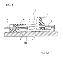
- a known contact 1 is a flat and having a substantially H-shape.
- the contact 1 includes contact arms 2 and 3 , a pivot 4 , a lever 5 , and a base 6 .
- an actuator 7 is turned clockwise, the lever 5 is displaced upward by a cam 8 , and the pivot 4 of the contact 1 is elastically deformed. Thereby, a flat cable 9 is clamped between the contact arms 2 and 3 , and is electrically connected to the contact 1 .
- the contact arm 2 and the lever 5 form one beam, and the contact arm 3 and the lever 6 also form one beam. Therefore, in order to reliably clamp the flat cable 9 between the contact arms 2 and 3 , the displacement of the lever 5 caused by the elastic deformation of the pivot 4 , produced by the operation of the actuator 7 , must be transmitted efficiently to the contact arm 2 .
- the lever 5 is displaced upward by the operation of the actuator 7 , the displacement of the contact arm 2 is restricted by the contact of the contact arm 2 with the flat cable 9 .
- the contact arm 2 is subjected to a reaction force from the flat cable 9 , so that the lower portion of the pivot 4 is raised, and lifts from a printed wiring board 100 .
- the displacement of the contact arm 2 becomes smaller than the displacement inherently produced in the contact arm 2 by the operation of the actuator 7 , along with the elastic deformation produced in the contact arm 2 and the lever 5 .
- the force for pressing the contact arm 2 against the flat cable 9 (referred to as a contact pressure) may be insufficient
- the distance from the pivot 4 to the point of application of the force in the actuator 7 is increased by lengthening the lever 5 to increase the clamping force for the flat cable 9 between the contact arms 2 and 3 , or the rigidity of the lever 5 is enhanced.
- the size of the contact 1 is increased, or the length in the front-back direction thereof is increased.
- the connector especially requiring a large mounting area on the printed wiring board 100 is also required to be made small in size.
- the increased size and rigidity of the contact 1 are unfavorable because they hinder the decrease in size of connector.
- the rigidity of the lever 5 is enhanced, the force required for the operation of the actuator 7 increases, so that the operability of the actuator 7 may be degraded.
- the connector is required to be formed so that the height, thereof in the state of being mounted on the printed wiring board 100 , is decreased as far as possible (this is called low-profile).
- the conventional flat and substantially H-shaped contacts are also formed so as to meet this requirement.
- the lever 5 is lengthened, the displacement on the rear end side of the lever 5 at the time when the lever 5 is operated by the actuator 7 increases, which hinders the contact from being low-profile.
- the contact 1 , the cam 8 of the actuator 7 , and the flat cable 9 vary in dimensions.
- the variations in the gap between the lever 5 and the base 6 of the contact 1 and the variations in dimension in the major axis direction of the cam 8 , the upward displacement of the lever 5 at the time when the actuator 7 is operated varies.
- the variations in the gap between the contact arms 2 and 3 of the contact 1 the displacement of the contact arm 2 caused by the displacement of the lever 5 varies.
- the variations in thickness of the flat cable 9 also lead to the variations in the relative displacement of the contact arm 2 with respect to the flat cable 9 .
- the variations in these dimensions are amplified according to the lengths (lever ratio) of the contact arms 2 and 3 and the lever 5 .
- the variations in these dimensions lead to the variations in contact pressure of the contact arm 2 against the flat cable 9 for each contact 1 or each connector. If the contact pressure is insufficient, the flat cable 9 may not be clamped reliably by the contact 1 . Also, if the contact pressure is excessive, the surface of the contact point of the contact 1 may roughen and electrical conductivity may become impaired. In the case where the contact pressure is excessive, the contact arm 2 and the lever 5 may be deformed plastically, exceeding the elastic deformation zone. In this case, when the flat cable 9 , having been clamed by the contact 1 , is unclamped by the operation of the actuator 7 , for example, at the time of maintenance, the gap between the contact arms 2 and 3 does not widen sufficiently.
- the flat cable 9 may interfere with the contact arms 2 and 3 .
- the lever 5 has been deformed plastically, when the flat cable 9 is inserted between the contact arms 2 and 3 again after being unclamped, and is clamped by operating the actuator 7 , the contact arms 2 and 3 may not exert a sufficient clamping force on the flat cable 9 .
- An object of the present invention is to provide an electrical connector capable of exerting a necessary and sufficient clamping force on a flat cable to reliably provide electrical conductivity while the connector is low-profile
- the electrical connector to electrically connect a flexible flat cable to a printed wiring board includes a housing made of an insulating material and having a cavity into which an end portion of the flat cable is inserted, an actuator having a cam, and a contact.
- the contact accommodated in the housing includes a base of the contact fixed to the housing and electrically connected to the printed wiring board, a lever extending from the base of the contact, a contact beam provided with a support arm that is supported by the lever, and a pressing arm projecting from the base toward the cam of the actuator.
- the cam of the actuator presses one end of the contact beam in a direction away from the printed wiring board while pressing the pressing arm and another end of the contact beam in a direction toward to the printed wiring board when a change-over operation of the contact to the clamping state is performed, the clamping state where the contact clamps end portion of the flat cable and thereby electrically connects to the printed wiring board.
- FIG. 1A is a plan view a connector according to the present invention.
- FIG. 1B is a front view of the connector of FIG. 1 according to the present invention.
- FIG. 1C is a side view of the connector of FIG. 1 according to the present invention.
- FIG. 2A is a cross-sectional view taken along the line 2 - 2 of FIG. 1A ;
- FIG. 2B is a cross-sectional view of the connector showing a state in which the deformation of a contact produced by an actuator is completed, and a flat cable is clamped;
- FIG. 3A is a cross-sectional of the connector view showing a case where a part to be pressed is deformed less than in the case shown in FIG. 2B ;
- FIG. 3B is a cross-sectional view of the connector showing a case where the part to be pressed is deformed more than in the case shown in FIG. 2B ;
- FIG. 4 is a cross-sectional view of the connector showing another example of the shape of a part to be pressed.
- FIG. 5 is a cross-sectional view of a known conventional electrical connector.
- a connector (electrical connector) 10 is mounted on a printed wiring board 100 to electrically connect a flat cable 200 to the printed wiring board 100 by inserting an end portion of the flat cable 200 .
- the side on which the connector 10 is mounted on the printed wiring board 100 (the lower side in FIG. 1C ) is referred to as the lower side
- the side on which the flat cable 200 is inserted (the left side in FIG. 1C ) is referred to as the front side.
- the connector 10 includes a housing 11 , a plurality of contacts 20 accommodated in the housing 11 , and an actuator 12 for operating these contacts 20 .
- the housing 11 and the actuator 12 are each made of an insulating material, such as a resin.
- the contact 20 is formed by stamping a thin plate made of a conductive material such as a copper alloy.
- a cavity 30 is formed so that the end portion of the flat cable 200 may be inserted into this cavity 30 .
- the cavity 30 is open in a slit form.
- the plurality of contacts 20 for making electrical connection with conductors in the end portion of the flat cable 200 are arranged in one row.
- the contacts 20 are arranged in the direction in which the slit-form cavity 30 is continuous (the longitudinal direction of the housing 11 ).
- the contacts 20 are press fitted into the housing 11 .
- the actuator 12 is made of an insulating material, such as a resin, like the housing 11 , and is provided on the rear end side on the upper surface of the housing 11 .
- the actuator 12 extends in the longitudinal direction (the width direction) of the housing 11 , and pins 12 a provided in both end portions thereof are pivotally mounted on the housing 11 , so that the actuator 12 can rotate in a plane that is perpendicular to the surface of the printed wiring board 100 and includes the front-back direction of the housing 11 .
- the actuator 12 has a camshaft 12 b extending along the rotating shaft thereof, and the camshaft 12 b is formed with cams 40 at positions corresponding to each of the contacts 20 .
- the cam 40 is eccentrically provided with respect to the rotating center C (that is, the pin 12 a ) of the actuator 12 .
- the cam 40 has a substantially rectangular cross section that is slightly long in the front-back direction in a state in which a lever 41 of the actuator 12 is erected with respect to the housing 11 . In this state, the contacts 20 are opened so that when the flat cable 200 is inserted into the housing 11 , the insertion resistance caused by friction against the flat cable 200 is restrained.
- FIG. 2B when the actuator 12 is rotated, the cam 40 rotates to press the contact 20 , whereby the actuator 12 can change over the contact 20 from the opened state to a clamping state in which the contact 20 clamps the flat cable 200 .
- the cavity 30 is formed so as to be continuous to an intermediate portion in the front-back direction of the housing 11 so that the flat cable 200 is inserted into the cavity 30 .
- the rear portion of the cavity 30 is opened upward to form a space 31 for accommodating the contacts 20 and the actuator 12 .
- a recess 32 that engages with the contacts 20 to fix them is formed in the lower portion of the rear end portion of the cavity 30 .
- an engaging recess 32 a for engaging the contacts 20 is formed in the inner peripheral surface of the recess 32 .
- the contact 20 has a base 61 extending from the front of the housing 11 toward the rear thereof in a state in which the contact 20 is mounted in the housing 11 , a contact beam 62 for being electrically connected to the flat cable 200 , and a lever (deformed part) 63 formed between the base 61 and the contact beam 62 .
- the contact 20 is of a tuning fork type, such that the flat cable 200 is held and clamped between the contact beam 62 and the base 61 .
- a rear end section 61 a of the base 61 is inserted into the recess 32 of the housing 11 .
- the rear end section 61 a is provided with a protrusion 61 b corresponding to the engaging recess 32 a formed in the recess 32 .
- a stopper claw 61 d engaging with the front end portion on the bottom surface 11 b side of the housing 11 is formed to restrict the rearward movement of the contact 20 , in a state in which the rear end section 61 a of the base 61 is inserted into the recess 32 .
- the bottom surface of the front end section 61 c in the base 61 that is located forward of the stopper claw 61 d serves as a tine 65 , electrically connected to the conducive part of the printed wiring board 100 . That is to say, in this embodiment, the stopper claw 61 d and the tine 65 are continuously formed.
- the tine 65 is approximately flush with the bottom surface 11 b of the housing 11 , or slightly projects downward from the bottom surface 11 b of the housing 11 .
- the lever 63 is formed at a position closer to the rear end section 61 a than a middle point between the rear end section 61 a and the front end section 61 c of the base 61 , so as to extend upward from the base 61 .
- the contact beam 62 includes a support arm 62 a supported by the lever 63 , a lever arm 62 b extending from the support arm 62 a to the rear of the housing 11 , and a contact arm 62 c extending from the support arm 62 a to the front of the housing 11 for being electrically connected to the flat cable 200 .
- the support arm 62 a is a part in which the lever 63 joins with the contact beam 62 .
- the lever arm 62 b is arranged above the cam 40 of the actuator 12 .
- the lever arm 62 b is shorter than the contact arm 62 c , and is formed so as not to project rearward from the rear end section 61 a of the base 61 .
- the contact arm 62 c is formed so as to extend obliquely downward from the support arm 62 a.
- the cam 40 comes into contact with the lower surface of the lever arm 62 b of the contact beam 62 , and presses the lever arm 62 b upward.
- the lever 63 is elastically deformed so as to fall down forward, because it has a cross-sectional area smaller than that of the contact beam 62 , whereby the contact arm 62 c of the contact beam 62 is displaced downward.
- the contact arm 62 c being displaced downward, is pushed against the flat cable 200 , after being inserted into the cavity 30 , the contact arm 62 c is electrically connected to the flat cable 200 .
- the contact 20 further includes a pressing arm 64 , which is subjected to a downward pressing force from the cam 40 of the actuator 12 , under the cam 40 of the actuator 12 .
- the pressing arm 64 is provided in the vicinity of the joint portion of the base 61 and the lever 63 .
- the pressing arm 64 can have a substantially inverse L shape consisting of, for example, a columnar section 64 a extending upward from a position at the rear of the joint portion of the base 61 and the lever 63 , and a beam section 64 b extending from the tip end of the columnar section 64 a toward the rear.
- the housing 11 includes a stopper 52 , which restricts the downward displacement exceeding a fixed value of the beam section 64 b , under the beam section 64 b of the pressing arm 64 .
- An upper surface 52 a of the stopper 52 is formed so that a gap between the upper surface 52 a and the beam section 64 b has a predetermined dimension.
- the pressing force of the cam 40 of the actuator 12 is distributed and applied to not only the beam section 64 b , but also the stopper 52 . Thereby, the force acting on the beam section 64 b is reduced.
- the beam section 64 b may be plastically deformed if the displacement of the beam section 64 b becomes excessive. However, this plastic deformation can be prevented by providing the stopper 52 .
- the displacement of the contact 20 becomes the displacement to be produced inherently by the operation amount of the actuator 12 , so that the flat cable 200 can be pressed reliably.
- the base 61 can be prevented from lifting without lengthening the contact beam 62 , and the connector 10 is not hindered from being low-profile.
- the deformation state of the beam section 64 b of the pressing arm 64 differs depending on the thickness S 1 of the flat cable 200 , the gap S 2 between the lever arm 62 b of the contact beam 62 and the beam section 64 b of the pressing arm 64 in the contact 20 , and the dimension S 3 in the major axis direction of the cam 40 of the actuator 12 .
- the cam 40 of the actuator 12 may not come into contact with the beam section 64 b of the pressing arm 64 . In such a case, the displacement of the beam section 64 b is also not produced. In this case, all of the pressing force generated by the cam 40 can be transmitted to the lever arm 62 b of the contact beam 62 , so that the flat cable 200 can be clamped reliably.
- the displacement of the lever arm 62 b produced by the cam 40 is reduced, and therefore the contact pressure applied to the flat cable 200 in the contact arm 62 c of the contact beam 62 can be reduced.
- the force applied to the beam section 64 b can also be distributed to the housing 11 .
- the pressing force generated by the cam 40 of the actuator 12 tends to become excessive.
- the beam section 64 b of the pressing arm 64 is deformed downward by the pressing force generated by the cam 40 of the actuator 12 , whereby the pressing force transmitted to the lever arm 62 b of the contact beam 62 can be reduced, and the contact pressure in the contact arm 62 c can be lowered.
- the force applied to the beam section 64 b can also be distributed to the housing 11 .
- the pressing arm 64 in the contact 20 , the pressing force of the cam 40 of the actuator 12 can be transmitted to the base 61 through the pressing arm 64 .
- the deformation of the base 61 such that the base 61 lifts up from a bottom surface 30 a of the cavity 30 , can be restrained. Therefore, the flat cable 200 is clamped reliably by the contact 20 , and the electrical conduction between the contact 20 and the flat cable 200 can be achieved reliably.
- the elastic deformation of the pressing arm 64 the range of variations in the contact pressure of the contact arm 62 c of the contact beam 62 caused by the variations in the thickness S 1 , the gap S 2 , the dimension S 3 , and the like can be made narrow. That is to say, the variations in the thickness S 1 , the gap S 2 , the dimension S 3 , and the like are permitted.
- the contact pressure of the contact arm 62 c can be effectively prevented from becoming excessive. Therefore, the plastic deformation of the contact 20 that may be produced as the result of excessive contact pressure can be prevented. Accordingly, the durability of the contact 20 can be enhanced, while the contact 20 clamps the flat cable 200 reliably.
- the contact 20 is of a tuning fork type shape, such that the connector 10 can be low-profile.
- the length of the lever arm 62 b is set so as to be shorter than the contact arm 62 c and such that the lever arm 62 b does not project rearward from the rear end section 61 a of the base 61 . Since the contact 20 can clamp the flat cable 200 reliably without lengthening the lever arm 62 b , the displacement of the lever arm 62 b at the time when the lever arm 62 b is operated by the actuator 12 is also small, so that the connector 10 is not hindered from being low-profile. Also, it is unnecessary to increase the rigidity of the lever arm 62 b to prevent the lift of the base 61 , and the operability of the actuator 12 is not degraded as the result of the increase in force necessary for the operation of the actuator 12 .
- the pressing arm 64 can be made a block-shaped convex part that is not elastically deformed by the operation of the actuator 12 .
- a beam section 64 b ′ may be formed into a shape extending toward the front of the housing 11 with respect to a columnar section 64 a ′ of a pressing arm 64 ′.
- the columnar section 64 a ′ of the pressing arm 64 ′ may have a shape extending obliquely rearward from the base 61 .
- the actuator 12 is of a so-called back flip type in the embodiment shown, such that the actuator 12 rotates on the rear side with respect to the insertion direction of the flat cable 200
- the actuator 12 can also be of a front flip type, such that the actuator 12 rotates on the front side with respect to the insertion direction of the flat cable 200
- the position of the actuator 12 is not limited to the rear end side of the housing 11 , and the actuator 12 may be provided on the front end side or the like of the housing 11 .
Landscapes
- Coupling Device And Connection With Printed Circuit (AREA)
Abstract
Description
Claims (11)
Applications Claiming Priority (3)
| Application Number | Priority Date | Filing Date | Title |
|---|---|---|---|
| JP2007153299A JP4575402B2 (en) | 2007-06-08 | 2007-06-08 | Electrical connector |
| JP2007/153299 | 2007-06-08 | ||
| PCT/JP2008/060450 WO2008149977A1 (en) | 2007-06-08 | 2008-06-06 | Electric connector |
Related Parent Applications (1)
| Application Number | Title | Priority Date | Filing Date |
|---|---|---|---|
| PCT/JP2008/060450 Continuation WO2008149977A1 (en) | 2007-06-08 | 2008-06-06 | Electric connector |
Publications (2)
| Publication Number | Publication Date |
|---|---|
| US20100081312A1 US20100081312A1 (en) | 2010-04-01 |
| US7901232B2 true US7901232B2 (en) | 2011-03-08 |
Family
ID=40093781
Family Applications (1)
| Application Number | Title | Priority Date | Filing Date |
|---|---|---|---|
| US12/633,542 Active US7901232B2 (en) | 2007-06-08 | 2009-12-08 | Electrical connector for a flexible flat cable |
Country Status (7)
| Country | Link |
|---|---|
| US (1) | US7901232B2 (en) |
| JP (1) | JP4575402B2 (en) |
| KR (1) | KR101125984B1 (en) |
| CN (1) | CN101711442A (en) |
| MY (1) | MY147619A (en) |
| TW (1) | TWM341958U (en) |
| WO (1) | WO2008149977A1 (en) |
Cited By (2)
| Publication number | Priority date | Publication date | Assignee | Title |
|---|---|---|---|---|
| US20130288511A1 (en) * | 2012-03-15 | 2013-10-31 | Omron Corporation | Connector |
| US20160380368A1 (en) * | 2015-06-26 | 2016-12-29 | Panasonic Intellectual Property Management Co., Ltd. | Connector and connector assembly including the same |
Families Citing this family (10)
| Publication number | Priority date | Publication date | Assignee | Title |
|---|---|---|---|---|
| KR101412924B1 (en) | 2008-04-22 | 2014-06-26 | 현대자동차주식회사 | Cable connector |
| JP4938113B2 (en) * | 2010-06-29 | 2012-05-23 | 日本航空電子工業株式会社 | connector |
| CN102694286A (en) * | 2012-04-23 | 2012-09-26 | 昆山嘉华电子有限公司 | Flexible circuit board connector |
| JP6051628B2 (en) * | 2012-07-06 | 2016-12-27 | 第一精工株式会社 | Connector device |
| DE102012222364A1 (en) * | 2012-12-05 | 2014-06-05 | E.G.O. Elektro-Gerätebau GmbH | Connector and device with such a connector |
| CN103457069A (en) * | 2013-08-20 | 2013-12-18 | 太仓天策信息技术咨询有限公司 | Electric connector assembly |
| CN103441357B (en) * | 2013-08-20 | 2015-12-02 | 太仓天策信息技术咨询有限公司 | Electric connector |
| JP6526590B2 (en) * | 2016-03-15 | 2019-06-05 | ヒロセ電機株式会社 | Flat type conductor electrical connector |
| JP6712388B2 (en) * | 2017-01-27 | 2020-06-24 | 日本圧着端子製造株式会社 | Housing and connector |
| JP7033727B2 (en) * | 2017-08-09 | 2022-03-11 | パナソニックIpマネジメント株式会社 | connector |
Citations (5)
| Publication number | Priority date | Publication date | Assignee | Title |
|---|---|---|---|---|
| US4778403A (en) * | 1987-07-15 | 1988-10-18 | Elco Corporation | Zero insertion force connector |
| US7172446B1 (en) | 2005-08-25 | 2007-02-06 | I-Pex Co., Ltd. | Electrical connector |
| JP2007265851A (en) | 2006-03-29 | 2007-10-11 | Molex Inc | Connector for cable |
| JP2007287398A (en) | 2006-04-13 | 2007-11-01 | Molex Inc | Cable connector |
| JP2008108458A (en) | 2006-10-23 | 2008-05-08 | Omron Corp | connector |
Family Cites Families (5)
| Publication number | Priority date | Publication date | Assignee | Title |
|---|---|---|---|---|
| US7172466B2 (en) * | 2001-04-05 | 2007-02-06 | Ortronics, Inc. | Dual reactance low noise modular connector insert |
| JP2004178959A (en) * | 2002-11-27 | 2004-06-24 | D D K Ltd | Connector |
| JP4100624B2 (en) * | 2002-12-25 | 2008-06-11 | 第一電子工業株式会社 | connector |
| JP4223323B2 (en) * | 2003-05-14 | 2009-02-12 | 京セラエルコ株式会社 | connector |
| JP4558562B2 (en) * | 2005-04-11 | 2010-10-06 | 第一電子工業株式会社 | connector |
-
2007
- 2007-06-08 JP JP2007153299A patent/JP4575402B2/en active Active
-
2008
- 2008-04-18 TW TW097206635U patent/TWM341958U/en not_active IP Right Cessation
- 2008-06-06 KR KR1020097025658A patent/KR101125984B1/en not_active Expired - Fee Related
- 2008-06-06 WO PCT/JP2008/060450 patent/WO2008149977A1/en not_active Ceased
- 2008-06-06 CN CN200880019331A patent/CN101711442A/en active Pending
- 2008-06-06 MY MYPI20095020A patent/MY147619A/en unknown
-
2009
- 2009-12-08 US US12/633,542 patent/US7901232B2/en active Active
Patent Citations (8)
| Publication number | Priority date | Publication date | Assignee | Title |
|---|---|---|---|---|
| US4778403A (en) * | 1987-07-15 | 1988-10-18 | Elco Corporation | Zero insertion force connector |
| US7172446B1 (en) | 2005-08-25 | 2007-02-06 | I-Pex Co., Ltd. | Electrical connector |
| JP2007059217A (en) | 2005-08-25 | 2007-03-08 | I-Pex Co Ltd | Connector device |
| JP2007265851A (en) | 2006-03-29 | 2007-10-11 | Molex Inc | Connector for cable |
| JP2007287398A (en) | 2006-04-13 | 2007-11-01 | Molex Inc | Cable connector |
| US20090298319A1 (en) | 2006-04-13 | 2009-12-03 | Molex Incorporated | Flat Cable Connector |
| JP2008108458A (en) | 2006-10-23 | 2008-05-08 | Omron Corp | connector |
| US20100087078A1 (en) | 2006-10-23 | 2010-04-08 | Omron Corporation | Connector |
Non-Patent Citations (1)
| Title |
|---|
| IPRP issued in co-pending International Application No. PCT/JP2008/060450, dated Dec. 11, 2009, 6 pages. |
Cited By (4)
| Publication number | Priority date | Publication date | Assignee | Title |
|---|---|---|---|---|
| US20130288511A1 (en) * | 2012-03-15 | 2013-10-31 | Omron Corporation | Connector |
| US9166332B2 (en) * | 2012-03-15 | 2015-10-20 | Omron Corporation | Connector |
| US20160380368A1 (en) * | 2015-06-26 | 2016-12-29 | Panasonic Intellectual Property Management Co., Ltd. | Connector and connector assembly including the same |
| US9799974B2 (en) * | 2015-06-26 | 2017-10-24 | Panasonic Intellectual Property Management Co., Ltd. | Connector and connector assembly including the same |
Also Published As
| Publication number | Publication date |
|---|---|
| WO2008149977A1 (en) | 2008-12-11 |
| KR20100029196A (en) | 2010-03-16 |
| JP4575402B2 (en) | 2010-11-04 |
| JP2008305727A (en) | 2008-12-18 |
| CN101711442A (en) | 2010-05-19 |
| MY147619A (en) | 2012-12-31 |
| TWM341958U (en) | 2008-10-01 |
| KR101125984B1 (en) | 2012-03-20 |
| US20100081312A1 (en) | 2010-04-01 |
Similar Documents
| Publication | Publication Date | Title |
|---|---|---|
| US7901232B2 (en) | Electrical connector for a flexible flat cable | |
| JP3903338B2 (en) | FPC connector | |
| US7422472B2 (en) | Connector | |
| JP4484218B2 (en) | connector | |
| JP4479989B2 (en) | connector | |
| US7950952B2 (en) | FPC connector with rotating latch | |
| US20190044263A1 (en) | Connector | |
| EP0984519A2 (en) | Low profile electrical connector for a PGA package and terminals therefor | |
| US20110034056A1 (en) | Electrical Connector | |
| WO2011094701A2 (en) | Connector | |
| CN102761029B (en) | Connector | |
| EP1349240A2 (en) | Connector in which movement of contact portion of contact is guided by insulator | |
| US20100068919A1 (en) | Cable connector | |
| KR20080086824A (en) | Electrical connector | |
| US8123542B2 (en) | Contact and connector including the contact | |
| US20050020117A1 (en) | Socket for electronic part | |
| US6893278B2 (en) | Connector for connecting with flexible substrates | |
| US20090163067A1 (en) | Cable connector | |
| US20110143601A1 (en) | Connector | |
| KR100643181B1 (en) | connector | |
| JP4651501B2 (en) | Connector for cable connection | |
| US20080050945A1 (en) | Electrical socket connector with metal reinforced device between cover and base | |
| JP4528605B2 (en) | connector | |
| JP2006196356A (en) | Connector | |
| JP2010135085A (en) | Connector device |
Legal Events
| Date | Code | Title | Description |
|---|---|---|---|
| AS | Assignment |
Owner name: TYCO ELECTRONICS JAPAN G.K.,JAPAN Free format text: ASSIGNMENT OF ASSIGNORS INTEREST;ASSIGNOR:KODAIRA, YOSHIHIKO;REEL/FRAME:023629/0057 Effective date: 20091006 Owner name: TYCO ELECTRONICS JAPAN G.K., JAPAN Free format text: ASSIGNMENT OF ASSIGNORS INTEREST;ASSIGNOR:KODAIRA, YOSHIHIKO;REEL/FRAME:023629/0057 Effective date: 20091006 |
|
| STCF | Information on status: patent grant |
Free format text: PATENTED CASE |
|
| FPAY | Fee payment |
Year of fee payment: 4 |
|
| MAFP | Maintenance fee payment |
Free format text: PAYMENT OF MAINTENANCE FEE, 8TH YEAR, LARGE ENTITY (ORIGINAL EVENT CODE: M1552); ENTITY STATUS OF PATENT OWNER: LARGE ENTITY Year of fee payment: 8 |
|
| MAFP | Maintenance fee payment |
Free format text: PAYMENT OF MAINTENANCE FEE, 12TH YEAR, LARGE ENTITY (ORIGINAL EVENT CODE: M1553); ENTITY STATUS OF PATENT OWNER: LARGE ENTITY Year of fee payment: 12 |
|
| AS | Assignment |
Owner name: TE CONNECTIVITY JAPAN G.K., JAPAN Free format text: CHANGE OF NAME;ASSIGNOR:TYCO ELECTRONICS JAPAN G.K.;REEL/FRAME:069811/0353 Effective date: 20241001 |