US789973A - Pleasure-railway. - Google Patents
Pleasure-railway. Download PDFInfo
- Publication number
- US789973A US789973A US21127604A US1904211276A US789973A US 789973 A US789973 A US 789973A US 21127604 A US21127604 A US 21127604A US 1904211276 A US1904211276 A US 1904211276A US 789973 A US789973 A US 789973A
- Authority
- US
- United States
- Prior art keywords
- course
- horses
- truck
- railway
- pleasure
- Prior art date
- Legal status (The legal status is an assumption and is not a legal conclusion. Google has not performed a legal analysis and makes no representation as to the accuracy of the status listed.)
- Expired - Lifetime
Links
- 241000283086 Equidae Species 0.000 description 29
- 239000004020 conductor Substances 0.000 description 16
- 238000009408 flooring Methods 0.000 description 7
- 230000000694 effects Effects 0.000 description 2
- 230000005484 gravity Effects 0.000 description 2
- 241001465754 Metazoa Species 0.000 description 1
- 238000010276 construction Methods 0.000 description 1
- 230000009191 jumping Effects 0.000 description 1
- 230000000750 progressive effect Effects 0.000 description 1
- 230000000284 resting effect Effects 0.000 description 1
- 230000000979 retarding effect Effects 0.000 description 1
Images


Classifications
-
- A—HUMAN NECESSITIES
- A63—SPORTS; GAMES; AMUSEMENTS
- A63H—TOYS, e.g. TOPS, DOLLS, HOOPS OR BUILDING BLOCKS
- A63H18/00—Highways or trackways for toys; Propulsion by special interaction between vehicle and track
- A63H18/12—Electric current supply to toy vehicles through the track
Definitions
- My invention relates to that class of amusement devices which are commonly included under the head. of pleasure-railways, and
- a perfectly level course or trackway may be employed, and at the same time a variable speed may be imparted to the different moving parts.
- I employ a single motor or motor-truck which may itself be actuated at a variable rate of speed and provide means whereby the same may be independently thrown into operative relation with each of the horses or other moving parts.
- I also provide novel means whereby a movement may be imparted to the legs of the different horses to simulate the movement of a natural horse in running or galloping.
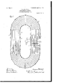
- Figure 1 is a plan view, partly broken away, of the course or trackway.
- v2 is a cross-section through part of the same.
- Fig. 3 is asectional elevation of thesame with parts broken away.
- Fig. 4 is an elevation, partly in section, showing an automobile, which may constitute one of the parts to be moved around the course.
- Figs. 5 and 6 are diagrammatic views showing the circuit connections of the le -actuating mechanism on the horses, and
- Fig. 7 is a sectional View showing the means for maintaining the tooth or engaging portion on the carriage of one of the horses raised and the circuit connections thereto.
- the purpose of this invention is to provide means whereby amusement may be afforded by a race upon independently-movable horses or other moving parts arranged to travel around a substantially level course or trackway.
- the framework of the apparatus consists of the uprights 3 4:, arranged in pairs about the course 2, the cross-beams 5 5, connecting each pair of said supports, the rails 6, connecting the cross-beams 5 and extending entirely around the course, the channels 7, resting upon and secured to the cross-beams 5,
- the flooring 8 which extends from thetops of the uprights 3 4 and is supported thereon and on the channels 7
- the flooring 8 is provided with a series of slots 9, extending in parallel relation entirely around the course or trackway 2, the said slots registering with corresponding slots 10 in the upper walls of the channels 7.
- Said channels are preferably rectangular in cross-section, as shown, the same having imperforate side and bottom walls and being closed throughout their top walls except for the slots 10 reof the same therethrough.
- each of said channels is mounted a carriage 11, the same being provided with rollers 12, 13, and 14, designed to engage the bottom, side, and top walls of the channel, so as to provide for the free passage
- Each of the carriages 11 has a rod or rods 15 extending upwardly therefrom and supporting a horse 1 or other movable part on the upper end.
- the said rod 15 extends through and is movable in the slot 10 in the channel 7 and the slot 9 in the flooring 8.
- Pivotally mounted in a recess or cavity 16 is a tooth or engaging part 17, which normally projects down below said carriage, has its shouldered portion facing to the rear, and an inclined wall or edge 18 facing toward the front.
- Said tooth projects down to a point within a plane beneath that in which the cross-beams 5 lie, so that the inclined wall or edge 18 thereof is adapted to be engaged by said cross-beams for raising the same and throwing it back into the carriage, to which it is pivoted. As soon as raised, however, said tooth returns to its normal position, as shown in Figs. 2 and 3 of the drawings, by gravity.
- the truck 20 has been shown as provided with an electric motor 22, which is supplied with current from a generator 23 through the conductor-rail 2 1 and a current-collector 25,carried by the truck.
- the rail 24 is connected, through the wires 26 and 27 and a controller 28,with one pole of the generator 23, and the rails 19 are connected, through the wire 29, with the other pole of said generator.
- the rails 19 and one pole of the generator 23 may be grounded. This, however, is a mere detail, which forms no part of my invention.
- the different horses will therefore travel at variable speeds around the course-sometimes faster, sometimes slower, than others. It is impossible to tell in advance which horse will cross the finish-line of the course first, and consequently considerable excitement and amusement may be afforded.
- the curves at the opposite ends of the course will have the effect of retarding some of the horses more than they will others; but as soon as a horse drops rearwardly it receives a fresh impulse from the motor, which starts it ahead of the others, so that while a slackening of speed is a temporary disadvantage it results in an advantage later, in the fact that it brings about an increased impulsive force thereon.
- Each of the legs 30, 31, 32, and 33 of each horse 1 is pivoted to the body of said horse, so that it is capable of independent movement.
- the legs 30 and 31 are provi ed, respectively.
- Each of the conductors 4O 41 is made up of sections which are insulated one from the other, so that for a short period of time the brushes 38 39 will move over live portions of said conductors, while during corresponding periods of time they will move over insulated portions thereof.
- the insulated portions of the conductor 40 are arranged above and between the uninsulated portions of the conductor 41.
- the carriage 11 is also provided with a contact spring or brush 42 on its opposite side, which moves in engagement with a conductor 43 on the inside of the channel 7.
- the conductor 43 is connected, through a wire 44, with one pole of an electric generator or other source of current, and the different sections of the conductors 40 and 41 are connected, through the wires 45 46 47, with the other pole of said generator.
- the solenoid 39 is connected, through the wire 46, with the brush 42.
- the solenoid 36 is connected, through the wire 47 ,-with the same brush.
- the solenoid 39 is connected, through the wire 48, with the brush 38-, and the solenoid 36 is connected, through the wire 45, with the brush 39
- the solenoid 39 will thus be deenergized and the solenoid 36 will be energized by the flow of current over the following path: wire 44, conductor 43, brush 42, wire 47 solenoid 36, wire 49, brush 39, conductor 41, and Wires 46 and 45.
- the solenoid 36 When the solenoid 36 is thus energized, it serves to swing the legs 30 and 31 upon their pivots. The result of this alternate energization and deenergization of the solenoids 36 and 39 will be to create a practically constant pivotal movement of the different legs of the horse,
- the automobile 59 may be of any suitable construction, the same being connected, through the rods or bars 60, with two of the carriages 11 in a manner similar to that in which the rods 15 are connected to a single carriage.
- the front axle 61 is mounted for pivotal movement, so that the automobile may be steered in its passage around the course 2.
- the arms '62 Secured to the axle 61 and extending downwardly and outwardly therefrom are the arms '62, the end of each of said arms being bifurcated, as shown.
- the branchesof said arms pass down through two of the slots 9 in the flooring 2 and are connected together at a point beneath said floor by the brace or connecting rod 63. Any curvature in the slots 9, through which the arms 62 extend, will cause a corresponding turning movement of the axle 61, and thus properly steer the automobile around the course.
- the rod or brace 63 being located beneath the flooring 2 does not come in contact with the walls of the slots 9, and consequently can cause no binding in said slots.
- I claim 1. In apleasure-railway, a plurality of parts arranged for independent movement along different paths around a course or trackway. and a traveling motor independent of but adapted to engage said parts for propelling them.
- a pleasure-railway a plurality of parts arranged for independent movement along a course or trackway, and a traveling motor movable beneath and adapted to independently engage said parts for propelling them.
- a plurality of parts arranged for independent movement along different paths around a course or trackway, a traveling motor independent thereof, engaging means on each of said moving parts, and a plurality of engaging means on said motor, respectively cooperating therewith.
- a traveling motor independent of but adapted to engage said parts for propelling them, and means for varying the speed of said motor.
- a plurality of parts arranged for independent movement along clifferent paths around a course or trackway, each having an engaging portion thereon, and an independently-movable motor-truck having an engaging portion thereon cooperating with those on said movable parts.
- a movable part arranged for movement along a course or trackway, an engaging portion thereon, an independently-movable motor-truck having an engaging portion thereon, cooperating with that on said movable part, and means for automatically tripping the engaging portion on said movable part out of the path of movement of that on said truck.
- a movable part arranged for movement along a course or trackway, a pivotally-mounted tooth projecting downwardly therefrom, and an independentlymovable motor-truck having an engaging portion thereon cooperating with said tooth.
- a movable part arranged for movement along a course or trackway, a pivotally mounted tooth projecting downwardly therefrom, an independentlymovable motor-truck having an elongated rack thereon cooperating with said tooth and means for automatically throwing said tooth out of and into engagement with said rack.
- a pleasure-railway a plurality of parts arranged for independent movement along a course or trackway, a pivotally-mounted tooth normally projecting downwardly from each of said parts, an independently-movable motortruck having a plurality of elongated racks thereon cooperating respectively with said teeth and means for intermittently throwing said teeth out of and into engagement with said racks.
- a pleasure-railway a plurality of parts arranged for independent movement along a course or trackway, a pivotally-mounted tooth normally projecting downwardly from each of said parts, an independentlymovable motor-truck having a plurality of elongated racks thereon cooperating respectively with said teeth, means for intermittently throwing said teeth out of and into engagement with said racks and means for varying the speed of said truck.
- a course or trackway made up of uprights, cross-beams connecting the same, a plurality of slotted channels supported upon said cross-beams and a flooring having slots therein communicating with said channels, in combination with carriages movable in said channels, rods or bars secured thereto and leading upwardly through said slots for supporting horses or other analogous devices, pivotally-mounted teeth, one on each of said carriages, normally projecting downwardly therefrom and adapted to engage said cross-beams, whereby the same are intermittently raised and lowered and an independ ently-movable motor-truck having a plurality of racks thereon cooperating with said teeth.
- a course or trackway made up of uprights, cross-beams connecting the same, rails secured to said crossbeams, a plurality of slotted channels supported upon said cross-beams and a flooring having slots therein communicating with said channels, in combination with carriages movable in said channels, rods or bars secured thereto and leading upwardly through said slots for supporting horses or other analogous devices, pivotally-mounted teeth, one on each of said carriages, normally projecting downwardly therefrom and adapted to engage said cross-beams, whereby the same are intermittently raised and lowered, and an independently-movable motor-truck having a plurality of racks thereon cooperating with said teeth and having rollers thereon adapted to engage said rails, as and for the purpose set forth.
- a horse or other animal body having pivoted legs and means for moving the same along a course or track- Way, in combination with means for moving said legs on their pivots, the said means consisting of a pair of solenoids having their cores connected respectively with said legs and means for automatically opening and closing an electric circuit to the solenoids, alternately.
- a moving part arranged for independent movement along a course or trackway, a pivotally mounted tooth thereon, a motor-truck having an engaging portion cooperating with said tooth for propelling said part, means for automatically moving said tooth intermittently out of the path of movement of said engaging portion, a catch for retaining said tooth in the latter position and means under control of the operator for throwing said catch into operation.
Landscapes
- Toys (AREA)
Description
No. 739,973. Y PA'TENTED MAY 16, 1905. G. K. HAETUNG.
PLEASURE RAILWAY.
APPLICATION FILED JUNHG. 1904.
3 SHEETS-SHEET l.
No. 789,978. PATENTEIQ MAY 16, 1905.
G. K. HARTUNG.
PLEASURE RAILWAY.
APPLICATION FILED JUNE 6. 1904.
3SHEETS-SHEET 2.
No. 799,973. PATENTED MAY 19, 1905. 9. K. HARTUNG.
PLEASURE RAILWAY.
APPLIOATION FILED JUNE 6, 1904.
3 SHEETS-SHEET 3.
Gaame 1f 52/121129.
@3391 M lttovmm s M NiT En STATES Patented May 16, 1905.
PATENT Trice.
PLEASURE-RAILWAY.
SPECIFICATION forming part of Letters Patent No. 789,973, dated May 16, 1905.
Application filed June 6, 1904. Serial No. 211,276.
To (ti/Z whom it iii/my concern.-
Be it known that I, Gus'rAvn K. HARTUNG, a subject of the Emperor of Germany, residing at the city of New York, in the borough of Bronx and State of New York, have invented certain new and useful Improvements in PleasureRailways, of which the following is a full, clear, and exact description.
My invention relates to that class of amusement devices which are commonly included under the head. of pleasure-railways, and
while the apparatus-is in one sense a railway of this kind its purpose is to provide means whereby a series of horses, carriages, or other moving parts are caused to travel at variable rates of speed around a course or trackway. Apparatus of this kind has heretofore been devised; but in all such devices which have come to my notice the progressive movement of the horses or other moving parts is caused by the action of gravity by an arrangement of inclines at various points along the course.
According to my invention a perfectly level course or trackway may be employed, and at the same time a variable speed may be imparted to the different moving parts.
I employ a single motor or motor-truck which may itself be actuated at a variable rate of speed and provide means whereby the same may be independently thrown into operative relation with each of the horses or other moving parts.
I also provide novel means whereby a movement may be imparted to the legs of the different horses to simulate the movement of a natural horse in running or galloping.
1 also provide means whereby any one or more of the horses or other moving parts may be disconnected from the motor or motortruck in the event that the speed thereof becomes too great for safety or that for any reason the rider desires to drop out of the race.
The details of my invention will hereinafter appear, and the novel features thereof will be set forth in the claims.
In the drawings forming part of the specification, Figure 1 is a plan view, partly broken away, of the course or trackway. Fig.
v2 is a cross-section through part of the same.
Fig. 3 is asectional elevation of thesame with parts broken away. Fig. 4 is an elevation, partly in section, showing an automobile, which may constitute one of the parts to be moved around the course. Figs. 5 and 6 are diagrammatic views showing the circuit connections of the le -actuating mechanism on the horses, and Fig. 7 is a sectional View showing the means for maintaining the tooth or engaging portion on the carriage of one of the horses raised and the circuit connections thereto.
Like reference-numerals indicate like parts in the different views.
The purpose of this invention is to provide means whereby amusement may be afforded by a race upon independently-movable horses or other moving parts arranged to travel around a substantially level course or trackway.
1 represents a series of horses each adapted to support a rider, as is common in this class of device; but it is obvious that for'the said horses any other suitable form of moving device may be employed. These horses are adapted to travel about a course or trackway 2, which in the present case has been shown substantially elliptical in shape and practically level. The particular shape of the course, however, isimrnaterial, and my invention may be carried out if the same is not arranged in a perfectly level position.
The framework of the apparatus consists of the uprights 3 4:, arranged in pairs about the course 2, the cross-beams 5 5, connecting each pair of said supports, the rails 6, connecting the cross-beams 5 and extending entirely around the course, the channels 7, resting upon and secured to the cross-beams 5,
and the flooring 8, which extends from thetops of the uprights 3 4 and is supported thereon and on the channels 7 The flooring 8 is provided with a series of slots 9, extending in parallel relation entirely around the course or trackway 2, the said slots registering with corresponding slots 10 in the upper walls of the channels 7. Said channels are preferably rectangular in cross-section, as shown, the same having imperforate side and bottom walls and being closed throughout their top walls except for the slots 10 reof the same therethrough.
ferred to. Within each of said channels is mounted a carriage 11, the same being provided with rollers 12, 13, and 14, designed to engage the bottom, side, and top walls of the channel, so as to provide for the free passage Each of the carriages 11 has a rod or rods 15 extending upwardly therefrom and supporting a horse 1 or other movable part on the upper end. The said rod 15 extends through and is movable in the slot 10 in the channel 7 and the slot 9 in the flooring 8. Pivotally mounted in a recess or cavity 16 is a tooth or engaging part 17, which normally projects down below said carriage, has its shouldered portion facing to the rear, and an inclined wall or edge 18 facing toward the front. Said tooth projects down to a point within a plane beneath that in which the cross-beams 5 lie, so that the inclined wall or edge 18 thereof is adapted to be engaged by said cross-beams for raising the same and throwing it back into the carriage, to which it is pivoted. As soon as raised, however, said tooth returns to its normal position, as shown in Figs. 2 and 3 of the drawings, by gravity.
Between the uprights 3 and 4 beneath the cross-beams 5 are mounted a pair of trackrails 19, upon which a motor-truck is adapted to travel. These rails 19 extend entirely around the course, and the truck 20 is provided for the purpose of propelling the horses or other moving parts 1. To this end the said truck is provided with a series of racks 21 or other analogous engaging parts, the said racks being located on said truck directly beneath the centers of each of the channels 7, so as to cooperate with the teeth 17, which project downwardly from the carriages 11. The truck 20 has been shown as provided with an electric motor 22, which is supplied with current from a generator 23 through the conductor-rail 2 1 and a current-collector 25,carried by the truck. The rail 24 is connected, through the wires 26 and 27 and a controller 28,with one pole of the generator 23, and the rails 19 are connected, through the wire 29, with the other pole of said generator. In lieu of the wire 29, however, it is obvious that the rails 19 and one pole of the generator 23 may be grounded. This, however, is a mere detail, which forms no part of my invention.
The operation of the apparatus is as follows: Assuming that the horses 1 are initially in the positions in which they are shown in Fig. 1 of the drawings, when current is turned onto the motor 22, which may be done through the opforward end of one of the racks 21 on the truck 20 into engagement with the tooth 17 on the carriage 11 of the rearmost, horse 1. When this takes place, an impulse is given to said carriage and to the horse mounted thereon and the same starts forward ahead of the truck 20 until the latter comes in contact with the tooth 17 on the carriage 11 of the next rearmost horse 1. The latter is then given a forward impulse, and this action is repeated until all of the horses have been put in motion. As the teeth or engaging portions 17 of the carriages of the different horses, however, come into contact with the different crossbeams 5, arranged about the course, said teeth will be automatically elevated and thrown out of the path of movement of the racks 21, with which they cooperate. At such times the racks gain slightly upon said horses; but as soon as the teeth 17 return to their normal positions they drop into engagement with one or the other of the rear teeth of the racks, and said horses are again impelled forwardly. The result will be that in the passage or movement of each horse around the course the truck 20 will be brought into operative relation therewith at different times and with diflerent degrees of force and speed, according to the number of other horses which said truck may happen to be in engagement with at the time. The different horses will therefore travel at variable speeds around the course-sometimes faster, sometimes slower, than others. It is impossible to tell in advance which horse will cross the finish-line of the course first, and consequently considerable excitement and amusement may be afforded. The curves at the opposite ends of the course will have the effect of retarding some of the horses more than they will others; but as soon as a horse drops rearwardly it receives a fresh impulse from the motor, which starts it ahead of the others, so that while a slackening of speed is a temporary disadvantage it results in an advantage later, in the fact that it brings about an increased impulsive force thereon.
Each of the legs 30, 31, 32, and 33 of each horse 1 is pivoted to the body of said horse, so that it is capable of independent movement.
.The legs 30 and 31 are provi ed, respectively,
with the arms 34 and 35, which are pivoted to opposite ends of the core of a solenoid 36, and the legs 32 and 33 are provided with arms 37 38, respectively, which are pivoted to the core of the solenoid 39. All these parts are mounted within the hollow body of each horse, and the action of the different solenoids causes movements of the difierent legs of. the horses to simulate the movements of a natural horses legs in the act of running. The solenoids 36 and 39 are alternately energized, and to effect this result I provide on the outside of each carriage 11 a pair of contact springs or brushes 38 and 39, arranged upon one side of .said carriage, one above the other. These springs or brushes are adapted to cooperate with the conductors 10 and 11, respectively, arranged within the channel 7. Each of the conductors 4O 41 is made up of sections which are insulated one from the other, so that for a short period of time the brushes 38 39 will move over live portions of said conductors, while during corresponding periods of time they will move over insulated portions thereof. The insulated portions of the conductor 40 are arranged above and between the uninsulated portions of the conductor 41. The carriage 11 is also provided with a contact spring or brush 42 on its opposite side, which moves in engagement with a conductor 43 on the inside of the channel 7. The conductor 43 is connected, through a wire 44, with one pole of an electric generator or other source of current, and the different sections of the conductors 40 and 41 are connected, through the wires 45 46 47, with the other pole of said generator. The solenoid 39 is connected, through the wire 46, with the brush 42. The solenoid 36 is connected, through the wire 47 ,-with the same brush. The solenoid 39 is connected, through the wire 48, with the brush 38-, and the solenoid 36 is connected, through the wire 45, with the brush 39 From this description it will be noted that the legs of each of the horses 1 will be automatically caused to move backwardly and forwardly upon their pivots by the make and break of the circuit connections to the solenoids 36 and 39, which is caused by the passage of the carriage 11, on which'each horse is mounted, through one of the channels 7that is to say, when the brush 38 is in contact with a live .portionof the conductor 40 the brush 39 will be in contact with an insulated portion of the conductor 41. The flow of current will then be from the source of supply to the wire 44, conductor 43, brush 42, wire 46, solenoid 39, wire 48, brush 38", conductor 40, and wires 47 and 45, back to the source of supply. When the solenoid is thus energized by the flow of current therethrough, the core thereof will be moved in one direction or the other, according to what its starting position was, and through the arms 37 and 38 will move the legs 32 and 34 around on their pivots. When the brush 38 passes upon an insulated portion of the conductor 40, the brush 39 at the same time passes upon a conducting portion of the conductor 41. The solenoid 39 will thus be deenergized and the solenoid 36 will be energized by the flow of current over the following path: wire 44, conductor 43, brush 42, wire 47 solenoid 36, wire 49, brush 39, conductor 41, and Wires 46 and 45. When the solenoid 36 is thus energized, it serves to swing the legs 30 and 31 upon their pivots. The result of this alternate energization and deenergization of the solenoids 36 and 39 will be to create a practically constant pivotal movement of the different legs of the horse,
' the legs 30 and 31 moving together in one direction and the legs 32 and 33 moving together in the opposite direction.
If for any reason it be desired to throw one or more of the horses 1 out of operation that is, to prevent the action of the propelling-motor truck 20 thereon-it is merely necessary for the operator to press the pushbutton 50, arranged at any convenient point on the horses body. The result of this action will be to close a circuit from a battery 51 over the wires 52 and 53 through an electromagnet 54, arranged at a convenient point on the carriage 11. The armature 55 of said magnet will be thereby attracted and throw outwardly a catch 56, which is connected thereto or forms part thereof. The said armature and catch are pivotally mounted at 57 and said catch is provided with a tooth or shoulder 58, which is adapted to engage the free end of the tooth 17, heretofore referred to. When said tooth 17 is thus engaged, it is held in the raised position to which it was moved by being brought into engagement with one of the cross-beams 5, and thus be held out of the path of movement of the racks 21 on the motor-truck 20. Said truck may thus pass by said tooth 17 and the carriage 11, on which it is mounted, without imparting any propelling action thereto. The result will be that the horse 1 will come to a standstill as soon as the momentum thereof dies out.
Instead of the horses 1 or in addition thereto I may use the automobile 59. (Shown in full lines in Fig. 4 of the drawings and in dotted lines in Figs. 1 and 2.) This automobile may be of any suitable construction, the same being connected, through the rods or bars 60, with two of the carriages 11 in a manner similar to that in which the rods 15 are connected to a single carriage. The front axle 61 is mounted for pivotal movement, so that the automobile may be steered in its passage around the course 2. Secured to the axle 61 and extending downwardly and outwardly therefrom are the arms '62, the end of each of said arms being bifurcated, as shown. The branchesof said arms pass down through two of the slots 9 in the flooring 2 and are connected together at a point beneath said floor by the brace or connecting rod 63. Any curvature in the slots 9, through which the arms 62 extend, will cause a corresponding turning movement of the axle 61, and thus properly steer the automobile around the course. The rod or brace 63 being located beneath the flooring 2 does not come in contact with the walls of the slots 9, and consequently can cause no binding in said slots.
In order to prevent the truck 20 from jumping the track upon which the wheels thereof move, I provide the rollers 64 on said truck, which move in contact with the rails 6.
While I have shown and described the au- 11, the horses 1, the automobiles 59, or any equivalent thereof.
Having described my invention, I claim 1. In apleasure-railway, a plurality of parts arranged for independent movement along different paths around a course or trackway. and a traveling motor independent of but adapted to engage said parts for propelling them.
2. In a pleasure-railway, a plurality of parts arranged for independent movement along a course or trackway, and a traveling motor movable beneath and adapted to independently engage said parts for propelling them.
3. In apleasure-railway, a plurality of parts arranged for independent movement along different paths around a course or trackway, a traveling motor independent thereof, engaging means on each of said moving parts, and a plurality of engaging means on said motor, respectively cooperating therewith.
4. In a pleasure-railway, a plurality of parts arranged for independent movement along different paths around a course or trackway, a traveling motor independent of but adapted to engage said parts for propelling them, and means for varying the speed of said motor.
5. In a pleasure-railway, a plurality of parts arranged for independent movement along clifferent paths around a course or trackway, each having an engaging portion thereon, and an independently-movable motor-truck having an engaging portion thereon cooperating with those on said movable parts.
6. In a pleasure-railway, a movable part arranged for movement along a course or trackway, an engaging portion thereon, an independently-movable motor-truck having an engaging portion thereon, cooperating with that on said movable part, and means for automatically tripping the engaging portion on said movable part out of the path of movement of that on said truck.
7. In a pleasure-railway, a movable part arranged for movement along a course or trackway, a pivotally-mounted tooth projecting downwardly therefrom, and an independentlymovable motor-truck having an engaging portion thereon cooperating with said tooth.
8. In a pleasure-railway, a movable part arranged for movement along a course or trackway, a pivotally mounted tooth projecting downwardly therefrom, an independentlymovable motor-truck having an elongated rack thereon cooperating with said tooth and means for automatically throwing said tooth out of and into engagement with said rack.
9. In a pleasure-railway, a plurality of parts arranged for independent movement along a course or trackway, a pivotally-mounted tooth normally projecting downwardly from each of said parts, an independently-movable motortruck having a plurality of elongated racks thereon cooperating respectively with said teeth and means for intermittently throwing said teeth out of and into engagement with said racks.
10. In a pleasure-railway, a plurality of parts arranged for independent movement along a course or trackway, a pivotally-mounted tooth normally projecting downwardly from each of said parts, an independentlymovable motor-truck having a plurality of elongated racks thereon cooperating respectively with said teeth, means for intermittently throwing said teeth out of and into engagement with said racks and means for varying the speed of said truck.
11. In a pleasure-railway, a course or trackway made up of uprights, cross-beams connecting the same, a plurality of slotted channels supported upon said cross-beams and a flooring having slots therein communicating with said channels, in combination with carriages movable in said channels, rods or bars secured thereto and leading upwardly through said slots for supporting horses or other analogous devices, pivotally-mounted teeth, one on each of said carriages, normally projecting downwardly therefrom and adapted to engage said cross-beams, whereby the same are intermittently raised and lowered and an independ ently-movable motor-truck having a plurality of racks thereon cooperating with said teeth.
12. In a pleasure-railway, a course or trackway made up of uprights, cross-beams connecting the same, rails secured to said crossbeams, a plurality of slotted channels supported upon said cross-beams and a flooring having slots therein communicating with said channels, in combination with carriages movable in said channels, rods or bars secured thereto and leading upwardly through said slots for supporting horses or other analogous devices, pivotally-mounted teeth, one on each of said carriages, normally projecting downwardly therefrom and adapted to engage said cross-beams, whereby the same are intermittently raised and lowered, and an independently-movable motor-truck having a plurality of racks thereon cooperating with said teeth and having rollers thereon adapted to engage said rails, as and for the purpose set forth.
13. In a pleasure-railway, a horse or other animal body, having pivoted legs and means for moving the same along a course or track- Way, in combination with means for moving said legs on their pivots, the said means consisting of a pair of solenoids having their cores connected respectively with said legs and means for automatically opening and closing an electric circuit to the solenoids, alternately.
14:. In a pleasure-railway, a moving part arranged for independent movement along a course or trackway, a pivotally mounted tooth thereon, a motor-truck having an engaging portion cooperating with said tooth for propelling said part, means for automatically moving said tooth intermittently out of the path of movement of said engaging portion, a catch for retaining said tooth in the latter position and means under control of the operator for throwing said catch into operation. y
15. In a pleasure-railway, a moving part arranged for independent movement along a GUSTAVE K. HARTUNG.
Witnesses:
WM. M. STOOKBRIDGE, FRANK S. OBER.
Priority Applications (1)
| Application Number | Priority Date | Filing Date | Title |
|---|---|---|---|
| US21127604A US789973A (en) | 1904-06-06 | 1904-06-06 | Pleasure-railway. |
Applications Claiming Priority (1)
| Application Number | Priority Date | Filing Date | Title |
|---|---|---|---|
| US21127604A US789973A (en) | 1904-06-06 | 1904-06-06 | Pleasure-railway. |
Publications (1)
| Publication Number | Publication Date |
|---|---|
| US789973A true US789973A (en) | 1905-05-16 |
Family
ID=2858466
Family Applications (1)
| Application Number | Title | Priority Date | Filing Date |
|---|---|---|---|
| US21127604A Expired - Lifetime US789973A (en) | 1904-06-06 | 1904-06-06 | Pleasure-railway. |
Country Status (1)
| Country | Link |
|---|---|
| US (1) | US789973A (en) |
Cited By (1)
| Publication number | Priority date | Publication date | Assignee | Title |
|---|---|---|---|---|
| US5453053A (en) * | 1993-07-15 | 1995-09-26 | The Walt Disney Company | Amusement ride having spinning passenger cars |
-
1904
- 1904-06-06 US US21127604A patent/US789973A/en not_active Expired - Lifetime
Cited By (1)
| Publication number | Priority date | Publication date | Assignee | Title |
|---|---|---|---|---|
| US5453053A (en) * | 1993-07-15 | 1995-09-26 | The Walt Disney Company | Amusement ride having spinning passenger cars |
Similar Documents
| Publication | Publication Date | Title |
|---|---|---|
| US1591566A (en) | Amusement device | |
| US2218164A (en) | Game apparatus | |
| US872253A (en) | Amusement apparatus. | |
| US789973A (en) | Pleasure-railway. | |
| US2180448A (en) | Amusement device | |
| US1890137A (en) | Amusement railway | |
| US647166A (en) | Starting device for race-courses. | |
| US583109A (en) | Daniels | |
| US1555028A (en) | Amusement device | |
| US834016A (en) | Amusement apparatus. | |
| US1527893A (en) | Pleasure railway | |
| US1097160A (en) | Railway system. | |
| US912004A (en) | Racing amusement apparatus. | |
| US2507994A (en) | Starting apparatus for race tracks | |
| US997071A (en) | Mechanical toboggan-slide. | |
| US1217145A (en) | Race-game apparatus. | |
| US737257A (en) | Electric field game. | |
| US1770068A (en) | Lure carrier | |
| US1533795A (en) | Race game | |
| US1960395A (en) | Amusement apparatus | |
| US3019740A (en) | Amusement rides | |
| US867180A (en) | Vehicle-controlling apparatus. | |
| US1474335A (en) | Amusement apparatus | |
| US2424354A (en) | Amusement device | |
| US1450669A (en) | Amusement apparatus |