US7895716B2 - Adjustable spiral sleeve for protecting lines - Google Patents
Adjustable spiral sleeve for protecting lines Download PDFInfo
- Publication number
- US7895716B2 US7895716B2 US11/723,950 US72395007A US7895716B2 US 7895716 B2 US7895716 B2 US 7895716B2 US 72395007 A US72395007 A US 72395007A US 7895716 B2 US7895716 B2 US 7895716B2
- Authority
- US
- United States
- Prior art keywords
- strip
- wrapping
- lines
- spiral sleeve
- support strip
- Prior art date
- Legal status (The legal status is an assumption and is not a legal conclusion. Google has not performed a legal analysis and makes no representation as to the accuracy of the status listed.)
- Active, expires
Links
Images


Classifications
-
- F—MECHANICAL ENGINEERING; LIGHTING; HEATING; WEAPONS; BLASTING
- F16—ENGINEERING ELEMENTS AND UNITS; GENERAL MEASURES FOR PRODUCING AND MAINTAINING EFFECTIVE FUNCTIONING OF MACHINES OR INSTALLATIONS; THERMAL INSULATION IN GENERAL
- F16L—PIPES; JOINTS OR FITTINGS FOR PIPES; SUPPORTS FOR PIPES, CABLES OR PROTECTIVE TUBING; MEANS FOR THERMAL INSULATION IN GENERAL
- F16L3/00—Supports for pipes, cables or protective tubing, e.g. hangers, holders, clamps, cleats, clips, brackets
- F16L3/26—Supports for pipes, cables or protective tubing, e.g. hangers, holders, clamps, cleats, clips, brackets specially adapted for supporting the pipes all along their length, e.g. pipe channels or ducts
-
- F—MECHANICAL ENGINEERING; LIGHTING; HEATING; WEAPONS; BLASTING
- F16—ENGINEERING ELEMENTS AND UNITS; GENERAL MEASURES FOR PRODUCING AND MAINTAINING EFFECTIVE FUNCTIONING OF MACHINES OR INSTALLATIONS; THERMAL INSULATION IN GENERAL
- F16L—PIPES; JOINTS OR FITTINGS FOR PIPES; SUPPORTS FOR PIPES, CABLES OR PROTECTIVE TUBING; MEANS FOR THERMAL INSULATION IN GENERAL
- F16L3/00—Supports for pipes, cables or protective tubing, e.g. hangers, holders, clamps, cleats, clips, brackets
- F16L3/14—Hangers in the form of bands or chains
-
- F—MECHANICAL ENGINEERING; LIGHTING; HEATING; WEAPONS; BLASTING
- F16—ENGINEERING ELEMENTS AND UNITS; GENERAL MEASURES FOR PRODUCING AND MAINTAINING EFFECTIVE FUNCTIONING OF MACHINES OR INSTALLATIONS; THERMAL INSULATION IN GENERAL
- F16L—PIPES; JOINTS OR FITTINGS FOR PIPES; SUPPORTS FOR PIPES, CABLES OR PROTECTIVE TUBING; MEANS FOR THERMAL INSULATION IN GENERAL
- F16L57/00—Protection of pipes or objects of similar shape against external or internal damage or wear
- F16L57/06—Protection of pipes or objects of similar shape against external or internal damage or wear against wear
-
- H—ELECTRICITY
- H02—GENERATION; CONVERSION OR DISTRIBUTION OF ELECTRIC POWER
- H02G—INSTALLATION OF ELECTRIC CABLES OR LINES, OR OF COMBINED OPTICAL AND ELECTRIC CABLES OR LINES
- H02G3/00—Installations of electric cables or lines or protective tubing therefor in or on buildings, equivalent structures or vehicles
- H02G3/30—Installations of cables or lines on walls, floors or ceilings
-
- Y—GENERAL TAGGING OF NEW TECHNOLOGICAL DEVELOPMENTS; GENERAL TAGGING OF CROSS-SECTIONAL TECHNOLOGIES SPANNING OVER SEVERAL SECTIONS OF THE IPC; TECHNICAL SUBJECTS COVERED BY FORMER USPC CROSS-REFERENCE ART COLLECTIONS [XRACs] AND DIGESTS
- Y10—TECHNICAL SUBJECTS COVERED BY FORMER USPC
- Y10T—TECHNICAL SUBJECTS COVERED BY FORMER US CLASSIFICATION
- Y10T24/00—Buckles, buttons, clasps, etc.
- Y10T24/14—Bale and package ties, hose clamps
-
- Y—GENERAL TAGGING OF NEW TECHNOLOGICAL DEVELOPMENTS; GENERAL TAGGING OF CROSS-SECTIONAL TECHNOLOGIES SPANNING OVER SEVERAL SECTIONS OF THE IPC; TECHNICAL SUBJECTS COVERED BY FORMER USPC CROSS-REFERENCE ART COLLECTIONS [XRACs] AND DIGESTS
- Y10—TECHNICAL SUBJECTS COVERED BY FORMER USPC
- Y10T—TECHNICAL SUBJECTS COVERED BY FORMER US CLASSIFICATION
- Y10T24/00—Buckles, buttons, clasps, etc.
- Y10T24/39—Cord and rope holders
Definitions
- the present invention relates to numerous industrial fields in which lines—such as hoses, cables, tubes or pipes—are regrouped, covered and/or protected. More particularly, the invention pertains to spiral sleeves for covering at least one flexible line, and methods for installing the same.
- hoses, tubes, cables and pipes which can generally be termed “lines”, are used for a variety of purposes.
- flexible lines which generally include hoses, tubes or cables, may be used for transporting fluids or electricity.
- Flexible lines may also be used for hanging or supporting parts of a machine.
- the forestry industry uses heavy machinery that requires hoses that contain hydraulic fluid for mechanically powering the machines, and electrical cables for electrically powering the machines.
- Other industries such as plumbing, petrochemical, chemical, automotive, robotics, etc.—require flexible lines for transporting electricity or gas or liquid fluids.
- feller-buncher machines As an example in the forestry industry, the technology of feller-buncher machines provided with lateral inclination systems have been developed and enable considerable improvements relating to the amplitude of movements of cutting equipment.
- the feller-buncher heads (often called “harvesters”) enable a variety of impressive movements. These are just a few examples of equipment in the forestry industry that enable a better positioning and orientation about the trees that are either standing or have been cut, in order to reduce the circulation of the larger equipment within the cramped environment of the forest.
- Flexible lines are constantly called upon in industry and are very important in the operation of large equipment and especially of equipment that is provided with a greater degree of dexterity.
- the demands on such flexible lines are growing, as is the need to prolong their working life.
- the working life of flexible lines is omnipresent for many industries and manufacturers.
- the maintenance required for tightening and replacing couplings and flexible lines is part of the daily grind of industries including that of forestry.
- the prior art describes protective sleeves or reinforcements for covering, supporting and protecting single or clusters of flexible lines.
- a variety of such protective sleeves that wrap or shield a cluster of hoses, tubes or cables are available. More particularly, as will be discussed herebelow, 1) plastic spiral sleeves and 2) tubular sleeves are products that have been commercialized in order to regroup, envelop and protect flexible hydraulic lines.
- Another technique, called the 3) chain and bracelet technique is also known in the art.
- FIG. 1 shows a spiral sleeve ( 10 ) known in the prior are.
- lines ( 12 ) are grouped into a line cluster ( 14 ), which is wrapped and protected by the plastic spiral sleeve ( 10 ).
- the lines ( 12 ) have not been installed in this illustration. This kind of sleeve is without question the most used product on the market.
- Such sleeves may be installed before or after installation of the hydraulic lines. Regrouping the lines can also be done in a manner to enable visibility for inspecting leaks in the lines.
- These plastic sleeves also give an aesthetic value to a cluster of hydraulic tubes, at least when originally installed.
- the sleeve ( 10 ) defines a single spiralable band that wraps around the line or cluster of lines to offer protection.
- Plastic spiral sleeves are most commonly made of thermoplastic materials. Commercialized sleeves of this type include KOVERTECTM.
- Such plastic spiral sleeves ( 10 ) installed on lines and line clusters may become unravelled, shifted and worn.
- Tubular protective sleeves are used almost exclusively for protecting individual tubes.
- Tubular sleeves are often made of thermoplastic material.
- a line would be inserted into a tubular sleeve prior to its installation in the particular machine.
- a hydraulic line would be inserted into the tubular sleeve and then be connected to a hydraulic system.
- tubular sleeves provided with Velcro. These sleeves may be manufactured with thermoplastic or a textile, and are more apt at covering a plurality of lines in a cluster. Brands of these tubular sleeves include TEXWRAPTM and TEXSLEEVETM. Tubular sleeves provided with Velcro offer limited usefulness in the forestry industry and other heavy industries involving large, dynamic equipment because they are too fragile, tending to come undone when machines are operating. They also detach and open easily and do not offer the desired support or protection.
- tubular sleeve Another kind of tubular sleeve is provided with an accordion type configuration. This sleeve suffers from a variety of disadvantages that would be known to a person skilled in the art.
- Chain and bracelet protectors for regrouping flexible lines are not commercialized by manufacturers. These devices are used by certain dissatisfied technicians who do not wish to use the products currently on the market.
- a lumber cutting machine may be provided with a cluster of lines which are grouped together by a chain and bracelet system. Numerous bracelets are looped around the cluster at various points along its length and the chain is secured to each bracelet loop at to the arm or boom of the lumber cutting device to regroup and hold the line cluster in a more or less secured position.
- Chain and bracelet products for protecting hydraulic lines are almost non existent but certain users rely on this method for certain applications when there is a greater risk of the flexible lines being pulled or stretched.
- the chain and bracelet arrangement enables the lines to be grouped together and also provides a certain resistance to stretching and pulling.
- this technique is plagued with numerous disadvantages. For example, it is difficult for the chain to follow the curvatures of the line cluster, unless the bracelets are used in great number and tightly linking the chain to the cluster.
- the metal chain may wear the lines.
- the weight of the chain and bracelet device may also be so elevated as to surpass the total weight of the cluster of lines, which is problematic.
- much of the lines are exposed to the environment and thus left unprotected.
- Another disadvantage is due to the presence of metallic components that cause wearing of the lines, particularly when the metallic chain contacts the lines transversely. Both mechanical and aesthetic aspects of the chain and bracelet technique present a multitude of disadvantages that give rise to a need for developing a new product that would overcome some of these disadvantages.
- SHILTAPETM spiral sleeve tape
- SHILTAPETM knitted fibreglass coated with resistant silicone rubber.
- This sleeve is made up of a single band with an adhesive side, the band being spirally wrapped around a hose to cover and protect it.
- U.S. patent application Ser. No. 10/149,462 having the publication No. 2003/0079790 A1
- This sleeve includes a supporting layer formed from a strip which is wrapped like a helix around the line while having gaps between each successive helical loop.
- the sleeve also includes a bridging layer which covers the helical layer and “bridges” the gaps.
- the bridging layer is composed of a flexible material which is secured to the helical layer, for example by adhesive (paragraph [0028]) to allow the bridged gap to accommodate deformations of the sleeve.
- patent literature contains a variety of protective and/or adjustable sleeves and regrouping bands, for instance U.S. Pat. Nos. 3,601,863, 3,616,123, 4,788,089, 4,893,381, 4,920,235, 4,929,478, 5,075,934, 5,524,327, 6,051,291, 6,309,721, 6,635,825, 6,842,948 and 6,878,873, as well as U.S. patent application Ser. Nos. 09/388,752, 09/871,755, 10/258,576, 10/465,162, 10/749,430 and 10/635,671.
- the present invention responds to the above mentioned need by proposing an adjustable spiral sleeve that overcomes at least some of the disadvantages of the prior art.
- the present invention proposes an adjustable spiral sleeve for wrapping around at least one line.
- the sleeve includes a support strip for extending longitudinally alongside the at least one line.
- the support strip includes a plurality of connectors longitudinally distributed and spaced-apart therealong.
- the sleeve also includes a wrapping strip spirally wrappable around the at least one line and connectable to the connectors of the support strip at adjustable positions along the wrapping strip to form a plurality of adjustably-sized loop portions of the wrapping strip around the at least one line.
- the connectors are openings and the wrapping strip is insertable through the openings.
- the support strip includes a pair of superimposed layers which are attached to each other at a plurality of longitudinally distributed and spaced-apart attachment points, each opening being defined between the pair of superimposed layers and between two adjacent attachment points.
- the support strip comprises three superimposed layers.
- a first and a second one of said layers is attached to each other by a first set of longitudinally distributed spaced-apart attachment points, and a third one of said layers is attached to one of the first and second layers at a second set of attachment points longitudinally offset from the attachment points of the first set, to defined two rows of offset openings.
- the present invention also proposes for installing an adjustable spiral sleeve around at least one line.
- the method of wrapping the at least one line includes the steps of:
- FIG. 1 is perspective view of a cluster of hydraulic lines regrouped and protected by a plastic spiral sleeve.
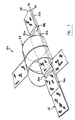
- FIG. 2 is a perspective view of the partially unwound adjustable spiral sleeve according to a preferred embodiment of the present invention.
- FIG. 3 is a perspective view of the adjustable spiral sleeve of FIG. 2 , which has been spirally wound.
- FIG. 4 is a top perspective view of the adjustable spiral sleeve regrouping a cluster of flexible lines according to a preferred embodiment of the present invention.
- FIG. 5 is a side perspective view of the adjustable spiral sleeve regrouping a cluster of flexible lines, according to a preferred embodiment of the present invention.
- FIG. 6 is a perspective view of the adjustable spiral sleeve wrapped around a cluster of lines and connected to a support, according to a preferred embodiment of the present invention.
- FIG. 7 is a perspective view of another embodiment of the adjustable spiral sleeve wrapped around a cluster of lines, wherein the support strip has two rows of offset openings.
- the adjustable spiral sleeve according to the present invention may be used in a variety of industrial applications including but not limited to the forestry, mining, transportation, automotive, robotics, chemical, electricity, plumbing and sewage industries.
- the sleeve may be used to cover, protect and/or regroup various types of hoses, tubes, cables and pipes, which are employed for a variety of purposes.
- FIGS. 2-6 shows the adjustable spiral sleeve ( 20 ) according to one embodiment of the present invention, which is used for covering at least one line.
- the adjustable sleeve ( 20 ) may be used in association with one or a plurality of lines of many sorts.
- the adjustable spiral sleeve ( 20 ) is used to cover and regroup a plurality of lines.
- lines refers to hoses, tubes, pipes, cables, wires, channels or arteries of a variety of shapes and sizes.
- the adjustable spiral sleeve ( 20 ) is used to cover and protect flexible lines such as hydraulic tubes or electric power cables, but other types of lines may also be covered, regrouped and/or protected using the adjustable sleeve ( 20 ).
- a single line may be wrapped in the adjustable sleeve ( 20 ), but preferably a plurality of lines may be regrouped into a cluster and wrapped in the adjustable sleeve ( 20 ).
- the adjustable spiral sleeve ( 20 ) includes a support strip ( 22 ) that is aligned along the length of the lines and a wrapping strip ( 24 ) that is spirally wrapped around the lines, engaging the support strip ( 22 ) and forming a plurality of loop portions ( 26 ). More regarding the wrapping strip ( 24 ) will be discussed hereinbelow.
- the support strip ( 22 ) is partly shown in dotted lines.
- the support strip ( 22 ) extends longitudinally along the line ( 12 ) or a cluster ( 14 ) of lines. By extending “longitudinally”, it should be understood that the support strip ( 22 ) is aligned with the line.
- the support strip ( 22 ) is preferably able to follow a variety of curvatures and bends that the cluster ( 14 ) of lines may take.
- the support strip ( 22 ) preferably has a straight, linear strip shape.
- the support strip may also have a variety of forms, such as a “T” or a “W” form, depending on the arrangement or intersection of the lines, as the case may be.
- a number of support strips ( 22 ) may be used for one cluster of lines.
- the support strip ( 22 ) preferably takes the form of two superimposed flat layers ( 28 , 30 ), which are attached at attachment points ( 32 ) distributed and spaced-apart at intervals along the length of the layers ( 28 , 30 ).
- the attachment points ( 32 ) preferably include stitching ( 34 ) and/or gluing.
- Other attachment means known to a person skilled in the art may also be used, such as knotting, melt-bonding, clips, buttons and bolts, depending on the material of the layers and the intended application of the sleeve.
- the attachment points include fasteners that would mitigate the wearing of the lines from frictional movement thereagainst.
- clips, bolts, and buttons when used, are preferably made of a non abrasive, non corrosive material such as plastic.
- metallic attachment means may be used.
- the longitudinal width of the stitching of each attachment point is about 1 inch. This enables a strong attachment between the superimposed layers ( 28 , 30 ). More regarding this width will be discussed hereinbelow.
- the support strip ( 22 ) has a first end ( 36 ) and a second end ( 38 ), and is provided with a plurality of connectors ( 40 ) spaced at intervals along the support strip ( 22 ) from the first end ( 36 ) to the second end ( 38 ).
- the connectors are openings ( 40 ) formed between the attachment points ( 32 ) of the two superimposed layers ( 28 , 30 ).
- each opening ( 40 ) is defined between the pair of superimposed layers ( 28 , 30 ) and between two adjacent attachment points ( 32 ).
- the openings ( 40 ) are preferably regularly spaced along the support strip ( 22 ), but may also be spaced in a variety of different distributions, as desired.
- the wrapping strip ( 24 ) is inserted through the openings successively to wrap the lines.
- the support strip ( 22 ) may include only one layer provided with holes or other shaped-openings (not shown) at intervals therealong.
- the wrapping strip ( 24 ) may pass through the holes as it spirally wraps around and along the cluster of lines.
- the holes provided in the support strip are preferably reinforced, albeit preferably with a material that does not unduly wear or damage the lines. This reinforcement may include extra stitching, a solid ring, or any other known to a skilled workman.
- the support strip ( 22 ) may take the form of a thin strip or other elongated support member, to which the wrapping strip ( 24 ) may adjustably connect to form adjustably-sized spiral loops ( 26 ).
- the appropriate connectors and type of wrapping strip should be selected depending on the type of support strip ( 22 ).
- the wrapping strip ( 24 ) is wrapped around the lines and is connectable with the connectors ( 40 ) of the support strip ( 22 ) at adjustable positions along the wrapping strip ( 24 ) to form a plurality of adjustably-sized loop portions ( 26 ) around the at least one line ( 12 ).
- Each loop portion ( 26 ) is defined between two connections to the support strip ( 22 ), preferably between two different connectors ( 4 ) which are preferably adjacent to each other, and is also defined between two adjustable positions of the wrapping strip ( 24 ).
- wrapping strip ( 24 ) it is also possible to wrap the wrapping strip ( 24 ) around the lines ( 12 ) several times while connecting the wrapping strip ( 24 ) to the same connector for each turn, so that a plurality of loop portions ( 26 ) are formed at a single connector ( 40 ). This may be desired when the wrapping strip is a thin strip that may be flexible and/or elastic, for reinforcing the sleeve at a particular place along the lines.
- the wrapping strip ( 24 ) is provided with appropriate means for being adjustably connected to the support strip ( 22 ).
- the wrapping strip ( 24 ) is simply insertable through the openings ( 40 ) of the support strip ( 22 ) to form a series of spiral loop portions ( 26 ), which are adjustably-sized.
- the wrapping strip ( 22 ) thus has the appropriate width for insertion through the openings ( 40 ).
- a first loop portion ( 26 a ) may have a smaller diameter than a second loop portion ( 26 b ).
- the diameter of the loop portions ( 26 ) may be “adjusted”, for example, by pulling on the end of the wrapping strip ( 24 ) to tighten the loop portion ( 26 ), or by pulling on the loop ( 26 ) itself to give it more slack.
- the adjustable spiral sleeve ( 20 ) may be adjusted around the cluster ( 14 ) of lines to give a tight or loose fit at specific locations along the length of the cluster ( 14 ). For example, when the cluster has a thick diameter, which is often the case at its extremities, the loop portions ( 26 ) may be adjusted to be enlarged to enable a proper fit.
- the wrapping strip ( 24 ) may be snugly wrapped around the line cluster ( 14 ). This adjustability is particularly advantageous at each end of the cluster, as at these extremities the lines often connect to the machine and the cluster tends to expand outwards.
- the wrapping strip ( 24 ) has been spirally wrapped through the openings ( 40 ) of the support strip ( 22 ) a number of times, and the loop portions ( 26 ) have been tightened around the cluster of lines.
- the support strip ( 22 ) may have another type of connector ( 40 ) with which the wrapping strip ( 24 ) can adjustably engage.
- a number of fasteners may be distributed and spaced-apart along the length of the support strip ( 22 ) and the wrapping strip ( 24 ) may have corresponding fasteners for mating with those of the support strip ( 22 ).
- Such fasteners should be secure when the wrapping strip ( 24 ) is wrapped around the lines, but should be adjustable by an operator to properly tighten the loop portions around the lines during installation.
- the support strip ( 22 ) and the wrapping strip ( 24 ) have a plurality of fasteners for mating and securing the sleeve around the lines, there should be a plurality of said fasteners distributed along the wrapping strip ( 24 ) so that it may be connected to the support strip ( 22 ) at adjustable positions along the length of the wrapping strip ( 24 ) to form the adjustably-sized loop portions ( 26 ).
- the width of the support strip ( 22 ) may be predetermined to enable desired effects.
- the support strip ( 22 ) has a width that is comparable to the diameter of the cluster of lines about which the adjustable spiral sleeve ( 20 ) is to be wrapped.
- the support strip ( 22 ) is thus able to cover one side of the cluster, while the wrapping strip ( 24 ) wrappingly covers around the circumference of the clusters.
- the support strip ( 22 ) may have a larger width to thereby radially wrap around at least part of the cluster, but it may also have a narrower width in certain circumstances.
- the wrapping strip may also have a variable width along its length.
- the wrapping strip ( 24 ) preferably includes at least one tapered end ( 41 ) to facilitate inserting it through the openings ( 40 ).
- the tapered end ( 41 ) preferably consists of a laterally inward fold of the wrapping strip ( 22 ).
- the wrapping strip ( 24 ) is adjustably wrapped around the cluster ( 14 ) of lines ( 12 ) and along the length thereof, thereby covering the cluster ( 14 ) of lines.
- each loop portion ( 26 ) of the wrapping strip ( 24 ) is defined between two adjacent connectors ( 40 ) and makes only one revolution of the cluster of lines, there is a gap ( 42 ) between each loop portion ( 26 ).
- the width of this gap ( 42 ) depends notably on the width of the attachment points ( 32 ).
- the gaps ( 42 ) may be preferred in certain applications, for instance to enable inspection of possible leaks or the arrangement of the lines and/or when simple regrouping of the cluster of lines is desired.
- the presence of a gap also minimises the amount of material necessary to cover the length of a line.
- the width of the gaps ( 42 ) may be modified. For example, a wrapping strip ( 24 ) with a greater width may be used to cover more of the lines ( 12 ).
- the gap ( 42 ) may be minimized or eliminated by looping the wrapping strip ( 24 ) more than once between adjacent openings ( 40 ).
- each loop portion ( 26 ) of the wrapping strip ( 24 ) is doubly-looped and therefore covers more area of the lines while retaining its spiral form.
- the support strip ( 22 ) is modified in order to reduce or eliminate the gap ( 42 ).
- the support strip includes three superimposed layers ( 28 , 30 , 44 ).
- the first ( 28 ) and the second ( 30 ) layers are attached to each other by a first set of longitudinally distributed spaced-apart attachment points ( 32 a ), in the same way as for the embodiment of FIGS. 2-6 .
- a third layer ( 44 ) is attached to one of the other layers at a second set of attachment points ( 32 b ), each of which is positioned in between two attachment points of the first set ( 32 a ). In this way, there are two offset rows of openings ( 40 a , 40 b ) through which the wrapping strip ( 24 ) is insertable.
- the support strip ( 22 ) is placed longitudinally alongside the line or lines and then the wrapping strip ( 24 ) is spirally wrapped around the line(s) by inserting it alternately through the openings ( 40 ) of the first and second ( 40 a , 40 b ) rows of openings.
- the gap ( 42 ) may be reduced or eliminated.
- the support strip ( 22 ) may be composed of a single layer provided with two offset rows of openings through which the wrapping strip ( 24 ) may be alternately inserted while being spirally wrapped around the lines.
- one wrapping strip ( 24 ) is used with a corresponding support strip ( 22 ).
- two or more wrapping strips ( 24 ) may be used with one support strip ( 22 ), or two or more support strips ( 22 ) may be used with one wrapping strip ( 24 ).
- a plurality of support strips ( 22 ) may be used in combination with a plurality of wrapping strips ( 24 ) to regroup and protect lines in a variety of potential arrangements, depending on the working environment or the machine to be used.
- the strips ( 22 , 24 ) preferably present sufficient strength for the desired application.
- the strength of the strips prevents breaking, tearing or elastic deformation when a significant amount of pressure or tension is applied thereto.
- the adjustable spiral sleeve ( 20 ) preferably has sufficient strength to stop or slow further movement of the machine, thereby preventing the hydraulic lines from being severely damaged.
- the adjustable spiral sleeve ( 20 ) is connected to a support ( 43 ).
- this support ( 43 ) is preferably part of the frame or substructure of the machine.
- the support strip ( 22 ) is connected to the support ( 43 ) at its two ends ( 36 , 38 ) via another strap and carabiner.
- other fasteners known in the art may be used.
- the support strip ( 22 ) and the wrapping strip ( 24 ) are removably fixed at their extremities to the frame of the machine.
- the spiral sleeve ( 20 ) is directly fixed to the machine (usually metallic parts such as a robotic arm, chassis, frame, etc.).
- FIG. 6 shows an example of how the adjustable spiral sleeve may be connected to a support.
- the support strip ( 22 ) When used in conjunction with a feller-buncher machine, for example, the support strip ( 22 ) may be connected to the hydraulic arm of the machine, thus hugging closely to the arm and holding the cluster of lines out of the way of certain dangers and snaggable objects (such as rocks, trees, etc.).
- the protective sleeve is preferably able to be attached at multiple points along the length of the cluster of hydraulic lines in order to better support the weight of the cluster, and to improve possibilities for moving the hydraulic lines.
- the wrapping strip ( 24 ), when installed in conjunction with the support strip ( 22 ), is preferably fixed to the support strip ( 22 ) at its extremities. It may be so fixed using a variety of secure fixing means, including but not limited to knots, clips, carabiners, bolts, etc.
- the openings ( 40 ) of the support strip ( 22 ) may be used to connect the support strip ( 22 ) to the superstructure of the machine via a hook ( 46 ) or another connection device, in order to guide and maintain the line cluster ( 14 ) in place.
- This may also be done using Velcro belts or collars, as well as using small chains, clips, clamps, carabiners or any other connection means known to a person skilled in the art.
- the line clusters when they are flexible may be allowed to hang freely from the machine, as the spiral sleeve ( 20 ) will protect the lines from inadvertent bumps, scrapes and wearing against a variety of objects during operation.
- the strips ( 22 , 24 ) are made of woven synthetic fibres.
- the fibres used may have a variety of microscopic forms and may be composed of a variety of polymers and/or copolymers, as would be known to a person skilled in the art.
- the synthetic fibres may be selected or engineered to give desirable characteristics to the strips of the adjustable spiral sleeve.
- the woven fabric is preferably non abrasive and presents a high strength capacity.
- the woven fabric may be composed of a base fibre material and reinforced with a variety of additional fibres to enhance certain desirable properties (such as strength, rigidity, elasticity, etc.), as the case may be.
- Polymer fibres with very low glass transition temperatures are preferable, especially for applications in cold environments.
- the fibres may also be extruded to have certain filament shapes that give rise to specific desirable properties once the fibres are woven together.
- Examples of synthetic fibres, particularly advantageous for weaving synthetic fabrics for the strips are polyamides such as nylons, polyolefins, aramides, etc. Others may include polyesters, rayons, acetates, acrylics, olefins, PLAs, Aramids or Kevlar. It is particularly preferred that the strips be made of nylon fibers woven appropriately.
- Natural fibres may also be used to produce woven fabrics appropriate for constituting the strips.
- Such fibres may be selected from plant and animal fibres known in the art.
- Cotton and hemps are examples of plant fibres. Depending on working and operating conditions, and of course material costs, a variety of different fibres and combinations thereof may be used. Examples of such materials include cotton, hemp, jute, ramie, sisal and/or kenaf.
- the material is supple, resistant and not very sensitive to temperature variation.
- the material is also preferably lightweight.
- the installation of the adjustable spiral sleeve according to the present invention may be performed according to a variety of methods.
- One such method includes the following steps:
- This above installation method is particularly preferred when employing the embodiment of the spiral sleeve ( 20 ) shown in FIGS. 2-6 .
- the wrapping strip ( 24 ) spirally around the line(s) by inserting it alternately through the openings of the first and second ( 40 a , 40 b ) rows of openings to form the loop portions ( 26 ) around the line(s).
- the wrapping strip ( 24 ) may be looped in a variety of looping patterns that would be known to a person skilled in the art.
- the spiral sleeve ( 20 ) presents a variety of advantages and features. For instance, installation of the sleeve may be performed before or after installation of the lines. The sleeve reduces the wearing of the lines from friction.
- a particular advantage of the present invention is that the tightness of the adjustable spiral sleeve ( 20 ) may be adjusted at each interval along the entire length of the line cluster, that is at each loop portion ( 26 ) of the wrapping strip ( 24 ). This enables improving the fit, covering, protection, as well as other advantages.
- the unique configuration of the support strip ( 22 ) of the spiral sleeve enables the attachment of the protective wrapping strip ( 24 ) at multiple points, thus enabling a plurality of possibilities of positioning the lines.
- the sleeve has an excellent capacity to regroup the lines into clusters regardless of the cluster dimension, so that one spiral sleeve may adapt to many conditions.
- the sleeve also preferably avoids stretching and deformation of the strips.
- the protective sleeve preferably extends to the extremities of the lines to offer a superior resistance to forces on the cluster of the lines.
- the support strip enables the regular and ordered wrapping of the wrapping strip that is protective and supple, all around the cluster of lines.
- the protective sleeve preferably for flexible hydraulic lines, also offers a variable diameter of wrapping enabling the reduction of the pressure on the ends of the cluster of lines.
- the adjustable spiral sleeve is adaptable to the diameter of the cluster.
Landscapes
- Engineering & Computer Science (AREA)
- General Engineering & Computer Science (AREA)
- Mechanical Engineering (AREA)
- Architecture (AREA)
- Civil Engineering (AREA)
- Structural Engineering (AREA)
- Clamps And Clips (AREA)
Abstract
Description
-
- Rigidity and difficulty of assemblage: The plastic material often presents properties causing it to become hard at low temperatures. For some applications at very low temperatures, the glass transition temperature of the plastic is too high to permit the sleeve to maintain the required flexibility. Assembling the single spirable band frequently presents difficulties.
- Sensitive to temperature variation: Variations in temperature may cause the sleeve to rigidify or even, at extreme temperatures, rupture.
- A low resistance to stretching: Thermoplastics may be stretched when a sufficient force is exerted on them. Stretching may lead to equipment damage, especially damage to the flexible lines covered by the plastic sleeve.
- Permanent deformation: When a thermoplastic undergoes stretching past a certain point, it becomes permanently deformed and cannot regain its previous form. This is problematic when a tight fit to the lines is desired.
- Absence of protection on the entire length of the tubes: It is difficult to wrap the plastic sleeves around the entire length of the line cluster, particularly since the extremities of a line cluster tend to expand radially. The plastic sleeves suffer from sliding and an inability to stay at the extremities of the flexible lines. Thus, the extremities of the line cluster are often exposed and left unprotected.
- Wearing of the lines due to the incomplete protection provided by the plastic sleeves: The thermoplastic band that makes up the protective sleeve may easily come unravelled or be shifted at the ends or at various points along the cluster of flexible lines, which may cause wearing of the lines. It is difficult to ensure that the sleeves do not shift, etc.
- Limited protection against the tubes catching on something and pulling apart: When the line cluster snags on a piece of equipment or another object, this plastic sleeve offers very limited resistance to protect the lines themselves from pulling apart, snapping off or being otherwise damaged.
- Needs many dimensions in order to adapt to the needs of the market: The single band that makes up the plastic spiral sleeve has limited applicability in wrapping a variety of lines and line clusters, which may present different diameters, lengths, number of lines and combinations thereof. Also, depending on the conditions (temperature, corrosion, pressure, abrasion resistance, strength, etc.) different designs of plastic sleeves may be called for.
-
- a) placing a support strip longitudinally alongside the at least one line, said support strip comprising connectors being longitudinally distributed and spaced-apart therealong; and
- b) spirally wrapping a wrapping strip around the at least one line and connecting said wrapping strip to the connectors of the support strip to form a plurality of adjustably-sized loop portions of the wrapping strips around the at least one line.
-
- c) placing a support strip longitudinally alongside the at least one line, the support strip including connectors being longitudinally distributed and spaced-apart therealong; and
- d) spirally wrapping a wrapping strip around the at least one line and connecting the wrapping strip to the connectors of the support strip to form a plurality of adjustably-sized loop portions of the wrapping strip around the at least one line.
Claims (28)
Priority Applications (1)
| Application Number | Priority Date | Filing Date | Title |
|---|---|---|---|
| US11/723,950 US7895716B2 (en) | 2006-03-22 | 2007-03-22 | Adjustable spiral sleeve for protecting lines |
Applications Claiming Priority (2)
| Application Number | Priority Date | Filing Date | Title |
|---|---|---|---|
| US78445806P | 2006-03-22 | 2006-03-22 | |
| US11/723,950 US7895716B2 (en) | 2006-03-22 | 2007-03-22 | Adjustable spiral sleeve for protecting lines |
Publications (2)
| Publication Number | Publication Date |
|---|---|
| US20070228226A1 US20070228226A1 (en) | 2007-10-04 |
| US7895716B2 true US7895716B2 (en) | 2011-03-01 |
Family
ID=38521988
Family Applications (1)
| Application Number | Title | Priority Date | Filing Date |
|---|---|---|---|
| US11/723,950 Active 2029-12-09 US7895716B2 (en) | 2006-03-22 | 2007-03-22 | Adjustable spiral sleeve for protecting lines |
Country Status (3)
| Country | Link |
|---|---|
| US (1) | US7895716B2 (en) |
| CA (1) | CA2635821C (en) |
| WO (1) | WO2007107010A1 (en) |
Cited By (12)
| Publication number | Priority date | Publication date | Assignee | Title |
|---|---|---|---|---|
| US20120241195A1 (en) * | 2011-03-25 | 2012-09-27 | Jay Thomas Doll | Cable management system and method of use |
| US20130037156A1 (en) * | 2010-04-09 | 2013-02-14 | Peter Andrew John May | Hose shroud |
| US20140182084A1 (en) * | 2012-12-27 | 2014-07-03 | Jerry R. Hill Innovations, Inc. | Adjustable Loop Load Tie-Down Strap |
| US20140261834A1 (en) * | 2013-03-15 | 2014-09-18 | Manitowoc Crane Companies, Llc | Assembly to support a conduit on a crane |
| US20150305310A1 (en) * | 2014-04-23 | 2015-10-29 | Drew A. Roberdeaux | Pet leash accessory assembly |
| US9546754B1 (en) * | 2016-06-08 | 2017-01-17 | Richard Kuhlmann | Method and device for preventing crimping in an air hose |
| US20170248254A1 (en) * | 2016-02-25 | 2017-08-31 | Nlb Corp. | Hose Shroud |
| US9774176B1 (en) * | 2013-03-15 | 2017-09-26 | The Boeing Company | Method and apparatus for protection of wiring free ends and connectors |
| US10035452B2 (en) | 2015-08-22 | 2018-07-31 | Jerry Hill Innovations, Inc. | Tie-down wrap device for securing loads and methods of use |
| US20180371787A1 (en) * | 2017-06-23 | 2018-12-27 | Chris HANNEKEN | Article, assembly and method for securing a line to an external surface, such as a fence post |
| USD868611S1 (en) | 2018-07-17 | 2019-12-03 | Walkabout Developments LLC | Hydraulic hose identification device |
| US20240301972A1 (en) * | 2023-03-07 | 2024-09-12 | Rivian Ip Holdings, Llc | Strain relief with retractor attached to cable |
Families Citing this family (7)
| Publication number | Priority date | Publication date | Assignee | Title |
|---|---|---|---|---|
| US8869841B2 (en) * | 2011-10-20 | 2014-10-28 | New Horizon Elastic Fabric Co., Ltd | Fabric straps with tubular structure containing free-floating yarns and varied width |
| US9260804B2 (en) * | 2011-10-20 | 2016-02-16 | New Horizon Elastic Fabric Co., Ltd. | Fabric straps with tubular structure containing free-floating yarns and varied width |
| USD834748S1 (en) * | 2015-12-22 | 2018-11-27 | Shih-Ling Hsu | Hair accessory |
| CN113955321B (en) * | 2021-11-12 | 2023-02-07 | 广东省魔丽显示科技有限公司 | Structure that winding displacement angle can be stably adjusted |
| JP7794030B2 (en) * | 2022-03-09 | 2026-01-06 | 住友電装株式会社 | Wire harness and method for manufacturing wire harness |
| CN117189523A (en) * | 2022-05-31 | 2023-12-08 | 金风科技股份有限公司 | Coil units, liquid cooling systems and wind turbines |
| CN115709690A (en) * | 2022-11-04 | 2023-02-24 | 张琪 | Automobile wire harness with breakage-proof appearance |
Citations (25)
| Publication number | Priority date | Publication date | Assignee | Title |
|---|---|---|---|---|
| US1466078A (en) * | 1920-06-09 | 1923-08-28 | Lillian E Washburn | Lacing device |
| US1538454A (en) * | 1924-06-12 | 1925-05-19 | Trawinski Stephan | Lacing means |
| US2684512A (en) * | 1951-03-24 | 1954-07-27 | Telecomputing Corp | Wire binder |
| US3601863A (en) | 1969-05-21 | 1971-08-31 | Milton Dorsey | Cable binder |
| US3616123A (en) | 1968-01-29 | 1971-10-26 | Johns Manville | Helicoid laminate comprising several continuous tiered strips |
| US4788089A (en) | 1985-03-06 | 1988-11-29 | Raychem Limited | Heat-recoverable article |
| US4893381A (en) | 1988-03-09 | 1990-01-16 | Frankel Eric H | Bundling strap with two adjustable closures |
| US4920235A (en) | 1987-12-04 | 1990-04-24 | Kitagawa Industries Co., Ltd. | Conductive cable sheath |
| US4929478A (en) | 1988-06-17 | 1990-05-29 | The Bentley-Harris Manufacturing Company | Protective fabric sleeves |
| US5075934A (en) | 1990-05-17 | 1991-12-31 | Osedo Stuart S | Fastening device |
| US5111554A (en) * | 1989-08-07 | 1992-05-12 | Sweers Ronald L | Hold-down strap for a tarp |
| CA2135380A1 (en) | 1993-05-18 | 1994-11-24 | Roger B. Anthony | Double armor cable with auxiliary line |
| US5524327A (en) | 1994-11-14 | 1996-06-11 | Mednext, Inc. | Malleable clip |
| US5632071A (en) * | 1995-06-01 | 1997-05-27 | Maunder; Martha | Flexible hinge connector |
| US6051291A (en) | 1997-07-18 | 2000-04-18 | Federal-Mogul Systems Protection Group, Inc. | Heat reflective sleeve with insulating air pocket |
| US6309721B1 (en) | 1997-01-06 | 2001-10-30 | Federal-Mogul Systems Protection Group, Inc. | Flexible protective sleeve |
| US20020098311A1 (en) | 1999-09-02 | 2002-07-25 | Michael Lindner | Protective sheathing |
| US20020190451A1 (en) | 2001-06-01 | 2002-12-19 | The University Of Akron | Fiber-reinforced composite springs |
| US20030079790A1 (en) | 1999-12-10 | 2003-05-01 | Atkinson Alan William | Flexible protective sleeve |
| US20030097735A1 (en) | 2000-05-03 | 2003-05-29 | Shore Jeffrey Pascal | Fitting for the use as a means for the gripping of one or more objects |
| US6635825B2 (en) | 2000-02-29 | 2003-10-21 | Sumitomo Wiring Systems, Ltd. | Structure for wiring a wire harness between an automobile body and a mobile article, and a method of protecting an electric wire group of a wire harness |
| US20040040125A1 (en) | 2001-03-07 | 2004-03-04 | Schultz Joseph P. | Loopable, secure multiple-fastening-strap systems |
| US6842948B2 (en) | 2001-08-30 | 2005-01-18 | Alliance Rubber Company | Rubber band retainer apparatus |
| US6878873B2 (en) | 2001-08-09 | 2005-04-12 | Federal-Mogul World Wide, Inc. | Damping sleeve with resilient support members |
| US7185399B2 (en) | 2003-08-06 | 2007-03-06 | Medcount Systems, C.L.C. | Method and apparatus for securing cables and the like |
-
2007
- 2007-03-22 WO PCT/CA2007/000474 patent/WO2007107010A1/en not_active Ceased
- 2007-03-22 CA CA2635821A patent/CA2635821C/en active Active
- 2007-03-22 US US11/723,950 patent/US7895716B2/en active Active
Patent Citations (27)
| Publication number | Priority date | Publication date | Assignee | Title |
|---|---|---|---|---|
| US1466078A (en) * | 1920-06-09 | 1923-08-28 | Lillian E Washburn | Lacing device |
| US1538454A (en) * | 1924-06-12 | 1925-05-19 | Trawinski Stephan | Lacing means |
| US2684512A (en) * | 1951-03-24 | 1954-07-27 | Telecomputing Corp | Wire binder |
| US3616123A (en) | 1968-01-29 | 1971-10-26 | Johns Manville | Helicoid laminate comprising several continuous tiered strips |
| US3601863A (en) | 1969-05-21 | 1971-08-31 | Milton Dorsey | Cable binder |
| US4788089A (en) | 1985-03-06 | 1988-11-29 | Raychem Limited | Heat-recoverable article |
| US4920235A (en) | 1987-12-04 | 1990-04-24 | Kitagawa Industries Co., Ltd. | Conductive cable sheath |
| US4893381A (en) | 1988-03-09 | 1990-01-16 | Frankel Eric H | Bundling strap with two adjustable closures |
| US4929478A (en) | 1988-06-17 | 1990-05-29 | The Bentley-Harris Manufacturing Company | Protective fabric sleeves |
| US5111554A (en) * | 1989-08-07 | 1992-05-12 | Sweers Ronald L | Hold-down strap for a tarp |
| US5075934A (en) | 1990-05-17 | 1991-12-31 | Osedo Stuart S | Fastening device |
| US5384430A (en) | 1993-05-18 | 1995-01-24 | Baker Hughes Incorporated | Double armor cable with auxiliary line |
| CA2135380A1 (en) | 1993-05-18 | 1994-11-24 | Roger B. Anthony | Double armor cable with auxiliary line |
| US5528824A (en) | 1993-05-18 | 1996-06-25 | Baker Hughes Incorporated | Method of forming a double armor cable with auxiliary line for an electrical submersible pump |
| US5524327A (en) | 1994-11-14 | 1996-06-11 | Mednext, Inc. | Malleable clip |
| US5632071A (en) * | 1995-06-01 | 1997-05-27 | Maunder; Martha | Flexible hinge connector |
| US6309721B1 (en) | 1997-01-06 | 2001-10-30 | Federal-Mogul Systems Protection Group, Inc. | Flexible protective sleeve |
| US6051291A (en) | 1997-07-18 | 2000-04-18 | Federal-Mogul Systems Protection Group, Inc. | Heat reflective sleeve with insulating air pocket |
| US20020098311A1 (en) | 1999-09-02 | 2002-07-25 | Michael Lindner | Protective sheathing |
| US20030079790A1 (en) | 1999-12-10 | 2003-05-01 | Atkinson Alan William | Flexible protective sleeve |
| US6635825B2 (en) | 2000-02-29 | 2003-10-21 | Sumitomo Wiring Systems, Ltd. | Structure for wiring a wire harness between an automobile body and a mobile article, and a method of protecting an electric wire group of a wire harness |
| US20030097735A1 (en) | 2000-05-03 | 2003-05-29 | Shore Jeffrey Pascal | Fitting for the use as a means for the gripping of one or more objects |
| US20040040125A1 (en) | 2001-03-07 | 2004-03-04 | Schultz Joseph P. | Loopable, secure multiple-fastening-strap systems |
| US20020190451A1 (en) | 2001-06-01 | 2002-12-19 | The University Of Akron | Fiber-reinforced composite springs |
| US6878873B2 (en) | 2001-08-09 | 2005-04-12 | Federal-Mogul World Wide, Inc. | Damping sleeve with resilient support members |
| US6842948B2 (en) | 2001-08-30 | 2005-01-18 | Alliance Rubber Company | Rubber band retainer apparatus |
| US7185399B2 (en) | 2003-08-06 | 2007-03-06 | Medcount Systems, C.L.C. | Method and apparatus for securing cables and the like |
Cited By (20)
| Publication number | Priority date | Publication date | Assignee | Title |
|---|---|---|---|---|
| US20130037156A1 (en) * | 2010-04-09 | 2013-02-14 | Peter Andrew John May | Hose shroud |
| US9052042B2 (en) * | 2010-04-09 | 2015-06-09 | Peter Andrew John May | Hose shroud |
| US8399769B2 (en) * | 2011-03-25 | 2013-03-19 | Jay Thomas Doll | Cable management system and method of use |
| US20120241195A1 (en) * | 2011-03-25 | 2012-09-27 | Jay Thomas Doll | Cable management system and method of use |
| US9339086B2 (en) * | 2012-12-27 | 2016-05-17 | Jerry R. Hill Innovations, Inc. | Adjustable loop load tie-down strap |
| US20140182084A1 (en) * | 2012-12-27 | 2014-07-03 | Jerry R. Hill Innovations, Inc. | Adjustable Loop Load Tie-Down Strap |
| US9774176B1 (en) * | 2013-03-15 | 2017-09-26 | The Boeing Company | Method and apparatus for protection of wiring free ends and connectors |
| US20140261834A1 (en) * | 2013-03-15 | 2014-09-18 | Manitowoc Crane Companies, Llc | Assembly to support a conduit on a crane |
| US20150305310A1 (en) * | 2014-04-23 | 2015-10-29 | Drew A. Roberdeaux | Pet leash accessory assembly |
| US9936679B2 (en) * | 2014-04-23 | 2018-04-10 | Drew A. Roberdeaux | Pet leash accessory assembly |
| US10035452B2 (en) | 2015-08-22 | 2018-07-31 | Jerry Hill Innovations, Inc. | Tie-down wrap device for securing loads and methods of use |
| US20170248254A1 (en) * | 2016-02-25 | 2017-08-31 | Nlb Corp. | Hose Shroud |
| US9964237B2 (en) * | 2016-02-25 | 2018-05-08 | Nlb Corp. | Hose shroud |
| US9546754B1 (en) * | 2016-06-08 | 2017-01-17 | Richard Kuhlmann | Method and device for preventing crimping in an air hose |
| US20180371787A1 (en) * | 2017-06-23 | 2018-12-27 | Chris HANNEKEN | Article, assembly and method for securing a line to an external surface, such as a fence post |
| US11525278B2 (en) * | 2017-06-23 | 2022-12-13 | Chris HANNEKEN | Article, assembly and method for securing a line to an external surface, such as a fence post |
| US11773617B2 (en) | 2017-06-23 | 2023-10-03 | Chris HANNEKEN | Article and assembly for securing a line to an external surface, such as a fence post |
| US12188252B2 (en) | 2017-06-23 | 2025-01-07 | Chris HANNEKEN | Method for securing a line to an external surface, such as a fence post |
| USD868611S1 (en) | 2018-07-17 | 2019-12-03 | Walkabout Developments LLC | Hydraulic hose identification device |
| US20240301972A1 (en) * | 2023-03-07 | 2024-09-12 | Rivian Ip Holdings, Llc | Strain relief with retractor attached to cable |
Also Published As
| Publication number | Publication date |
|---|---|
| US20070228226A1 (en) | 2007-10-04 |
| CA2635821A1 (en) | 2007-09-27 |
| CA2635821C (en) | 2014-06-10 |
| WO2007107010A1 (en) | 2007-09-27 |
Similar Documents
| Publication | Publication Date | Title |
|---|---|---|
| CA2635821C (en) | Adjustable spiral sleeve for protecting lines | |
| US8127405B2 (en) | Reusable hose bundling sleeve | |
| US10711921B2 (en) | Reusable hose bundling sleeve | |
| KR960000086B1 (en) | Abrasion Resistant Braided Sleeve | |
| JP4298514B2 (en) | Protective cover | |
| US8367182B2 (en) | Wrappable textile sleeve with integral attachment and closure device | |
| US10590574B2 (en) | Abrasion resistant braided textile sleeve and method of construction thereof | |
| EP2971307B1 (en) | Warp knit wrappable sleeve with extendable electro-functional yarns and method of construction thereof | |
| KR101099432B1 (en) | Multi-branch junction overwrap | |
| US20020117321A1 (en) | Rigidized protective sleeving | |
| US20080254244A1 (en) | Textile sleeve for protecting elongate members and method of construction | |
| KR940703638A (en) | Wraparound Sleeve with Lock | |
| CN1468785A (en) | Straps for harness branches | |
| CN114026760B (en) | Fastening component | |
| US6227094B1 (en) | Braided tubular article | |
| US5441790A (en) | Rope abrasion protection device | |
| US20040255435A1 (en) | Reusable hose bundling sleeve | |
| EP2778108B1 (en) | Assembly to couple a conduit to a crane | |
| US20090293236A1 (en) | Hook and Loop Tie with a Non-Slip Area | |
| US7219397B2 (en) | Elastic foreshortening of cable or other linear structures | |
| WO2000017085A9 (en) | Lifting sling system having multiple strap components | |
| CN222543339U (en) | Hose protective cover for construction machinery and construction machinery | |
| WO2010010170A1 (en) | Protective sheath for piping | |
| EP2873897A2 (en) | Concrete element for protecting one or several cables and/or pipelines in an underwater installation |
Legal Events
| Date | Code | Title | Description |
|---|---|---|---|
| AS | Assignment |
Owner name: TAIMI R&D INC., CANADA Free format text: ASSIGNMENT OF ASSIGNORS INTEREST;ASSIGNORS:TAILLON, MICHEL;LAWSON, JEREMY;REEL/FRAME:019439/0040 Effective date: 20070518 |
|
| STCF | Information on status: patent grant |
Free format text: PATENTED CASE |
|
| FPAY | Fee payment |
Year of fee payment: 4 |
|
| MAFP | Maintenance fee payment |
Free format text: PAYMENT OF MAINTENANCE FEE, 8TH YR, SMALL ENTITY (ORIGINAL EVENT CODE: M2552); ENTITY STATUS OF PATENT OWNER: SMALL ENTITY Year of fee payment: 8 |
|
| MAFP | Maintenance fee payment |
Free format text: PAYMENT OF MAINTENANCE FEE, 12TH YR, SMALL ENTITY (ORIGINAL EVENT CODE: M2553); ENTITY STATUS OF PATENT OWNER: SMALL ENTITY Year of fee payment: 12 |
|
| FEPP | Fee payment procedure |
Free format text: ENTITY STATUS SET TO UNDISCOUNTED (ORIGINAL EVENT CODE: BIG.); ENTITY STATUS OF PATENT OWNER: LARGE ENTITY |
|
| AS | Assignment |
Owner name: FASTER HYDRAULICS CANADA CORPORATION, CANADA Free format text: ASSIGNMENT OF ASSIGNORS INTEREST;ASSIGNOR:TAIMI R&D INC.;REEL/FRAME:075367/0972 Effective date: 20260610 |